Modeling and Dynamics Characteristics Analysis
of a Linear Oscillating Motor
Huisheng Liang
DFH Satellite Co. Ltd, Beijing, China Email: [email protected]
Abstract—This paper investigates a novel linear oscillating motor for the application of linearly driven hydraulic pump. The motor working principle and special structure was elaborated. Its time-domain, frequency-domain and vector dynamics model are established respectively. And based on the model, the motor resonant frequency characteristic is analyzed. In addition, the influence of dynamic parameters on the resonant frequency characteristic is invested. A resonant capacitor is connected to the coils to compensate the winding inductance, and the motor power factor and mechanical characteristics is researched. At last, the motor power spectrum is acquired to contribute to the dynamics parameters design and optimization.
Index Terms—linear oscillating motor, dynamics model, resonant frequency, power factor
I. INTRODUCTION
Linear Oscillating Motors (LOM) could provide short-stroke reciprocate motion with high efficiency, and are being employed increasingly in many applications, such as vibrators, fluid pump, artificial heart devices, hybrid electric vehicle, and compressors, etc. Particular examples include stirling cycle cryogenic coolers for satellite remote sensing systems and linear compressor for refrigerant and air conditioning [1]. In these industry applications, instead of traditional rotary motor operating mode, the linear oscillating motor provides thrust force directly to pay load without rotary-to-linear counterparts such as screws, gears, and crank, so the absence of these mechanical counterparts brings in many significant advantages including simplicity, efficiency, dynamic performance, reliability and lifespan, etc.
The operation mode of LOM is to drive the actuator at a mechanical resonant frequency in order to make the linear actuator not only realize small size and power input, but also achieve optimum efficiency and velocity.
Generally, the researches of linear oscillating motor can be divided into three types [2]: iron, moving-coil and moving magnet motors. The moving-iron motor conforms to the principle of magnetic reluctance. The coils are stator, while slotted iron tube is the mover. When the coils are energized, the mover is actuated under the attractive force of reluctance. The moving iron type can produce high thrust. But its large inertia may cause low dynamic performance. Moving-coil motor is based
Manuscript received April 26, 2017; revised June 30, 2017.
on the principle of Lorentz force [3]. The moving coil type has small mover mass and high dynamics, but at meanwhile, its thrust is relative smaller due to its large equivalent air gap.
So, in order to either achieve large force output or the relative higher resonant frequency, the moving magnet motor has received more interests recently, due to their inherent high power density and high efficiency [4].
The purpose of this paper is to develop a tubular permanent-magnet linear oscillating motor with large thrust and high dynamic performance for the application of a kind of linearly driven hydraulic pump. This paper is organized as follows. Section II presents the design concept and structure of LOM. In Section III, dynamics model for LOM is set up by the time-domain, frequency-domain and vector analysis. Section IV invests the influence of dynamic parameters on the resonant frequency characteristics. Finally, conclusion is made in Section V.
II. CONCEPT DESIGN AND OPERATING PRINCIPLE
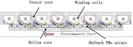
The operating principle of linear oscillating motor is illustrated in Fig. 1. Magnetic flux flows through stator core, air-gap, PM and mover core in turns, and forms a closed loop. Energizing windings on the stator produce N and S poles at corresponding stator teeth. The interaction between magnetic field of stator and mover generates the electromagnetic force and moves the mover in the axial direction. By varying the current input in the coils periodically, reciprocating motions are achieved with controllable frequency and amplitude. Multiple permanent magnet (PM) poles and electromagnetic (EM) poles are employed to reduce flux leakage and generate high thrust output.
Figure 1. Magnetic circuit working principle.
employ springs to balance the mover’s inertia force. Thus, the motor can be seen as a mass-spring resonant system. When the motor works, it needs to generate the sinusoidal displacement output at the mechanical resonance frequency to improve the system efficiency.
Based on the above working principle, a novel LOM is designed and its schematic structure is illustrated in Fig. 2. The stator is made of mild steel to increase flux density in the air-gap. Coils are wound on eight stator slots. The mover is a hollow iron cylinder composed of quasi-Halbach PM arrays. The flux density in the air-gap can be enhanced to increase the thrust, whereas it is weakened on the other side due to the self-shielding effect of quasi- Halbach arrays. The self-shielding effect also allows the design of hollow structure for installation of springs and bearings, this not only reduces the mover mass to improve the motor dynamics, but also achieves more compact size and improve the power density.
Figure 2. Schematic structure of the LOM (Sectional view).
III. DYNAMIC MODELLING AND SIMULATION
A. Time Domain Modeling
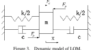
The LOM could be seen as a single DOF mass-spring-damping resonant system [5], as shown in Fig. 3.
Figure 3. Dynamic model of LOM.
And, so the dynamic equation of LOM is expressed as:
2 2 e p
dx d x
F F kx c m
dt dt
(1)
where Fe are the electromagnetic force, and Fp,k,c,
andm is the external load, spring stiffness, damping coefficient, and mover mass, respectively.
At meantime, the voltage equation of LOM is given by:
E di
u iR L K v
dt
(2)
where KE is the back-EMF coefficient. The dynamic model block is deduced and shown in Fig. 4.
1/ 1 L
R s
ke
1 m
1 s
1 s
k
c
E k p F
U(s)
I(s)
F(s)
E(s)
V(s) X(s)
Figure 4. Dynamic model block for LOM.
Based the time domain modeling, the relation between consumed current and excited frequency could be acquired, which is shown as in Fig. 5.
0 0.05 0.1 0.15 0.2 0.25 0.3 0.35 0.4
-2 0 2 4 6 8 10 12 14 16
Time(s)
C
u
r
r
e
n
t
(
A
)
Figure 5. Time-domain characteristics of LOM current at resonant state.
While the LOM works on the resonance frequency with no external load, the consumed current comes to almost zero as the motor motion becomes steady. It reveals that the motor could achieve the best efficiency while it works at completely resonant state.
B. Frequency Domain Analysis
Base on the dynamic equations, the LOM frequency modelling can be obtained, and the transfer function between the motor velocity and electromagnetic force is expressed as [6]:
2 ( ) ( )
( ) V
e
V s s
G s
F s ms cs k
(3)
The frequency domain analysis is shown in Fig. 6. It shows that on resonant frequency, the motor achieves the maximum speed under the condition of motor rated thrust. This reveals the reason of creating mechanical resonance by introducing springs for LOM, and also verifies the resonant frequency is the LOM optimal working point.
Frequency (Hz)
P
h
a
s
e
(
d
e
g
)
V
e
l
o
c
i
t
y
(
d
B
)
C. Vector Analysis
The dynamic model of LOM could also be transformed into vector expressions, as are shown [7]:
( ) e
k
jmw j c V F
w
(4)
(RjwL I K V) e U (5)
e e
F K I (6)
The above vector parameter relationship can be expressed as in Fig. 7.
U
V
()
eIF
X
p
F
1
2
i
v
Figure 7. Dynamic vector parameter relationship of LOM.
So, the velocity of mover can be expressed as:
e
K I V
k
c jmw j
w
(7)
From the above equations, the following relations could be obtained:
2 2
2 2 2 2
( )
( ( ) )( )
e m m
e m K I V
k
c mw w
K U
k
c mw a b
w
(8)
arctan( )
v i
k
mw w
c
(9)
here,
v ,
i are the phase angle of the velocity andcurrent, respectively,the current amplitude is as shown:
2 2 m m
U I
a b
(10)
2 2
( )
e E
K K c
a R
k
c mw
w
(11)
2 2
( )
( )
E e
k K K mw
w
b wL
k
c mw
w
(12)
By the above equations, it could be concluded that the motor velocity could be the maximum, and the excited current is the minimum simultaneously, when the motor thrust excitation frequency meets the conditionmw k w 0. This is coincided with the above analysis and simulation from the time domain and frequency domain analysis.
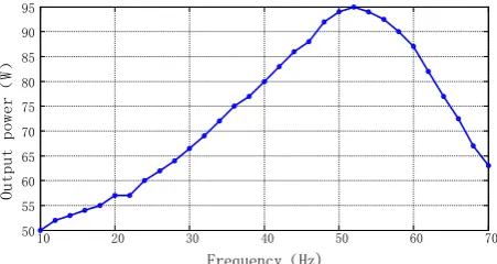
In addition, the output power of LOM can be deduced as following:
2 1
2 2
cos
2 2( ( ) )
f em em m
out
e f
c F F V
P
k
c mw w
(13)
So, once the amplitude of the motor rated thrust is fixed, and simultaneously, when the motor works on the resonant frequency, its output power is the maximum. The simulation result is in Fig. 8.
10 20 30 40 50 60 70 50
55 60 65 70 75 80 85 90 95
Frequency(Hz)
O
u
t
p
u
t
p
o
w
e
r
(
W
)
Figure 8. Relationship between output power and excited frequency.
And the motor input power is as follow:
cos 2
m m
in i
U I
P (14)
So, the efficiency can be expressed as:
( ) e
k
jmw j c V F
w
(15)
2
2 2 2
( ( ) )
f e out
e in
f f e
c K P
k
P R c mw c K
w
(16)
This expression indicates clearly that the motor efficiency is highest when it works on the resonant frequency [8], as shown in Fig. 9.
0 20 40 60 80 100 120 140 160 180 200 0
0.2 0.4 0.6 0.8 1
Frenquency(Hz)
E
f
f
i
c
i
e
n
c
y
IV. PARAMETER ANALYSIS
A. Resonant Capacitor
The LOM installs the springs to improve the mechanical power factor to utilize the motor thrust ability. Similarly, it can improve the electrical power factor to make the resonant capacitor in series of the electrical system [9].
The comparison of electrical power factor with and without resonant capacitor is shown Fig. 10. It reveals that the motor electrical power factor could achieve the maximum value “1” while the motor works at the resonant frequency with the resonant capacitor.
10 20 30 40 50 60 70 80 90 100 0
0.2 0.4 0.6 0.8 1
Frenquency(Hz)
P
o
w
e
r
f
a
c
t
o
r
With capacitor
Without capacitor
Figure 10. Comparison of power factor with and without resonant capacitor.
In addition, it can also improve the motor mechanical characteristics to make the motor coils in series of resonant capacitor. This can be explained in the following Fig. 11.
0 100 200 300 400 500 600 700 0.5
0.6 0.7 0.8 0.9 1 1.1 1.2 1.3
Damping coefficient(N/(m/s))
A
v
e
r
a
g
e
s
p
e
e
d
(
m
/
s
)
With capacitor
Without capacitor
Figure 11. Comparison of mechanical characteristics with and without resonant capacitor.
From the comparison, the motor mechanical characteristics and mover speed steady with resonant capacitor is better compared with the one without resonant capacitor.
B. Resonant Frequency and Efficiency
Because of the limited stroke and thrust, the LOM needs to have relative high resonant frequency, thus the motor mover has bigger motion velocity [10]. Moreover, the relative high resonant frequency can also make the motor have higher efficiency. The relationship between resonant frequency and efficiency is show as Fig. 12.
It reveals that the LOM has higher efficiency when the designed resonant frequency is higher. So, this rule can
guide us how to design the LOM to improve the motor efficiency.
10 20 30 40 50 50
60 70 80 90
Resonant frequency (Hz)
E
f
f
i
c
i
e
n
c
y
(
%
)
Figure 12. Relationship between resonant frequency and efficiency.
C. Coils Current and Average Speed
The relationship between the motor coils current and average speed under different exited frequency could reveal the characteristics of the motor power output. The LOM works on different frequency with no load, and the relationship between the coils current and average speed is show in Fig. 13.
When the motor works on the different excited frequency except for the resonant frequency 18.5Hz, the LOM could be seen as a generator for half a cycle and an electric motor for the other half, so the whole output power of LOM is zero under this operating mode with no load.
-30 -20 -10 0 10 20 30
-3 -2 -1 0 1 2 3
6Hz 10Hz 18.5Hz 24Hz 30Hz
Current(A)
A
v
e
r
a
g
e
s
p
e
e
d
(
m
/
s
)
Figure 13. LOM power spectrum with no load.
-15 -10 -5 0 5 10 15
-1 -0.5
0 0.5 1
6Hz 14Hz 18.5Hz
22Hz 26Hz
Current(A)
A
v
e
r
a
g
e
s
p
e
e
d
(
m
/
s
)
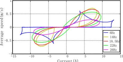
Figure 14. LOM power spectrum with load.
that the designed motor has relative smaller spring stiffness compared to the load, and does not give the optimal power output.
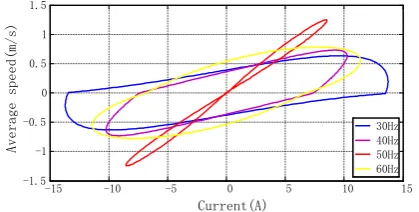
In order to improve the motor power output, the spring stiffness needs to be designed to match the external load, thus the motor works only in the first and third quadrant on resonant frequency. Here, the motor resonant frequency is improved to 50Hz from 18.5Hz, and the relationship between the coils current and average speed is show in Fig. 15.
-15 -10 -5 0 5 10 15
-1.5 -1 -0.5 0 0.5 1 1.5
30Hz 40Hz 50Hz 60Hz
Current(A)
A
v
e
r
a
g
e
s
p
e
e
d
(
m
/
s
)
Figure 15. LOM power spectrum with increased resonant frequency.
From the above comparison, it is concluded that the motor has better thrust ability and higher efficiency simultaneously, when the designed spring stiffness and resonant frequency is increased.
V. CONCLUSION
This paper proposes a novel tubular linear oscillating motor. A hollow structure is proposed for the mover design based on the self-shielding effect of quasi-Halbach PM arrays, which can reduce the mover mass to improve the motor dynamics. And then, the time-domain and frequency-domain dynamic model of LOM are established respectively. According to this model, the resonant frequency characteristic of LOM is acquired, and by the analysis on the power output and efficiency, it is concluded that the LOM mechanical resonant frequency is the optimal working point. In addition, the influence of LOM dynamic parameters on the resonant frequency characteristic is invested. A resonant capacitor is connected to the coils to compensate the winding inductance, and the motor power factor and mechanical
characteristics is researched. Finally, the relationship between the motor power output & efficiency and resonant frequency is conducted, and this could provide guidance to LOM dynamic parameter design.
REFERENCES
[1] J. B. Wang, D. Howe, and Z. Y. Lin, “Design optimization of short-stroke single-phase tubular permanent magnet motor for refrigeration applications,” IEEE Trans. on Industrial Electronics, vol. 57, pp. 327-334, January 2010.
[2] M. A. Rahman and P. Zhou, “Analysis of brushless permanent magnet synchronous motors,” IEEE Trans on Industrial Electronics, vol. 43, pp. 256-267, Jan. 1996.
[3] S. M. Jang and S. S. Jeong, “Armature reaction effect and inductance of moving coil linear oscillatory actuator with unbalanced magnetic circuit,” IEEE Trans. Magnetics, vol. 37, no. 4, pp. 2847-2850, Feb. 2001.
[4] S. M. Jang, et al., “Thrust analysis and measurements of tubular linear actuator with cylindrical Halbach array,” IEEE Trans.
Magnetics,vol. 41, no. 5, pp. 2028-2031, 2005.
[5] N. Chen, et al., “Study on static and dynamic characteristics of moving magnet linear compressors,” Cryogenics,vol. 47, no. 9, pp. 457-467, 2007.
[6] T. W. Chun, et al., “A novel strategy of efficiency control for a linear compressor system driven by a PWM inverter,” IEEE Trans. Industrial Electronics,vol. 55, no. 1, pp. 296-301, 2008.
[7] L. N. Tutelea, et al., “Linear permanent magnet oscillatory machine: Comprehensive modeling for transients with validation by experiments,” IEEE Trans. Industrial Electronics,vol. 55, no. 2, pp. 492-500, 2008.
[8] J. Wang, Z. Lin, and D. Howe, “Analysis of a short-stroke, single-phase, quasi-Halbach magnetised tubular permanent magnet motor for linear compressor applications,” Electric Power Applications, vol. 2, no. 3, pp. 193-200, 2008.
[9] N. C. Tsai and C. W. Chiang, “Innovative electromagnetic actuator applied for high-frequency reciprocal translation,”
Electromagnetics,vol. 31, no. 1, pp. 45-62, 2011.
[10] L. Tutelea, et al., “A set of experiments to more fully characterize linear PM oscillatory machines,” IEEE Trans. Magnetics,vol. 41, no. 10, pp. 4009-4011, 2005.