19
DESIGN AND IMPLEMENTATION OF SMS BASED WIRELESS
APPLIANCE CONTROL SYSTEM
T. A. ABDUL-HAMEED & D.A. FOLARIN
Department of Electrical & Electronics Engineering Federal Polytechnic, Ede.
ABSTRACT
Using GSM network, a control system that acts as an embedded system which can monitor and control electrical appliances and devices locally using built-in input and output peripheral is designed and implemented. Remotely the system allows the user to effectively monitor and control the house/office appliances and equipments via the mobile phone set by sending commands in the form of SMS messages
.
Keywords: Short Message Service (SMS), Global System for Mobile communication (GSM), AT Commands, and Automation.
INTRODUCTION
Remote management of several home and office appliances is a subject of growing interest (Potamitis et al. 2005). These days, apart from supporting voice calls a mobile phone can be used to send text messages as well as multimedia messages (that may contain pictures, graphics, animations, etc). Instant messaging allows quick transmission of short messages that allow an individual to share ideas, opinions and other relevant information (Delgado et al., 2006). This concept is used in this work to design a platform that receive messages in form of commands which are converted to electrical signals that commands the energy level (ON & OFF) at which the electrical appliances and devices connected to the platform will be.
The number of GSM subscribers is likely to be increasing exponentially every year (Hillebrand, 2001). One of the major services offered by GSM operators is Short Message Service (SMS). A Short Message Service (SMS) is employed in the activation of a switch in this work. The sent message is received and processed further as may be required to perform several operations. The type of the operation to be performed depends on the nature of the SMS sent. First, the sent SMS is stored in the mobile station, decoded by the micro-controller and then the required control signal is generated and sent to the intermediate hardware that has been designed according to the command received in form of the sent message. A particular mobile SAGEM set (MyX5-2) was selected for the implementation.
A BRIEF SURVEY OF EXISTING LITERATURE
Potamitis et al. (2003) suggested the use of speech to interact remotely with the home appliances to perform a particular action on behalf of the user. The approach is inclined for people with disability to perform real-life operations at home by directing appliances through speech. Voice separation strategy is selected to take appropriate decision by speech recognition. Conte and
Scaradozzi (2003) view home automation systems as multiple agent systems (MAS). Home automation for home management to improve performance was the major task.
Alkar and Buhur (2005) proposed an Internet Based Wireless Home Automation System for Multifunctional Devices. Their work proposed a low cost and flexible web-based solution. The system has some limitations such as the range and power failure.
Delgado et al. (2006) devised several network technologies in the implementation of home automation systems. Lack of robustness, compatibility issue and acceptability among several categories of people were extensively dealt with.
Ciubotaru-Petrescu et al. (2006) presented a design and implementation of SMS based control for monitoring systems. The paper has three modules involving sensing unit for monitoring the complex applications. A processing unit that is microcontroller and a communication module that uses GPRS modem or cell phone via serial port RS-232. The SMS is used for status
reporting such as power failure
.
20
Primary health-care management for the rural population was the focus of Murthy (2008). The use of the mobile web-technologies for providing the PHC services to the rural population was proposed. The system involves the use of SMS and cell phone technology for information management, transactional exchange and personal communication.Jawarkar et al. (2008) worked along speech/spoken commands as the basis of remote monitoring through the conversion of speech into a text SMS on a mobile phone. Khiyal et al. (2009) focused mainly on the controlling of home appliances remotely and providing security when the user is away from the place. The system is SMS based and uses wireless technology to revolutionize the standards of living. This system provides ideal solution to the problems faced by home owners in daily life. The system is adaptable and cost-effective. The system uses
GSM technology thus providing ubiquitous access to the system for security and automated appliance control.
METHODOLOGY
The SMS remote controller uses a GSM phone which serves as a transceiver that establishes a network connection between the user mobile phone and the micro-controller. The micro-controller upon receiving an instruction from the phone searches its memory to ascertain if such function exists. The relays connected to the output terminals of the micro-controller serves as electro-mechanical switches whose status (ON and OFF) is determined by the instruction from the micro-controller. The inputs to the micro-controller serve as switches through which status (open or closed) of doors and windows can be monitored.
Block Diagram and Circuit Realization
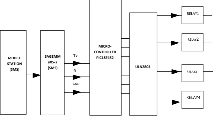
The block diagram for the system is as in figure 1.
Figure 1: Block diagram of the Switching Control System.
The first Mobile station is used as a transmitting section from which the subscriber sends text messages that contain commands and instructions to the second mobile station which is located in a specific area where our control system is also located. The 2nd mobile phone as indicated in the block diagram is a Sagem MyX5-2 mobile set. The received SMS message is stored in the SIM memory of the phone and then extracted by the microcontroller and processed accordingly to carry out specific operations. The relay driver (BUFFER ULN2003) is used to drive the relay circuits which switches the different appliances connected to the interface.
The circuit in figure 2 illustrates the supply of the voltage required by the GSM phone (3.9v). The LM317 is an adjustable voltage regulator which requires two external resistors, 10K and 1K to produce the needed voltage. A variable resistor can be used to vary the Vout
if the design demands.
The circuit in figure 3 solves the problem of switching ON the GSM phone module any time the circuit is powered since there is no battery attached to the phone. The circuit consists of a 555 timer connected with a 10k and 100uF capacitor which gives a time delay of 1.0sec (T=RC). When the circuit is powered, the NE555
Tx
R
x
GND MOBILE
STATION (SMS)
SAGEMM yX5-2
(SMS) ULN2803
MICRO-CONTROLLER
PIC18F452
RELAY1
RELAY2
RELAY3
21
produces a 1.0sec delay and then allow the negative voltage to trigger the phone.The relay driver is used to isolate both the controlling and the controlled device. The relay is an electromagnetic device, which consists of solenoid, moving contacts (switch) and restoring spring and consumes comparatively large amount of power. This makes it possible for the interface IC to drive the relay satisfactorily. To enable this, a driver circuitry, which acts as a buffer circuit, is incorporated between them. The driver circuitry senses the presence of a “high” level at the input and drives the relay from another voltage source. Hence the relay is used to switch the electrical supply to the appliances. The circuit consists of four relays (12V, 10A) each with power rating of 1000 Watts (1KW). The circuit can be connected to a 4000 watts (4KW) worth of load.
Whenever the rated voltage is connected across the coil, the backward electromotive force (emf) opposes the current flow. After a short period the supplied voltage overcome the back emf and current flow through the coil increases. When the current is equal to the activating current of relay, the core is magnetized and it attracts the moving contacts. Now the moving contact leaves from its initial position denoted “(NC)” normally closed terminal which is a fixed terminal. The common contact or moving contact establishes the GSM Based Control System connection with a new terminal which is indicated as a normally open terminal “(NO)”.
Whenever, the supply coil is withdrawn the magnetizing force is vanished. Now, the spring pulls the moving contact back to initial position, where it makes a connection with NC terminal.
The external clock circuit is illustrated in figure 4. This is an electronic circuit that uses the mechanical resonance of a vibrating crystal of piezoelectric material to create an electrical signal with a frequency of 20MHz. This frequency is used for keeping track of time, in order to provide a stable clock signal for the microcontroller. The overall speed of the microcontroller operation is entirely dependent on the clock frequency. The higher the speed of the crystal oscillator, the faster is the processing of data by the PIC microcontroller.
The control circuit between the GSM phone and the micro-controller is shown in figure 5.The GSM phone is connected in series with the micro-controller. The transmitting pin of the phone (Tx) is connected to the receiving pin (Rx) of the micro-controller and vice versa. The transmitting pin of the micro-controller is connected through an amplifying circuit. For the phone adopted in this work, SAGEM (MyX5-2), pin 10 and pin 11 were used for transmitting and receiving respectively to which wires were soldered directly. Sagem F-Bus protocol was used to communicate with the mobile phone set.
22
be forced to keep the transmit pin at a positive voltage (0) and is said to be the SPACE or BREAK state. The software was developed using a high-level language tool in C programming language. The software extracts the sent message from the SIM location at a regular interval and processed it to control the different appliances connected within the interface.The written code in C was converted into an hex file. The codes were fired or burnt into the micro-controller with the aid of a programmer. This device is connected to the serial interface of the computer system.
Communication between the PIC18F452 and the GSM PHONE
When the circuit is powered ON the micro-controller waits until the phone initialized by reading the SIM card and connects to the GSM network that the SIM card supports. After the connection to the network the micro-controller send the command to select the GSM phone as SMS storage memory. If the answer of the module (MyX5-2) is OK the micro-controller send the next command AT + CMGF = 1. This command says to the module to read the SMS as a text. The next command is AT+CSDH=0 that removes some information from the SMS, like the SMS server‟s phone number and the date and time. This is done to make the SMS smaller to be handled easily by the micro-controller. The next command is AT + CMGR = 1 to read the SMS that is stored in the first memory address of the module (MyX5-2).
AT commands, issued from the controller are used to control and implement the functions of the GSM modem and its software configuration. AT commands can only be entered while the modem is in command mode. Using
AT commands, it is possible to control GPRS, calls, SIM application tool-kits and also control embedded application in the device. (Delgado, et. al, 2006).
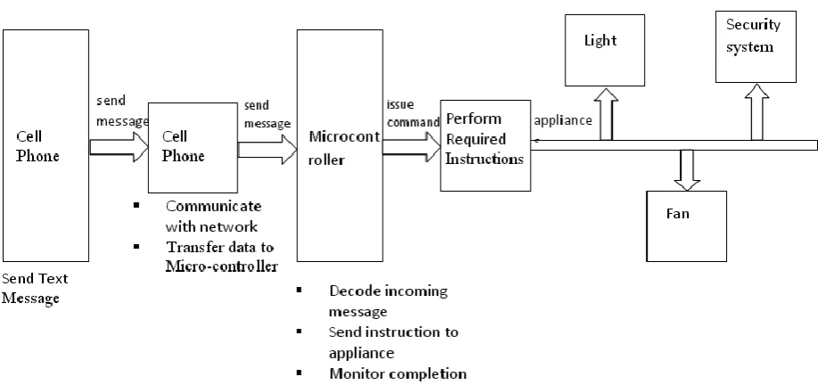
System Operation Flow
Figure 6 shows the operation flow pattern of the whole system, while figure 7 is the operating flow cart. For the activation of the four output relays which are connected to various devices; the following text messages are sent via the user mobile phone to the SIM on the project module.
If the appliance is connected to the normally open terminal of the relay, the connected appliance(s) will remain inactive until the relay(s) is energized.
*CX# to close (ON) the relay. *OX# to open (OFF) the relay.
where: X stands for the number of the relay (i.e. 1, 2, 3 and 4).
If the appliance is connected to the normally closed terminal of the relay, the connected appliance(s) will be active when the relay is not energized. Consequently the text command will perform the reverse function.
*CX# to close (OFF) the relay. *OX# to open (ON) the relay.
23
MC: Decision on
the message ON/HIGH or OFF/LOW?
START
Mobile Station (MS) Initialization
Sagem My X 5 –2 (SMS) Initialization
MC: Reading, Interpretation & Processing of Message Received
MicroController (MC) (Receives Information)
LOW
HIGH
Corresponding Outputpin is triggered by the MC as specified by the message
Corresponding output drives each relay switch
MC read message again to verify if acknowledgement is specified.
Is acknowledgement
High or Low?
LOW
MC sends message based on status of each output pin to the original source i.e. user’s phone (appliance monitoring)
STOP
24
TESTINGTo activate the relays and the subsequent powering of the load connected, the following text codes were sent through a cell phone to the device: *C1#, *C2#, *C3#, *C4#. When each of this code was sent one at a time, each of the respective relay (relay1, relay2, relay3 and relay4) made a mechanical sound (contact) and subsequent powering of the device connected.
Similarly, when the code *O1#, *O2#, *O3#, *O4# were sent to the device, each of the relays powered OFF. To establish the reliability of the system, the system was left connected on to the mains supply for a period of 720 hours with a minimum of 24 messages per day sent at various locations varying from 1km to 1000km distance. The reliability was evaluated to be 97%.
CONCLUSION
A short message service over a GSM network was exploited for the monitoring and controlling of electrical appliances and devices. The sent SMS is stored in the mobile station, decoded by the micro-controller and then the required control signal is generated and sent to the intermediate hardware that was designed according to the command received in form of the sent message. SAGEM phone set (MyX5-2) was selected for the implementation. The system designed and implemented was found to be very reliable.
REFERENCES
Alkar, A.Z., & Buhur, U. (2005): An Internet Based Wireless Home Automation System for Multifunctional Devices, IEEE Consumer Electronics, 51(4), 1169-1174. Retrieved from http:www.thaieei.com/embedded/pdf/
automation/20022.pdf., August 2011.
Ciubotaru-Petrescu, B., Chiciudean, D., Cioarga, R., & Stanescu, D. (2006): Wireless Solutions for Telemetry in Civil Equipment and Infrastructure Monitoring, 3rd Romanian-Hungarian Joint Symposium on Applied Computational Intelligence (SACI) May 25-26, 2006. Retrieved from http://www.bmf.hu/ conferences/saci2006/Ciubotaru.pdf.
Conte, G. & Scaradozzi, D. (2003): Viewing home automation systems as multiple agents systems, RoboCUP2003, Padova, Italy. Retrieved from http://www.robosiri.it/
ROBOCUP_2003/ROBOCUPSITOSIRI/ articles/pdf/Conte.pdf.
Delgado, A.R., Picking, R., &Grout, V. (2006): Remote-controlled home automation systems with different network technologies. Proceedings of the 6th International Network Conference (INC2006), University of Plymouth, 11- 14 July 2006. Pp. 357-366. Retrieved from
http://www.newi.ac.uk/groutv/papers/p5.pdf
Hillebrand, F.(2001): „GSM and UTMS, the creation of Global mobile communication’. Wiley, Retrieved from http//www.gsmhistory.org August 2011.
Jawarkar, N. P., Ahmed, V., Ladhake, S. A. & Thakare, R. D. (2008): Micro-controller based Remote Monitoring using Mobile through Spoken Commands, Journal Of Networks, 3(2), pp. 58-63. Retrieved from
http://www.academypublisher.com/jnw/vol03/n o02/jnw03025863.pdf.
Khiyal, M.S.H., Khan, A. & Shehzadi, E. (2009): “SMS based wireless Home Appliance Control System (HACS) for automating
appliances and security”, Issues in Informing Science and Information Technology, Volume 6, 2009, pp 887 – 894.
Murthy, M. V. R. (2008): Mobile based primary health care system for rural India. W3C workshop on Role of Mobile Technologies in Fostering Social Development, June 2008.
Potamitis, I., Georgila, K., Fakotakis, N., & Kokkinakis, G. (2003): An integrated system for smart-home control of appliances based on remote speech interaction, EUROSPEECH 2003, 8th European Conference on Speech Communication and Technology, pp. 2197-2200, Geneva, Switzerland, Sept. 1-4, 2003. Retrieved from http://www.wcl.ee.upatras.gr/ ai/papers/potamit is14.pdf.