Secured Voice Frequency Signal Transmission in 5G
Compatible Multiuser Downlink MIMO NOMA Wireless
Communication System
Md. Humaun Kabir1,*, Jinia Rahman2, Shaikh Enayet Ullah2
1Department of Computer Science and Engineering, Pundra University of Science and Technology, Bogura, Bangladesh 2Department of Applied Physics and Electronic Engineering, University of Rajshahi, Rajshahi, Bangladesh
Abstract
In this paper, we investigate the performance of 2×2 multi antenna configured NOMA wireless communication system. The simulated system under investigation incorporates various types of channel coding schemes (LDPC, (3, 2) SPC and Repeat and Accumulate) and two types of low order modulation techniques (QPSK and QAM). We propose an improved ML decoding based QR channel factorization aided SIC (QR-SIC) technique and it is implemented on encrypted audio signal transmission in a hostile fading channel. Numerical simulation results show that the presently considered simulated system is very much robust and effective in retrieving audio signal under utilization of Repeat and Accumulate channel coding and QAM digital modulation techniques.Keywords
5G, NOMA, MIMO, QR-SIC, ML decoding, LDPC, (3, 2) SPC and RA1. Introduction
In view of consideration of increasing demand by mobile radio customers for multimedia services, higher data rates andbandwidth availability as well as anticipated traffic related to the Internet of Things (IoT), the fifth Generation (5G) /Beyond 5G (B5G) wireless communication systems will emerge to meet up unprecedented demands beyond the capability of previous generations of wireless communication networks. The 5G networks will promote the continued evolution of the way human interacting information and provide users with ultimate experience through more immersive services such as 3D connectivity (aircraft and drone), Ultra High Definition (UHD), 3D video, Online gaming applications, Augmented and virtual reality, Video/photo sharing in stadium/open air gathering, Mobile cloud/desktop cloud, Tactile Internet, Collaborative robots etc. [1-2]. OFDMA is commonly used as the multiple access technique in the present wireless communication systems which can provide concurrent interference free transmission to multiple users with orthogonal subcarriers. The main drawback of OFDMA is that it does not generally achieve the highest possible data rate for a given error probability [3-6].
* Corresponding author:
[email protected] (Md. Humaun Kabir) Published online at http://journal.sapub.org/ijnc
Copyright©2018The Author(s).PublishedbyScientific&AcademicPublishing This work is licensed under the Creative Commons Attribution International License (CC BY). http://creativecommons.org/licenses/by/4.0/
distances as the available feedback, to UAVs serving as aerial base stations (BSs). Through their extensive simulation works, a comprehensive framework was developed for deriving achievable outage probabilities and sum rates rigorously with implementation of distance feedback based NOMA strategy. NOMA technique can be applied to improve the achievable sum rate of multiple-input multiple-output (MIMO)-based multi-user visible light communication (VLC) systems. At [11], the authors proposed a normalized gain difference power allocation (NGDPA) method first through exploiting users' channel conditions for consideration of efficient and low-complexity power allocation in indoor MIMO-NOMA-based VLC systems. With employment of NOMA with the proposed NGDPA method, achievable sum rate of the 2×2 MIMO-VLC system was improved significantly. In [12], the authors made investigative study on the performance of advanced NOMA using experimental trials in outdoor using 2×2 open loop MIMO and 4×2 closed-loop MIMO. The results of their work confirmed that NOMA was capable of providing a maximum of 2.3 times more gains as compared to SU-MIMO for the case of 3-UE when combined with 4×2 closed-loop MIMO. At [13], the authors investigated on the joint power allocation and modulation optimization in two-user NOMA channels using finite-alphabet inputs with perfect CSI. Their simulation results showed that their proposed approach based on the error-rate criterion outperformed as compared to some existing NOMA schemes based on perfect SIC assumption. In [14], the authors utilized cyclostationarity based equalization scheme in power domain NOMA system for signal detection. Results of their simulation works confirmed the suitability of implemented technique in under low signal-to-noise ratio (SNR) environment. In this present study, we have presented simulation results for MIMO NOMA system under scenario of utilizing mainly encryption, different modulation, several channel coding, and successive user interference reductions techniques.
2. Signal Processing Techniques
In our present study various signal processing schemes have been used. A brief overview of these schemes is given below:
2.1. ML Decoding Based QR-SIC Algorithm
We assume that the base station is equipped with M transmitting antennas and each individual user is equipped with Nreceiving antennas (M ≤ N). With perfect channel state information (H), the received signal at 𝑘𝑡ℎ user can be
represented as:
Yk= Hk X + Wk = Hk ∑PkSk,v+ Wk (1)
Where, Hk is the complex channel coefficient between
kth user and base station, P
k is the allocated power for the
kth user, S
k,v is the transmitted symbol for kth user from
vth transmitting antenna and the term W
k denotes the
receiver Gaussian noise including inter-cell interference at the receiver of kth user. For the case of two users (k = 1, 2),
assume that UE1 is a cell-center user (near user) and UE2 is a cell-edge user (far user), the received signals at user #1 and user #2 are given by:
Y1= H1 X + W1 (2)
Y2= H2 X + W2 (3) Where, the transmitted signal X is formed from summing up of simultaneous transmission of two spatially multiplexed consecutive complex symbols of each user (X1
and X2) in one time slot and can be written as:
X = X1+ X2
= �P1S1+ �P2S2
=�P1�SS11,,12�+�P2�SS22,,12� (4)
Where, S1 and S2 are transmitted signals for UE1 and
UE2 prior to power allocation, signal components S1,1 of
UE1 and S2,1 of UE2 are transmitted from first transmitting
antenna and S1,2 of UE1 and S2,2 of UE2 are transmitted from
second transmitting antenna. The P1 (20% of total power)
and P2 (80% of total power) are allocated power to user #1
and user #2 respectively. On QR matrix decomposition of channel coefficient of kth user, we can write,
Hk= QkRk (5)
Where, Qk is N×M unitary matrix, QHkQk= I, Rk is
M×M upper triangular matrix. After multiplying both sides of equation (1) with complex conjugate transformed of Qk,
we get:
QHk Yk= Rk X + QkHWk (6)
With utilization of Maximum Likelihood (ML) signal detection technique, we can write,
𝑋�𝑘 = arg min ( ‖Yk−Rk X ‖2 )
= arg min ( ∑ �Mi=1Yi− ∑𝑀𝑗=𝑖Ri,j𝑋𝑗�2) (7)
Where, ‖.‖2 is indicative of square of Frobenius norm
of matrix, Ri,j is the (i, j)th component of R and | . |
implies the absolute value [15-16].
2.2. LDPC Channel Coding
Low-density parity-check (LDPC) code invented by Gallager is a linear block code with its parity-check matrix H
containing only a few 1’s in comparison to 0’s. Bilateral Tanner graph is used to make graphical representation of LDPC codes. In bilateral Tanner graph, nodes are grouped into one set of n bit nodes (or variable nodes) and the other set of m check nodes (or parity nodes). Check node i is connected to bit node j in case of any elemental value of the parity matrix unity. The decoding operates alternatively on the bit nodes and the check nodes to find the most likely codeword c that satisfies the condition cHT= 0. In iterative
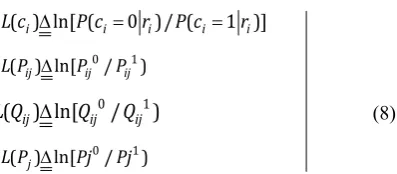
vector r, the log-likelihood ratios (LLRs) instead of probability can be defined as:
( ) ln[ (i i 0 )/ (i i 1 )]i L c ∆ P c = r P c = r
0 1
( ) ln[ij ij / ij ) L P ∆ P P
0 1
( ) ln[ij ij / ij )
L Q ∆ Q Q (8)
0 1
( ) ln[j / ) L P ∆ Pj Pj
Where, ln(.) represents the natural logarithm operation. The bit node j is initially set with an edge to check node i:
2
( ) ( ) 2 /ij i i
L P =L c = r σ (9) In message passing from check nodes to bit nodes for each check node i with an edge to bit node j; L(𝑄𝑖𝑗) is updated as:
(Qij) ) j i j [ j ( i j)] ( 1,2,..., ; )
L =
∏
′α ϕ′∑
′ϕ β ′ j′= n j′≠ j (10)where, α ∆ij sign[L(P )] andij β ∆ij [L(P )].ij The φ function is defined as:
)]
1
e
/(
)
1
e
ln[(
)]
2
/
x
ln[tanh(
)
x
(
=
−
=
x+
x−
φ
(11)From bit nodes to check nodes for each bit node j with an edge to check node i; L(Pj) is updated as:
( ) ( )i i ( ) ( 1,2,..., ; )
L Pij =L c +
∑
′ L Qij i′= m i′≠i (12)Decoding and soft outputs: for j = 1,2,3, n; L(Pj) is updated as:
( ) ( )i i ( ) ( 1,2,..., )
L Pj =L c +
∑
L Pij i= m (13) < = else 0 0 ) P ( L if 1 c j
i (14)
If cHT = 0 or the number of iterations reaches the
maximum limit [17], the LDPC channel coding and decoding in MATLAB have been executed with the aid of programs available in website at [18].
2.3. Repeat and Accumulate (RA) Channel Coding
The RA is a powerful modern error-correcting channel coding scheme. In such channel coding scheme, all the extracted binary bits from the audio has been arranged into a single block and the binary bits of such block is repeated 2 times and rearranged into a single block containing binary data which is double of the number of input binary data.
2.4. (3, 2) Single Parity Check Channel Coding
In (3, 2) Single Parity Check (SPC) channel coding scheme, the binary bits are grouped into very small sized message block u consisting of two consecutive bits. The
code is generated with addition of a single parity bit to the message u = [u0, u1] so that the elements of the resulting code word x = [x0, x1, x2] are given by x0 = u0, x1 = u1 and x2 = u0 Ξ u1 where, the symbol Ξ used here is indicative of the sum over GF (2) [19].
2.5. Data Scrambling
The transmitted voice frequency signals are encrypted in this simulation work for secured communication. The binary converted data from audio signal of each of the two users are grouped individually with each group containing 1 byte (8 bits) binary data. Each grouped binary data as plain text are encrypted with identical secret key of bit length 8 through performing XOR operation to produce encrypted/scrambled binary data [20].
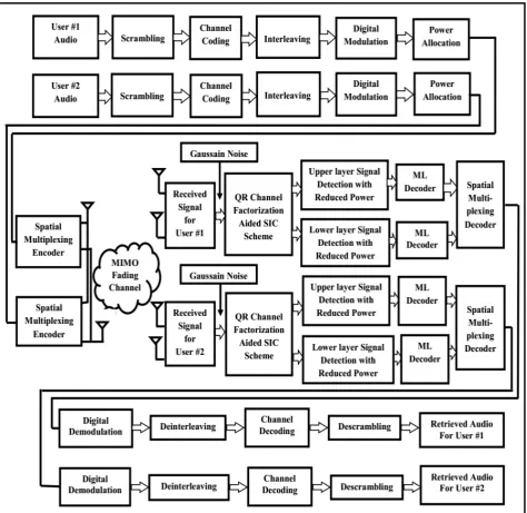
3. System Model
Figure 1. Block diagram of 5G compatible multiuser downlink MIMO NOMA wireless communication system
4. Results and Discussion
In this section, we present a series of simulation results using MATLAB to illustrate the significant impact of various types of channel coding and modulation techniques on MIMO NOMA Wireless Communication system performance in terms of bit error rate (BER). It is assumed that the channel state information (CSI) of MIMO fading channel is available at the receiver. The proposed model is simulated to evaluate the quality of the system performance with considering the following parameters presented in the Table 1.
Table 1. Simulation Parameters
Parameters Types
Data Type Audio Signal
No. of samples 8000
Sampling Frequency (Hz) 8000 No. of bits per sample 8
No. of user 2
Antenna configuration 2x2 MIMO Channel Channel Coding LDPC, (3, 2) SPC and RA Digital Modulation QPSK and QAM
Signal Detection Scheme ML decoding based QR-SIC Algorithm
SNR 0 to16 dB
Figure 2. BER performance of LDPC channel encoded MIMO NOMA Wireless communication system with QPSK and QAM digital modulation scheme for audio data transmission
Figure 3. BER performance of (3, 2) SPC channel encoded MIMO NOMA Wireless communication system with QPSK and QAM digital modulation
Figure 4. BER performance of Repeat and Accumulate channel encoded MIMO NOMA Wireless communication system with QPSK and QAM digital modulation scheme for audio data transmission
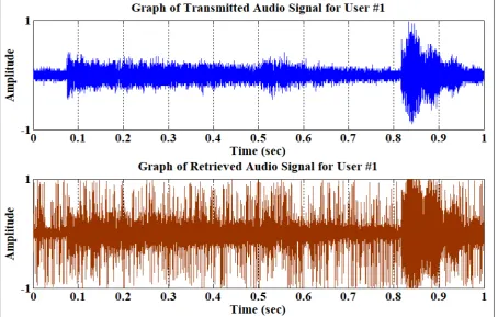
Figure 5. Transmitted and retrieved audio signals for user #1 of MIMO NOMA wireless communication system under implementation of Repeat and
Figure 6. Transmitted and retrieved audio signals for user #2 of MIMO NOMA wireless communication system under implementation of Repeat and Accumulate channel coding with 4-QAM digital modulation at 10 dB SNR
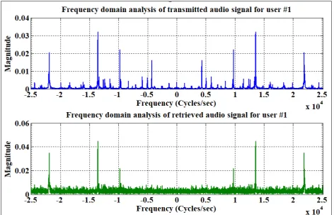
Figure 7. Frequency spectrum of transmitted and retrieved audio signals for user #1 of MIMO NOMA wireless communication system under
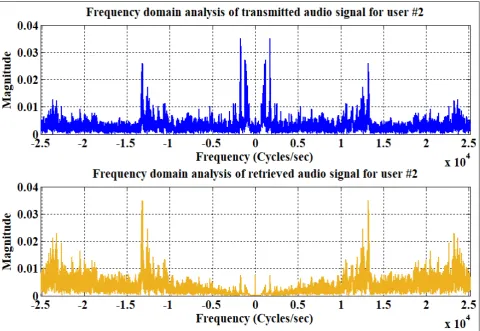
Figure 8. Frequency spectrum of transmitted and retrieved audio signals for user #2 of MIMO NOMA wireless communication system under implementation of Repeat and Accumulate channel coding with 4-QAM digital modulation at 10 dB SNR
The performance of the simulated MIMO NOMA wireless communication system in terms of estimated bit error rate (BER) in case of user #1 and user #2 under implementation of LDPC channel coding scheme with QPSK and QAM digital modulation schemes for audio signal transmission are graphically depicted in Figure 2. It is quite noticeable from Figure 2 that the estimated BER values decrease slowly for both users under utilization of QAM digital modulation technique which portraits a better BER performance in QAMas compared to QPSK at different signal to noise ratio (SNR) values ranging from 0 dB to 16 dB. Under consideration of a typically assumed SNR value of 4 dB for user #1, the estimated BER values are 0.4438 and 0.3168 which is indicative of system performance improvement of 1.46 dB in QAM as compared to QPSK. On identical scenario for user #2, the estimated BER values are found to have values of 0.4103 and 0.1438 which implies a system performance improvement of 4.55 dB. The overall system performance is not compatible for user #1 as low power (20%) is assigned as compared to user #2 (80%). At such 20% BER, a SNR gain of 6 dB is achieved with QAM for user #2 as compared to user #1.
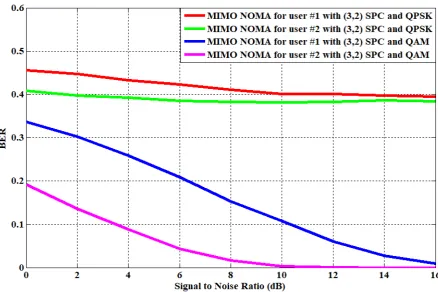
It is keenly observable from the graphical illustration presented in Figure 3 that the simulation system shows comparatively better performance with QAM and (3, 2) SPC channel coding technique. It is quite noticeable from Figure
3 that in case of QPSK, the estimated BER performance values in case of both users are not satisfactory. For user #1 under consideration of a typically assumed SNR value of 6 dB, the estimated BER values are 0.4243 and 0.2095 with utilization of QPSK and QAM which implies a system performance improvement of 3.06 dB. In case of user #2 for identical scenario, the estimated BER values are 0.3859 and 0.0439 which is indicative of system performance improvement of 9.44 dB. The overall system performance is suitable for user #2 as more power (80%) is assigned to it as compared to user #1 (20%). At 10% BER, a SNR gain 6.8 dB is achieved with QAM for user #2 as compared to user #1.
achieved with QAM digital modulation for user #2 as compared to user #1. In Figure 5, the transmitted and retrieved audio signals for user #1 under implementation of Repeat and Accumulate channel coding with 4-QAM digital modulation at 10 dB SNR value have been presented. Similarly, in Figure 6, the transmitted and retrieved audio signals for user #2 under implementation of Repeat and Accumulate channel coding with 4-QAM digital modulation at 10 dB SNR value have been presented. The presented graphical illustrations are clearly representative of assigning power. The spectral graphs for user # 1 and user #2 are presented in Figure 7 and Figure 8 respectively. Due to assigning more power for user #2, the quality of its retrieval audio signal is reasonably acceptable.
5. Conclusions
In this paper, a comprehensive study has been undertaken on the performance evaluation of MIMO NOMA wireless communication system for transmission of secured audio signal. Numerical results ratifies the significance of exploiting digital modulation, ML decoding based QR channel factorization aided SIC (QR-SIC)and different channel coding schemes. In the context of system performance, it can be concluded that the implementation of QAM digital modulation technique in Repeat and Accumulate channel coding scheme provides satisfactory result for such a 5G compatible downlink multiuser MIMO NOMA Wireless Communication System.
REFERENCES
[1] Wei Xiang, Kan Zheng, Xuemin (Sherman) Shen, 2017: 5G Mobile Communications, Springer International Publishing, Switzerland.
[2] Shahid Mumtaz, Jonathan Rodriguez and Linglong Dai, 2017: mmWave Massive MIMO-A Paradigm for 5G, Academic Press, an imprint of Elsevier Inc., United Kingdom.
[3] M. Salem, A. Adinoyi, M. Rahman, H. Yanikomeroglu, D. Falconer, Y. D. Kim, E. Kim, and Y. C. Cheong, 2010: An Overview of Radio Resource Management in Relay Enhanced OFDMA-Based Networks, IEEE Communications Surveys and Tutorials, vol. 12, pp. 422–438.
[4] D. Lopez-Perez, X. Chu, and J. Zhang, 2012: Dynamic Downlink Frequency and Power Allocation in OFDMA Cellular Networks, IEEE Transactions on Communications, vol. 60, pp. 2904–2914.
[5] T. Novlan, R. Ganti, A. Ghosh, and J. Andrews, 2011: Analytical Evaluation of Fractional Frequency Reuse for OFDMA Cellular Networks, IEEE Transactions on Wireless Communications, vol. 10, pp. 4294–4305.
[6] A. Hamza, S. Khalifa, H. Hamza, and K. Elsayed, 2013: A Survey on Inter-Cell Interference Coordination Techniques in
OFDMA-Based Cellular Networks, IEEE Communications Surveys and Tutorials, vol. 15, pp. 1642–1670.
[7] Xin Su, HaiFeng Yu, Wansoo Kim, Chang Choi and Dongmin Choi, 2016: Interference cancellation for non-orthogonal multiple access used in future wireless mobile networks, EURASIP Journal on Wireless Communications and Networking.
[8] Zhanji Wu, Kun Lu, Chengxin Jiang, Xuanbo Shao, 2018: Comprehensive Study and Comparison on 5G NOMA Schemes, IEEE Access, vol.6, pp. 18511 – 18519.
[9] Qingqing Wu, Wen Chen, Derrick Wing Kwan Ng, Robert Schober, 2018: Spectral and Energy-Efficient Wireless Powered IoT Networks: NOMA or TDMA?, IEEE Transactions on Vehicular Technology, vol. 6, pp. 6663 – 6667.
[10] Nadisanka Rupasinghe, Yavuz Yapici, Ismail Guevenc, 2018: Performance of Limited Feedback Based NOMA Transmission in mmWaveDrone Networks, In proceeding of IEEE International Conference on Communications Workshops (ICC Workshops), pp.1-6.
[11] Chen Chen, Wen-De Zhong, Helin Yang, Pengfei Du, 2018: On the Performance of MIMO-NOMA-Based Visible Light Communication Systems, IEEE Photonics Technology Letters, vol. 30, no.4, pp. 307 – 310.
[12] Anass Benjebbour and Yoshihisa Kishiyama, 2018: Combination of NOMA and MIMO: Concept and Experimental Trials, NTT DOCOMO, INC, pp-433-438. [13] Benjamin K. Ng and Chan Tong Lam, 2018: Joint Power and
Modulation Optimization in Two-user Non-orthogonal Multiple Access Channels: a Minimum Error Probability Approach, IEEE Transactions on Vehicular Technology. [14] Jayanta Datta and Hsin-Piao Lin, 2018: Detection of Uplink
NOMA Systems Using Joint SIC and Cyclic FRESH Filtering, The 27th Wireless and Optical Communications Conference (WOCC2018), IEEE.
[15] Jinho Choi, 2016: On the Power Allocation for MIMO-NOMA Systems with Layered Transmissions, IEEE transactions on wireless communications, vol. 15, no.5pp. 3226-3237.
[16] Md. Humaun Kabir and Shaikh Enayet Ullah, 2017: Performance Analysis of Multiuser Downlink MIMO NOMA Wireless Communication System on Color Image Transmission, Global Journal of Computer Science and Technology: (E) Network, Web & Security, Vol. 17, pp. 13-23.
[17] Yuan Jiang, 2010: A Practical Guide to Error-Control Coding Using MATLAB, Artech House, Norwood, MA, USA. [18] ldpc - bsnugroho - Google Sites, Retrieved from
https://sites.google.com/site/bsnugroho/ldpc.
[19] Giorgio M. Vitetta, Desmond P. Taylor, Giulio Colavolpe, Fabrizio Pancaldi and Philippa A. Martin, 2013: Wireless Communications Algorithmic Techniques. John Wiley and Sons Ltd, United Kingdom.