World Maritime University
The Maritime Commons: Digital Repository of the World
Maritime University
World Maritime University Dissertations Dissertations
1999
Proposal of a contingency plan for oil spill response
in Maputo Bay
Martnho Fernando Mafumo World Maritime University
Follow this and additional works at:http://commons.wmu.se/all_dissertations Part of theEnvironmental Studies Commons
Recommended Citation
Mafumo, Martnho Fernando, "Proposal of a contingency plan for oil spill response in Maputo Bay" (1999).World Maritime University Dissertations. 315.
WORLD MARITIME UNIVERSITY
Malmö, Sweden
PROPOSAL OF A CONTINGENCY PLAN FOR
OIL SPILL RESPONSE IN MAPUTO BAY
By
MARTNHO FERNANDO MAFUMO
Mozambique
A dissertation submitted to the World Maritime University in partial fulfilment of the requirements for the award of the degree of
MASTER OF SCIENCE
in
MARITIME SAFETY AND ENVIRONMENTAL PROTECTION
(Administration)
1999
I certify that all the material in this dissertation that is not my own work has been
identified, and that no material included for which a degree has previously been
conferred on me.
The contents of this dissertation reflect my own personal views, and are not necessarily
endorsed by the University.
... (Signature)
... (Date)
Supervised by:
Name: Professor Fernando Pardo
...
Office: World Maritime University
Assessor:
Name: Captain Jan Horck
...
Office:World Maritime University . Institution/organisation: World Maritime University
Co-assessor:
Name: Captain Miguel Laburu
...
Office: Centro de la Seguridad Maritima Integral "Jovellanos"
Acknowledgements
This paper was developed during my period of study at the World Maritime University,
with help and selfless of various people. I would like to take this opportunity to give
thanks to the following for their worthy support.
To the Mozambican National Maritime Authority (SAFMAR), for awarding me the
scholarship to pursue these studies.
Appreciation for academic guidance provided by various staff at WMU, especially the
MSEP team, English Department and the Library staff.
Special appreciation is extended to Professor Fernando Pardo, for his tireless and careful
supervision.
Finally, I wish to express my deep gratitude and sincere thanks to my mother, relatives
and friends for their encouragement and solidarity during the time spent away from
ABSTRACT
Title of Dissertation: PROPOASAL OF A CONTINGENCY PLAN FOR OIL SPILL RESPONSE IN MAPUTO BAY.
Degree: MSc
The need for an oil spill contingency plan in Mozambique was first initiated by the
Central Government at the end of the 1980s. It was re-emphasised in 1992 after the
"Katina P" incident, which occurred within the Maputo Bay.
The development of this plan, therefore, is consistent with the intent of the
Government of Mozambique which recommended, as one of the ultimate goals for
SAFMAR, " to develop a co-ordinated national contingency plan so that there will
be an effective response to any oil spill".
The aims and objectives of the contingency plan are to provide a safe, systematic and
integrated response to oil pollution incidents that may occur within the bay. An
analysis of the required level of preparedness, the necessary response capabilities,
and the resources that should be available to combat oil spill in the Bay of Maputo
has made. Included in this plan are the oil spill reporting procedures that must be
followed to keep the supervisory and management personnel informed about any oil
spill incidents, and the steps to be taken for immediate action in case of such an
event. Also, included in this dissertation is the needed organisational structure of an
TABLE OF CONTENTS
Declaration ii
Acknowledgements iii
Abstract iv
Table of Contents v
List of Abbreviations ix
List of Figures xi
List of Table xii
I. INTRODUCTION 1
II. OIL POLLUTION 4
2.1.Introduction 4
2.1.1.What is oil pollution 5
2.2. Sources of oil pollution 6
2.2.1. Marine transportation losses 6
2.2.2. Offshore oil production 6
2.2.3. Tanker accidents 7
2.2.4. Atmospheric fallout 7
2.2.5. Municipal, industrial and run off 7
2.3.Characteristics of oil 8
2.3.1. Density (specific gravity) 8
2.3.2. Distillation characteristics 8
2.3.3. Viscosity 9
2.3.4. Pour point 9
2.3.5. Asphaltene content 9
2.4. Fate of marine spills 9
2.4.1. Weathering process 10
2.4.1.1. Spreading 10
2.4.1.2. Evaporation 11
2.4.1.3. Dispersion 11
2.4.1.5. Dissolution 12
2.4.1.6. Oxidation 13
2.4.1.7. Sedimentation 13
2.4.1.8. Biodegradation 13
2.5. Forecasting the Movement of oil slicks 14
2.5.1. Aerial surveillance 14
2.5.2. Oil spill assessment 15
2.6. Effect of oil spill 15
2.6.1. Impact of oil on coastal activities 15
2.6.2. Impact on industry 15
2.6.3. Impact of oil on specific marine habitat 16
2.6.4. Biological effects 16
2.6.5. Impact of oil on fisheries and marineculture. 17
III. CONTAINMENT, RECOVERY EQUIPMENT AND USE OF DIEPERSANTS 18
3.1. Introduction 18
3.2. Containment equipment 18
3.2.1. Booms 18
3.2.1.1. Solid flotation booms 20
3.2.1.2.Inflatable booms 20
3.2.1.3. Fence booms 20
3.2.1.4. Bubble barriers 21
3.2.1.5. Sorbent booms 21
3.2.1.6. Improvised booms 21
3.2.2. Common boom failure during operation 22
3.2.2.1. Submergence failure of the booms 22
3.2.2.2. Splash-over failure 22
3.2.2.3. Drainage failure 23
3.2.2.4. Entrainment failure 24
3.2.3. Deployment of booms 24
3.2.3.1. Standard boom configuration for open sea operations 25
3.2.3.2. Standard boom configuration near shore and in rivers 25 3.3. Recovery equipment 26
3.3.1. Skimmers 26
3.3.2. Sorbents 29
3.4. Use of dispersant 30
3.4.1. Types of dispersants 30
3.4.2. Application of dispersants 31
IV. CLEAN-UP STRATEGY AND CLEAN-UP TECHNIQUES 33
4.1. Clean-up strategy 33
4.1.1. Assessment of the problems 33
4.2. Clean-up techniques 34
4.2.1. Bioremediation 37
4.3. Disposal of oil and debris 37
4.4. Disposal options 40
4.4.1. Landfill disposal 40
4.4.2. Land-farming 41
4.4.3. Open burning 41
4.4.4. Process incineration 42
4.4.5. Reprocessing 42
4.4.6. Reclaiming/Recycling 42
V. CONTINGENCY PLANNING 44
5.1. Scope and content of a contingency plan 44
5.2. Strategy 44
5.2.1. Assessment of spill risk 45
5.2.2. Movement and persistence of oil spill 45
5.2.3. Resources at risk from a spill 45
5.2.4. Selection of the response techniques 46
5.2.5. Outline of the response organisation 46
5.2.6. Training and review procedures. 47
5.3. Operational plan 48
5.3.1. Notification 48
5.3.2. Evaluation 49
5.3.3. Response decisions 49
5.3.4. Clean-up operations 50
5.3.5. Termination of clean-up operations 51
5.3.6. Formulation of claims 52
VI. MAPUTO BAY CONTIGENCY PLAN 54
6.1. Introduction 54
6.2. Objectives 55
6.3. Location of Maputo Bay and Environmental Considerations. 56
6.4. Risk assessment 57
Section I: Basic criteria 57
6.I.1. Definitions 57
6.I.3. Criteria for activation of the CP 60
6.I.4. Mechanism of activation of Maputo Bay CP 60
6.I.5. Organs; entities and companies party to the Maputo Bay CP 61
6.I.6. Responsibilities and response organisation 63
6.I.7. Training, periodical exercises plan and plan revision 64
Section II. General operational procedures 64
6.II.1. Notification 64
6.II.2. Immediate action to be taken by the Co-ordinator Centre 65
6.II.3. How to activate different organs of the plan 65
6.II.4. Evaluation of the situation and setting up of the operational 66
6.II.5. Protection of sensitive areas 67
6.II.6. Introduction of changes to the operational plan 67
6.II.7. Communication 67
6.II.8. Public relations 68
Section III. Response decision 68
6.III.2.Special measures foe sensitive areas and criteria for their prioritisation 71
6.III.3. Selection of clean-up techniques 71
6.III.4. Initiation of response 72
6.III.5. Report on the situation 72
6.III.6. Termination of response 72
Section IV. Management of resources and services 73
6.IV.2. Control of dispenditures 73
Section V. National legislation 73
6.V.1. International Conventions 74
Section VI. Legal aspects 75
6.VI.1. Presentation of claims 75
6.VI.2. Information required from the claimants 76
VII. CONCLUSION AND RECOMMENDATIONS 77
7.1.Conclusion 77
List of Abbreviations
CC- Co-ordinator Centre
CLC 69- International Convention on Civil Liability for Oil Pollution Damages, 1969
COW- Crude Oil Washing
CP- Contingency Plan
EC- Emergency Committee
EEZ- Economic Exclusive Zone
GASAMP- United Nation Joint Group of Experts on Scientific Aspects of Marine Pollution
GT- Gross Tonnage
HLB- Hydrophilic Lipophilic Balance
IMO- International Maritime Organisation
ITOPF- International Tanker Owners Pollution Federation
LOT- Load on Top
MARAD- Maritime Administration
MARPOL 73/78- International Convention for the Prevention of Pollution from Ships, 1973/78
OC- Operational Co-ordinator
OILPOL 54- International Convention for the Prevention of Pollution of the Sea by Oil, 1954
OPRC 90- International Convention on Oil Pollution Preparedness Response and Co-operation, 1990
ORR- Oil Recovery Rate
OSC- On-Scene Co-ordinator
RE- Recovery Efficiency
SAFMAR- Mozambican National Maritime Safety Authority
SBT- Segregated Ballast Tank
TE- Throughput Efficiency
List of Figures
Figure 1 Submergence failure of the booms 22
Figure 2 Splash-over failure of the booms 23
Figure 3 Drainage failure of the booms 23
Figure 4 Entrainment failure of the boom 24
Figure 5 Chart for waste separation 39
Figure 6 Chart representing the link between different CPs 59
Figure 7 Organisational structure 62
List of tables
Chapter I
The merit of a civilisation is not measured
With what it can create, but with what it can
Preserve. (Edouard Herriot)
1.1. Introduction
Mozambique is a coastal state with a coastline of about 2470km, running from the
north to south, and the Mozambique Canal is one of the preferred routes for oil
transportation in the world. About 300 oil tankers pass through the canal daily, which
makes it a high-risk waterway.
During the last 8 years two serious accidents have occurred in the canal involving two
tankers, namely; Katina P. and Shin Kakogawa Maru and one of the accidents affected
greatly the Maputo Bay.
The accidents brought out the problem of an absence of a contingency plan for oil spill
prevention and response, as well as the lack of updated legislation regulating the
environmental issues.
Since then the government of Mozambique has been taking steps towards a solution of
the problem. One of the steps was the creation of a competent maritime authority with
accession of Mozambique to the international conventions to which it is not yet part,
such as, MARPOL and OPRC.
Because preparation of the contingency plan has been delayed, and concerns among
different parts interested in the issues have been arising, the author of this paper found
it necessary to give a contribution in the preparation of a contingency plan covering the
Maputo Bay, as part of the national contingence plan.
The objective is to elaborate and propose a prototype contingency plan that can be used
over the entire coastline, depending on the circumstances of each area.
The paper is divided into seven chapters. In the second chapter are outlined the main
sources of oil pollution and the environmental, economical and social implications of
an oil spill.
The third chapter gives the overview of the existing containment and recovery
equipment as well as their purpose and use. Also, in this chapter the concept of use of
dispersants and their effects is developed.
The analysis of different clean-up strategies and techniques are dealt with in chapter
four, and chapter five offers an indication of what contingency planning should be and
the scope of a contingency plan.
In chapter six the proposal of the Maputo Bay contingency plan is developed as
conceived by the author having take into consideration the circumstances surrounding
Adopted approach:
a) Investigation at the WMU and Malmö city libraries.
b) Advise from professors and visiting experts.
c) Interviews of the SAFMAR, MICOA, Maputo MARAD and Oil Industry
representatives.
d) Uses of different contingencies planning at different levels.
Main constraint
The main constraint during the preparation of this paper was related to the short time
for investigation back home bearing in mind that there is no systematic organisation of
Chapter II
2.1. Oil Pollution
The world has faced oil pollution since ancient times. Natural seeps have been the
major contributor. However, pollution has never been as alarming as it seems to be
today. This is because since the industrial revolution human beings have turned to oil
for production of energy for their daily needs.
Day after day, the dependence of the world on oil as a source of energy has been
increasing, and hundreds of ships have been sailing day and night from one place to
another transporting oil and oil products. During the production and transportation
processes accidents have been taking place either at sea or in the ports. Some of these
accidents have had negative environmental, economic and social impacts.
In fact, oil pollution due to accidents was not of great concern until March 1967, when
the first major accident occurred involving the Torrey Canyon. She spilt large
quantities of oil resulting in hundreds of miles of oily beaches and the death of
thousands of seabirds (Johnston, 1976). Since than the world has realised what the real
risk of oil in daily our life is. Consequently, measures have been taken to prevent and
combat oil spills. This includes the development of equipment and techniques for oil
response, adoption of international and national regulations, the building of
contingency plans at national and international levels and the training of personnel.
2.1.1. What is oil pollution?
The task to deal with oil pollution at sea or on the shore requires to some extent the
answer of the question above. The answer is not easy, because it requires the
understanding of the three groups of material pollution, namely, native or natural
pollution, pollution caused by, but not created by, human beings, and synthetic
pollution which can be found in the sea as a consequence of human activities. On the
other hand, some of them exist naturally in the sea. Thus, it is of vital importance to
comprehend the impact of each of the three groups. Furthermore, it is necessary to be
aware of the existing difference between contamination and pollution. Sometimes it is
difficult to make a distinction because of similarities in their impacts.
According to GESAMP, " contamination is high concentration of substances in water,
sediments or organisms, i.e., concentration that are above the natural level for the area
and for the organisms" (Clark R. B. 1992).
Pollution is the introduction by man, directly or indirectly, of substances or energy to
the marine environment resulting in deleterious effects such as harm to living
resources; hazards to human health; hindrance of marine activities including fishing,
impairment of quality for use of sea water; and reduction of amenities (Clark R.B.
1992, page 6).
Or rather, contamination is an indication of deterioration of the environment, but it can
not be regarded as being pollution unless it is a result of human activities or it threatens
the environment.
For this reason, is quite difficult to distinguish damages caused by a low level of
contamination from these types of pollution.
2.2. Sources of Oil Pollution.
About 3.2 million metric tonnes of oil enter into the sea each year from different
sources. One of the essential measures in combating oil spills is to identify the sources
and how much oil or oil products each source discharges into the sea. Studies have
identified seven major sources of oil pollution, namely, marine transportation, offshore
production, tanker accidents, municipal and industrial discharge, atmospheric fallout
and run-of and natural seeps.
2.2.1. Marine Transportation Losses
Of amount mentioned above 1.47 million metric tonnes result from transportation
losses, 0.7 m tonnes of which are considered as cargo residues. However, with the
introduction of systems such as, Segregate Ballast Tank (SBT) and Crude Oil Washing
(COW), together with Load on Top (LOT) procedures, these discharges have been
diminishing significantly. To transportation losses can be included discharges of oily
bilge water and fuel oil sludge calculated in about 300,000 tonnes per annum,
generated by all types of ships.
Construction of reception facilities and strict management helps to control the
quantities of waste oil discharged into the sea from ships.
22.2. Offshore Oil Production
Offshore oil production is one of the sources under control thanks to the safety
measures adopted during the production period. However, the incidents that happen
from time to time and the spilt oil may reach about 50,000 tonnes which is not to be
ignored considering that there are many platforms all over the world. Three quarters of
that amount is linked to blowout incidents (ITOPF, 1983). The routine operations are
2.2.3. Tanker accidents
Tanker accidents are responsible for 400,000 tonnes entering the sea per annum. A
considerable part of this quantity is spilt into the ports during loading and bunkering
operations. Spills from accidents such as groundings and collisions are less than 10%
of all spills from tankers, but a quarter of these are larger than 700 tonnes.
2.2.4. Atmospheric Fallout
Burning of petroleum hydrocarbons in ships, cars, factories and other mean using oil
for energy production leads to exhaust fumes and gases into the atmosphere. Also, oil
exposed to the air volatilises into vapour. All these hydrocarbon gases and oil vapours
directly or indirectly enter the sea mixed with the atmospheric water vapour as rain or
snow.
2.2.5. Municipal, Industrial and run off
In the recent past the shipping industry lead the discharges of petroleum products into
the sea. However, nowadays thanks to the efforts of the whole maritime community
this has changed. The municipalities have taken the leadership, contributing with more
than 1.18 million tonnes.
In fact, domestic waste and sewage contains a large quantity of oil greases, which drain
into the sea. In addition, some industrial wastes contain a considerable amount of
petroleum products, which also drain into the sea. Finally, oil can be found on roads
and around car service stations and garages, being washed away by rain and draining
into the sea.
It has been more difficult to control pollution originated by the municipalities than that
national and international legislation and efforts have been made to train personnel in
order to enforce it.
2.3. Characteristics of Oil 2.3.1. Density (specific gravity)
Specific gravity shows the density of oil in relation to pure water. Usually oils are
lighter than water and have a specific gravity of less than 1. The density of oils and
petroleum products is usually expressed in terms of API gravity in accordance with the
following formula:
141.5
API= --- - 131.5
Specific gravity
Furthermore, the density can give a general indication of the other properties of the oil.
For instance, oils with a low specific gravity and a high API, tends to be rich in volatile
components and highly fluid.
2.3.2. Distillation Characteristics
The volatility of oil can be shown by the distillation characteristics. When the
temperature of oil is raised, different components reach their boiling point in turn and
are distilled. The distillation characteristics are expressed as the proportions of the
parent oil, which distils within given temperature ranges.
2.3.2. Viscosity
The viscosity of oil is its resistance to flow high viscosity oils flow with difficulty
increasing temperature. If this happens the seawater temperature and absorption of heat
from sunshine affects the viscosity of oil spilt on the sea surface.
2.3.3.Pour point
The oil's pour point is the temperature below which the oil becomes semi-solid and will
not flow. This effect is the result of the formation of an internal microcrystalline
structure. The pour point of crude oil generally varies from -35°C to +40 °C.
2.3.4. Asphaltene Content
Asphaltene plays a very important role in the formation stability of water-in-oil
emulsion. The low asphaltene oils generally do not form a stable emulsion, whilst the
high asphaltene oils do.
2.4. Fate of Marine Spills.
The marine environment is a complex natural machine capable itself to assimilate the
oil entering the world's oceans. The fact that despite the large quantity of petroleum
spilled into the seas there is little evidence of oil residues, confirms the above
suggestion.
The oil spilt on the sea surface suffers physical and chemical changes, which
sometimes leads to its disappearance from the surface. The oil's properties play an
important role when it comes to the consideration of the fate of oil in the sea. Different
oils behave differently when spilt into the sea. Frequently, distinction is made between
non-persistent and persistent oils. Non persistent oils tend to disappear and usually
clean up operations are not needed. In contrast, persistent oils take a long time to
disappear and clean-up operations are required. Gasoline, naphtha, kerosene and diesel
varying degrees of persistence depending on their physical properties and the size of
the spill.
Mostly specific gravity, distillation characteristics, viscosity and pour point have been
the main physical properties affecting the behaviour of an oil spill.
2.4.1. Weathering Process
The oil spill on the sea surface passes from different processes that lead to the change
of its composition and behaviour. These processes are called the "weathering process".
They are strictly dependent on the physical characteristics of the oil in particular the
specific gravity, viscosity and volatility; composition and chemical characteristics of
the oil; meteorological and hydrological conditions (sea state, sunlight and air
temperature); characteristics of the sea water (specific gravity, currents, temperature,
presence of bacteria, nutrients and dissolved oxygen and suspended solids).
During the process of preparation and implementation of a contingency plan for oil
response the knowledge of all these processes and how they interact is of great value.
2.4.1.1. Spreading
The spreading process is dependent on the nature of the oil and the prevailing
environmental conditions: the wind has an influence on the spreading rate, and the sea
temperature may have a very substantial effect, mostly on the highly viscous oil or
those which tend to solidify at low temperature. The volume of the spilled oil has a
major influence on the spreading process at its earlier stage, provided that the oil is
above its pour point. For instance, a large instantaneous spill is going to spread more
At the releasing time, spreading on the sea surface is rapid and predominant, decreasing
significantly until it ceases within one to ten days. It has to be mentioned that, except
in the case of small spills of low viscosity oils, spreading is not a uniform process, and
a large variation of oil thickness occurs within the slick.
2.4.1.2. Evaporation
The evaporation process is determined primarily by the volatility of the oil. The large
quantities of components with a low boiling point, the greater the evaporation. To an
extent evaporation is affected by the initial spreading rate of oil. Rough seas, high
wind speed and warm temperature increase the rate of evaporation. Volatile
components with boiling points up to 200 °C will evaporate within 24 hours. In some
cases light oil can evaporate completely.
There is a danger of fire and explosion when volatile oils are spilt in close areas.
Although, it is often possible to ignite slicks, particularly of fresh oil, it is difficult to
maintain combustion even when wicking agents are used due to the thinness of the oil
layer and the cooling effect of water.
2.4.1.3. Dispersion
The unstable state of the sea surface caused by waves and turbulence act on the slick
and break it into small droplets able to remain suspended in the water column. This
leads to the increased surface and, by this dispersed oil can enhance other processes
such as, biodegradation and sedimentation.
In this situation, every breaking wave is going to remove almost all the oil in the
wave-affected area from the surface into the water column and the rate of dispersion will be
The remaining oil fluid may spread unhindered by other weathering processes and
disperse completely within few days. Oil with high viscosity tends to form thick lenses
on the water surface, and is going to disperse very slowly. This kind of oil may persist
for some weeks.
2.4.1.4. Emulsification
When the seawater surface is agitated by wind, and specially when foam and spray
result, water is absorbed by the masses of oil spilt into the sea. Some oils can in a
short period of time absorb more than 50% of their weight in water and form brown
masses dubbed as "chocolate mousse" (Gerlach A.S. 1981).
Water-in-oil emulsion can be also being formed, particularly with heavy crude and
residual oils. The resulting emulsion contains 80% water but has a semisolid texture
(Bishop P. L. 1983). The stability of emulsion depends upon the concentration of
asphaltenes. Oil with highest content of asphaltene than 0.5% tend to form stable
emulsion "chocolate mousse", whilst those containing less are likely to disperse
(ITOPF, 1993). When the oil absorbs water it changes its colour to brown, orange or
yellow (ITOPF, 1993). With the continuation of water absorption the density of the
emulsion increases and approaches that of the water. After a long time, the mousse
may disintegrate into lumps of tars, but at the same time the chances of its washing
upon to the beaches are enhanced.
2.4.1.5. Dissolution
Some oil components will be lost from a slick by dissolution in underlying water,
although, only the low-molecular-weigh hydrocarbons and those containing polar
groups such as sulphur, nitrogen and oxygen have an appreciable solubility in water.
This situation becomes, however, more complicated when there is a complex mixture
of different compounds, which, as regards solubility, have reciprocal effects.
2.4.1.6. Oxidation
The hydrocarbon molecule once on the sea surface, breaks down into soluble products
due to the reaction with oxygen. Sunlight stimulates oxidation. When oil is
decomposed under the action of ultraviolet sunrays by oxidation, water-soluble fatty
acids and fatty alcohol are produced which are easier for micro-organisms to degrade
than the original hydrocarbons. Although, this is right during the lifetime of the slick,
the effect of oxidation on dissipation is relatively less compared to other weathering
processes.
2.4.1.7. Sedimentation
Some spilled oil ultimately sinks, often through association with suspended matter.
Several of the previously discussed processes tend to make oil denser, and thus able to
settle. Evaporation and dissolution remove the lighter fractions from semisolid
globular tar bars. These often occur as small dense particles that can sink.
Agglomeration of dispersed oil particles in the water column, followed by an uptake
onto suspended inorganic sediments, often occur particularly in coastal waters and
estuaries where many suspended sediments are present. Fine-grained clay material
may absorb large quantities of dissolved hydrocarbons from water. Once on the
bottom, tarry materials may move great distances. Much of this material may become
stranded on beaches, particularly at high tide level.
2.4.1.8. Biodegradation
Once oil is spilled on the sea surface various marine bacteria use it as a source of
they are common in chronically polluted water such as those which receive industrial
discharges and untreated sewage. The temperature and availability of nitrogen and
nutrients, mostly compounds of nitrogen and phosphorous, are likely to affect the rate
of biodegradation. The degree of weathering often has an effect on the rate of
biodegradation due to the evaporation of toxic components, which leave the slick less
bactericidal (Bishop P. L., 1983).
2.5. Forecasting the Movement of Slick.
Immediately after the oil has been spilled on the sea surface it starts to move. In order
to take appropriate response measures it is necessary to forecast the position of oil
slick. This can be achieved only if data on wind and currents are available, since both
are likely to affect the movement of the floating oil. The speed with which an oil slick
drifts under the influence of wind depends on the wind force and oil thickness.
Typically it will move at between 2% to 5% of the wind speed measured 10m above
the water surface (IMO, 1988). It has been found empirically that floating oil in open
water will move downwind at about 3% of the wind speed (ITOPF, 1983).
2.5.1. Aerial Surveillance
For an effective and successful oil response it is not enough to predict oil movement, as
there is a need of a constant verification through regular surveillance. This is possible
using an aircraft, since from the vessel it is inefficient. The changes that an oil slick
suffers are because of the combination of various processes, which can lead to a
mistake for the observer who is not familiar with them. For instance, the change of
colour from black to brown, yellow or orange contrasts with silver at the thinner parts.
To help detection of the oil slick a number of airborne sensors have been developed,
IRS, and SLAR. In some cases they can be combined. The recorded data are used in
the oil combating process.
2.5.2. Oil Spill Assessment
A well designed clean up operation can be carried out successfully if an assessment of
the oil spill is made. The assessment is mostly visual; it can be affected if there is a
potential for hiding, for example, sand, snow or vegetation such as mangroves. Careful
attention is paid to the location where the character of the shoreline changes or where
the oil coverage appears to change.
2.6. Effect of Oil Spill
A single oil spill can cause severe ecological, economic and social damages.
Depending on how is the oil spill is dealt with, its impact can be minimised or
aggravated. The effect of the oil spill depends upon where it occurs, the meteorological
conditions, type of oil, season and oceanographic conditions. The impact does not
reflect necessarily the amount of oil spilt. A little oil in a sensitive area can harm more
than a large spill on a desolate rocky shore.
2.6.1 Impact of Oil on Coastal Activities
When a clean-up operation does not take place at sea or if it does for any reason the oil
succeeds in reaching the shore, there is always an eminent threat to the recreation
activities such as bathing, boating, angling and diving. Tourism will be affected,
because of the disturbance on the coastal area.
2.6.2. Effect on Industry
Any industrial estate along the coast will be affected, particularly those using seawater
2.6.3. Impact of Oil on Specific Marine Habitat
The spilled oil on the sea surface can affect plankton. From here it is possible to disturb
the marine food web, since plankton is the base of the marine food web. The oil effect
on the marine micro-organisms depends on the type and amount of oil spilled, the
physical nature of the area (e.g. open ocean or estuarine marsh), nutritional status,
oxygen concentration, and the previous history of the area impacted with regard to
hydrocarbon exposure. Because of its high toxicity light oils will have higher
biological effects than the heavy crude.
Fish and mammals can be affected directly by petroleum, either by ingestion or oiled
prey, through the gills. Despite the fact that an overlying water column protects bentic
organisms they are not safe from oil impact. With the vertical mixing of hydrocarbon
into and throughout the water column, the impact can be felt (National Academy Press,
1985). The incorporation of oil into sediments can lead to a residence time of several
years in localised areas, with the possibilities of sub-lethal effects and tainting of
commercial species.
2.6.4. Biological effects
The overall heredity risk to marine population from oil is difficult to assess because of
unknown natural mutation rates, the occurrence of natural mutagens, and multiplication
of unrelated mutagenic population. To this can be added varying species sensitivity
and acclimation, variable cell and tissue sensitivities, and variable tissue accumulation
and metabolism. However, there is no doubt about the deleterious biological effect of
oil pollution on the marine ecosystem.
The ability of the marine population to recover from oil spills and the time taken for the
duration of disturbances and the recovery potential of each specie. In general the
process of recovery in tropical zones is faster then in cold areas.
Though the restoration process of the oiled habitat to meet its pre-spill physical
conditions is possible, the limitation of its extent is recognised. The cleaning of
mangrove and salt marsh areas requires a very careful exercise to avoid more physical
damage that can be more severe than effect of an oil spill.
On the shoreline, the oil spill effect differs from one area to another. Fore instance, on
areas of rock, sand and mud uncovered by the tide the effect is great. However,
inter-tidal organisms are likely to resist short-term exposure to adverse conditions. At the
end of the day, re-colonisation of the shore area by native species is usually rapid.
Mangrove forest, and coral reefs spread in most coastal areas of tropical zones require
special attention when an oil spill occurs. Both coral reefs and mangrove forest are
very important habitats with diversified marine biota. Furthermore, both have
commercial and social importance.
2.6.5. Impact of oil on Fisheries and Marineculture
Fish can be affected directly by petroleum, either by ingestion of oil or oiled prey,
through the uptake of dissolved petroleum compounds through the gills and other body
epithelia, though effects on fish eggs and larval survival, or through changes in the
ecosystem which support fish. Furthermore, more commercial fisheries as well as the
sport and subsistence fisheries can be affected through the contamination of gear.
Chapter III
Containment, Recovery Equipment and Use of Dispersants
3.1. Introduction
When an accident takes place and the oil is being discharged at sea, there is a need to
prevent it spreading and affecting a wide area of the sea. For this purpose different
kinds of containment and recovery equipment have been developed. The most
common equipment available nowadays is booms and skimmers.
The use of the available equipment depends upon various conditions such as type of
oil, sea state and, weather conditions that are prevailing during the response operations.
The recovery and collection systems can be either dynamic or static. The dynamic
system actively pursue the oil, whilst the static system relies on oil drifting into the
system.
Booms and skimmers can be classified in different categories and grouped in different
ways according to their types and characteristics.
3.2. Containment equipment 3.2.1. Booms
Booms, or simply barriers, are conceived to contain or deflect the oil from reaching
sensitive areas. The containment helps the recovery process by gathering the oil in a
According to the way the booms are made they can be divided into two groups as
follow.
Commercial booms
Improvised booms
Commercial booms can be characterised according to the following design features:
1 Freeboard
2 Sub-surface skirt
3 Floatation chamber or buoyant material
4 Longitudinal tension component
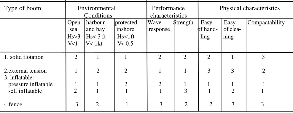
Finally, commercial booms may be grouped according to their basic types and
performance as well as their physical characteristics as shown in Table1.
Table 1- Types of boom, performance and physical characteristics
Source: manual on oil pollution
Hs = significant wave height
V= velocity of surface current
1= good; 2 = fair; 3 = poor
Type of boom Environmental Performance Physical characteristics Conditions characteristics
Open harbour protected Wave Strength Easy Easy Compactability
sea and bay inshore response of hand- of
Hs>3 Hs< 3 ft Hs<1ft ling ning V<1 V< 1kt V<0.5
1. solid flotation 2 1 1 2 2 2 1 3
2.external tension 1 2 2 1 1 3 3 2 3. inflatable:
pressure inflatable 1 1 2 2 1 1 1 1 self inflatable 2 1 1 1 3 1 2 1
3.2.1.1. Solid flotation boom
A solid floating material, for instance, plastic foam with cylindrical or rectangular form
secures the flotation of a boom. As part of the boom below the floating element is an
oil and water-resistant skirt with ballast along its lower side. To facilitate the use of
these kinds of booms they are usually supplied with a length not more then 20 meters
that can be linked by connectors.
The solid flotation booms have two major advantages. First, they do not need inflating.
Secondly, their buoyancy can not be affected by simple damage. As a disadvantage it
can be pointed out that they need a large storage capacity.
3.2.1.2. Inflatable boom
For inflatable booms the used floating element is an air chamber or tubes. The air is
supplied by an external system before the boom is deployed into the sea. However,
there are other types of inflatable booms with internal springs and no-return valves that
enable the self-inflation of the boom.
Inflatable booms have good wave characteristics and do not require a very large space
for storage. Their disadvantages are that they take a long time to deploy because they
need to be supplied with air unless self-inflatable. In addition, small damages on the
chamber can affect the buoyancy of the boom.
3.2.1.2. Fence booms
A single sheet comprises a fence boom, which serves as a freeboard and skirt; flotation
elements are attached almost in the middle and the ballast weights at the lower part of
The fence boom’s main advantage is that it does not require auxiliary equipment to
supply with air since the floaters are solid. Its major disadvantage is that due to the
wind and current effects its long span tends to lie over.
3.2.1.3. Bubble barriers.
A bubble barrier consists on a perforated pipe laid on the sea bottom. If air is pumped
into the pipe a screen of air bubbles rise and generate a counter-current on the sea
surface, which flows in both directions away from the bubble stream and holds oil
against a water flow up to 0.7 knots. Its main advantage is that it does not obstruct
navigation in the area for this reason can be used without problems in ports and
elsewhere in shallow water areas. Disadvantages include less effectiveness in deep
water and strong currents.
3.2.1.4. Sorbent booms
Sorbent booms are made of material with a high capacity of sorption. They can be used
for retaining or absorbing the oil. Because they are not very resistant, therefore, they
can not be towed, and can thus only be used in static work for retaining and collecting
oil in the case of small spills. Sorbent booms can be used in sections of different
lengths. Different to other booms, they are very light and can easily be transported.
They can only be used one time and their treatment and destruction requires a lot of
exercise.
3.2.1.5. Improvised boom
When a spill happens in remote area where is difficult to have the necessary quantities
of booms to contain the oil, booms may be made using indigenous available material
hoses and rubber tyres can be useful for the construction of improvised floating booms.
Beaches and sensitive coastal areas can be protected using sand barriers and stones.
3.2.2. Common boom failure during operation 3.2.2.1. Submergence Failure of the booms
Submergence failure is the situation when the boom is pulled below the water surface.
This occurs when the towing speed is too high. Normally it happens while positioning
the boom in the right configuration before the actual oil containment takes place. If the
boom already has contained some oil, entrainment failure will always occur before the
submergence failure. This can be corrected reducing the towing speed of the boom,
using a buoyancy ratio of 10:1 or higher. During transportation of a boom to the oil
spill area it should be pulled by only one vessel in a long tow, thus minimising the
forces on the boom.
Fig 1 submergence failure of the boom
3.2.2.2. Splash-over failure
Splash-over means that some of the contained oil passes over the freeboard of the oil
boom. It occurs when waves are choppy, i.e. the wavelength in relation to wave height
is lower than 5:1. This is often seen in shallow water. The risk of splash over can be
influenced by the construction of the boom due to the lower freeboard and a low
Splash-over can be overcome byusing sorbent booms as breakwaters upstream from the
boom formation, using a boom with a high buoyancy ratio in choppy and high waves.
Fig. 2 splash over failure boom
3.2.2.3. Drainage failure
Drainage failure is the situation when the oil contained in boom configuration escapes
under the skirt of the boom. Due to the current, when a large quantity of oil is
contained by the boom the skirt can not withstand the forces and the oil will begin to
escape beneath the skirt. This phenomenon can be reduced by placing a skimmer in the
drainage area, decreasing the relative speed of the boom; the depth of the skirt must not
exceed 1/3 of the water depth.
3.2.2.4.Entrainment failure
Entrainment failure is a situation when oil drops break away from the oil slick bottom,
which is enclosed within the containment boom configuration, and resurface outside
the boom configuration. It is also known as (sweep away or tear away). Normally, the
oil will flow with the same speed as the current and will be affected by the wave
velocity. It is impossible to avoid entrainment failure, in order to minimise the
entrainment problem; the velocity of the oil perpendicular to the boom wall has to be
lowered. This can be done in open water by lowering the boom velocity in relation to
the current. With fixed installation, often used in rivers, the only way to minimise the
problem is to deploy the boom in an angle to the current; this will result in reducing the
current speed perpendicular to the boom wall and prevent oil from being stopped by the
boom, otherwise the boom into the area with lower velocity will deflect the oil.
Fig 4 entrainment failure boom
3.2.3. Deployment of booms
Normally, the deployment of the boom takes place over the stern of the vessel. A
tugboat has a good open main deck, which is very suitable for deployment of
containment booms.
The equipment will often be used on board a vessel not designed for this purpose, or
attach the towing equipment, deploy the boom in sections, ensuring that the boom is
secured to the deck and connect the boom to the auxiliary vessel.
3.2.3.1. Standard boom configuration for open sea operations.
The basic purpose of deploying oil booms is to contain the oil, which is concentrated in
the apex of the boom. Boom configurations will depend on the number of vessels
involved in the operation. Typical configurations are:
1. Single vessel configuration with:
- Single sweep
- Dual sweep
2. Two vessel configuration
3. Three vessel configuration
In all these configurations, different formation are used like the V-formation in (single
sweep/dual sweep), J-formation in two vessel operations and U/open U-formation in
three vessel operations. Basically deployment and recovery of containment booms are
performed in the same way.
3.2.3.2. Standard boom configurations near shore and in rivers
A containment boom is often deployed near the shore in order to deflect the oil from
sensitive areas. Performing a successful operation requires familiarity with:
1. The prevailing environmental conditions, especially current direction and velocity, in
order to be able to determine the correct deployment angle.
2. The skit depth of the boom under water depth which, often is low in such areas. The
skirt depth should not exceed 1/3 of the water depth.
3. The tidal level differences, especially when e.g. an entrance to a harbour has to be
To compensate for tidal levels, it is an advantage to use a guide roller to secure the oil
tightness of the boom configuration during the change in tidal levels.
In near shore areas and rivers it is vital to have deployment points as well as anchoring
points prepared in advance. The boom deployment angle has to be determined to
ensure successful oil containment. In areas of fast current several skimmers should be
deployed. The areas with calm waters create optimal conditions for the skimmers. It is
important to prevent debris from reaching the booms.
3.3. Recovery equipment
Once the oil is contained, there is a need of quick recovery so it can not flow out and
reach safe areas. For this purpose a range and diversified amount of equipment has
been developed including skimmers, pumps, sorbents, vacuum trucks and others. Each
piece of equipment is used in certain conditions; some at the shore, others offshore.
3.3.1. Skimmers
There are different kinds of skimmers, either in size or in their way of work. However,
all of them are contain almost of an oil recovery, floatation or support arrangement and
pump. Self-propelled skimmers are quiet complicated since they can incorporate more
than one recovery element, a storage tank and some times may have an oil- water
separation facility.
According to the way they pick up the oil, skimmers can be divided into two groups:
suction and adhesion. The skimmers using the suction approach are fitted with a pump
or air suction system, which enables them to pick up the oil from the sea surface. The
main problem with that kind of skimmer is that it collects a large quantity of water. It is
Contrary to skimmers using the suction approach, skimmers, which adhesion is their
basic approach such as oleophic belt, discs, or synthetic rope do not collect large
volumes of water. The disadvantage of the skimmer with the adhesion approach is
related with viscous water-in-oil emulsion, which can be non-adhesive. In addition, oil
with low viscosity, for example diesel, does not accumulate on the oleophic surface.
To increase the efficiency of skimmers, a new generation has been designed which can
be permanently fixed on board ship with the possibility to carry out a long operation at
the sea. These vessel skimmers can act independently because they have sufficient
storage capacity. Vessel skimmers have been designed in different versions namely, a
sweeping arms, a combination of barriers and skimmers and scissors ship.
In all cases, skimmers work perfectly in good sea conditions and are likely to be
affected by rough sea. Oil weathering and sewage gathering affects mostly the
conventional skimmers. Also, as problems in operating with conventional skimmers it
can be mentioned the fact that they need an external power supply.
Most skimmers have a range of viscosity in which they can work best, though there are
no hard and fast rules, and they can be grouped according to the viscosity in which they
are most effective. A generalised grouping by performance according to oil viscosity is
shown below.
a) Light oil
Weir skimmer
Suction skimmer
Submersion belt skimmer
b) Medium oil
Disc skimmer
Drum skimmer
Rope mop skimmer
Floating head belt skimmer
Sorbent lifting belt skimmer
Sorbent submersion belt skimmer
Submersion belt skimmer
Drum-brush, chain brush skimmers
Submersion plane skimmer
Boom-skimmer
Vorlex skimmer
c) Heavy oil
Padle belt skimmer
Sorbent lifting belt skimmer
Rope mope skimmer
Drum-brush, chain brush skimmers
Weir skimmer with progressive cavity pump
Oil head weir skimmer
Waves and currents affect the performance of skimmers significantly. Waves affect
performance because rough seas move the skimmer's collection mechanism away from
the oil floating on the water surface, while the currents affect the performance of
skimmers because they cause the oil to escape under the collection booms. Also, high
currents may swamp intakes or cause surface oil to move and pass the collection
There are three performance parameters by which a skimmer can be tested. The first
parameter is Recovery Efficiency (RE), measured as the percent of oil in the recovery mixture. The second parameter is Throughput Efficiency (TE), which represents the ratio of oil recovered to oil encountered, expressed as a percent. Finally, the Oil Recovery Rate (ORR), the rate at which pure oil is being recovered in litters per minute (LPM) and cubic meters per hour (m3/h).
3.3.2. Sorbents
The recovery of oil using sorbents is based on adsorption or absorption properties of
certain materials. This has to be seen strategically as an alternative or auxiliary
response operation; at the same time it can be taken as a principal response option in
the case of small spills. The kind of sorbent to be used will depend upon availability
and its performance. However, it has to have acceptable characteristics namely, high
absorption efficiency, easy recovery after absorption and easy processing after
recovery.
According to the material make up the sorbents can be divided into three main groups;
firstly, natural organic material, such as cotton, pine bark peat and pulp; secondly,
mineral- based material namely, volcanic ash, perlit and vermiculite.
In all cases the use of sorbents must observe three phases. The first stage is distribution
of the sorbent, followed by collection ending with disposal. The disposal process is of
great importance since the sorbents are mixed with oil and need to be stored in a place
3.4. Use of dispersants
Along with the development of the containment and recovery equipment another
methods of combating oil spills have been developed. These combating methods are
based on the use of dispersants and relay on the characteristics of molecules of certain
substances to be able to develop affinity with oil and water at the same time. The
affinity for oil is known as oleophile and the affinity for water is known as hydrophile.
The application of dispersants on the sea surface covered by oil enables the reduction
of tension between the two liquids and creates the appropriate condition for formation
of very small droplets which disperse in an area relatively bigger than the previous. In
fact dispersants do not remove the oil from the sea but divide it into small particles
enabling it to disperse through the water column.
The efficiency of the dispersant depends on many factors. First, the viscosity of the oil,
normally oil with very high viscosity does not react satisfactorily to the application of
dispersants. Second, weathered oil up to a state of viscosity greater than 2000 cSt
resists the effect of dispersants. Furthermore, special additives in lubricating oil
influence badly the effectiveness of the dispersants. Finally, after a long time of oil
exposure the dispersant may not be effective.
3.4.1. Types of Dispersnts
There are two types of dispersants available today, namely, hydrocarbon and
concentrate dispersants. Hydrocarbon or conventional dispersants as they are known,
rely on hydrocarbon solvents. Dilution with seawater before application reduces their
effectiveness. The second type dispersants, concentrate or self-mixed are a mixture of
emulsifiers, solvents and wetting agents, containing very active elements capable of
4.4.2. Application of Dispersants
Dispersants can be sprayed using a vessel or an aeroplane. In both cases special
equipment must be installed on board. The vessel or aircraft to be used can be selected
depending on the size of the spill. However, when the vessel is to be used there always
will be a need to use an aircraft to facilitate the location of the slick once the oil has
drifted away from the source.
With the lack of appropriate equipment, the fire fidgeting equipment can be improvised
for the purpose, although, not in the case of using hydrocarbon solvent dispersants
knowing that their pre-dilution affects their effectiveness.
The use of an aircraft is much better than vessel spraying, because is rapid and provide
an effective surveillance. However, weather conditions can limit the possibility of
aircraft use. The appropriate dispersants to be used in aircraft spraying are the
concentrate dispersants because they do not need the additional mixing of the wave
effect.
3.4.3. Environmental problems
The use of the dispersants has been a subject of discussion, due to the fact that some of
the substances are toxic and are not considered environmentally friendly. Furthermore,
the fact that dispersants do not remove the oil from the sea, but break it into small
droplets and allow the oil to disperse in a larger area, raises the concern because of the
eventual threat to the biota. Next, dispersants by themselves are nutrients, this means
that their use represents an addition to the nutrients in the sea, which is not permissible
in close waters, knowing that it can contribute to eutrofication. Bearing in mind all
these, problems each country has its policy related to the use of dispersants. Some use
dispersants as the principal method for oil spill combating, others use them as an
on the use of dispersants, the risk of environmental damage resulting from their use
must be balanced against the probable effects of the untreated oil. Dilution potential
will be an important consideration. The policy for dispersants use should be agreed in
advance for each area and in all cases the use of dispersants must be co-ordinated with
Chapter IV
Clean-up Strategy and Clean-up Techniques
4.1. Clean-up strategy
At the outset of the oil spill, a strategical decision is made on whether to respond or
not, and the techniques and technologies that will be employed. However, to some
extent these decisions might be pre-designed and agreed in the contingency planning
process. Depending on the geographical area, size of spill, environmental and economic
resources endangered, options are limited and focused on in the beginning. Thus, a
definition of a clean-up policy, mapping of shoreline and, preparation of a decision
guide should be part of the clean-up strategy, which should be clearly indicated in the
CP, particularly in the clean up policy, in order to facilitate a quick decision response.
The strategic decision making process necessarily needs a good comprehension of
technologies and operational constraints of various countermeasures and clean-up
techniques. Any anticipated environmental effect and policy constraints that may
apply, for instance, the use of dispersants and in-situ burning in some areas should be
included in the contingency plan.
4.1.1. Assessment of the problem.
Along with clean-up the strategy, the assessment of the problem gives a real picture of
the situation on the ground and helps to find the real solution. As soon as the oil spill is
identified or reported the very first step to be taken is to determine the quantity of oil
and identify the source. In addition, determining the possible area and the type of the
surveillance, the use of boat to have access to the close areas and a survey of the
shoreline on foot or by car.
The assessment, in the first moment of the emergency should be used to decide the
strategy to follow between possible options. For instance, in some countries the use of
dispersants depends on the conditions on a case by case basis.
In order to minimise the debate over the most appropriate response option it is very
important to involve all interested groups from the beginning. However, the
assessment of oil impact must be done at the time permitted or with a specific written
waiver obtained in advance to avoid any waste of time in discussion.
4.2. Clean-up techniques.
The purpose of clean-up techniques is to offer an overview of various techniques
developed through the years based on experience the of previous oil spill combating
operations. The currently used response techniques include booming, which is the use
of physical barriers to contain oil for removal; exclude and divert it from sensitive
areas. In diversion booming, the boom is deployed at an angle to the approaching slick.
The oil is diverted away from sensitive areas for recovery. This is used on inland
streams where currents are greater than 1 knot, across small bays, harbour entrances,
inlets, rivers or creek mouths where currents exceed 1knot and breaking waves are less
than 1.5 feet; and on straight coastline areas to protect specific sites.
The environmental effect of diversion booming is characterised by minor disturbances
to the substrate at the shoreline anchor point; the diverted oil can heavily contaminate
In exclusion booming, the boom is deployed across or around sensitive areas and
anchored in place. The approaching oil is deflected or contained by the boom. Its
primary use is across small bays, harbour entrances, inlets, river or creek mouth where
currents are less than 1 knot and waves are less than 1.5feet in height. Its
environmental effect is linked with minor disturbances to the substrate at shoreline
anchoring points.
Chemical treating agents, which involves the application of chemicals to accelerate the
dispersion of on oil spill into the water column, wash it from the shoreline, herd it into
a small area, or modify it to facilitate its removal. Its environmental effects are the
same as the dispersants effects. In dispersants the active ingredients are surface-active
agents or surfactants. These surfactants have varying solubility in water and have
varying actions toward oil and water. A parameter that has been used to characterise
surfactants is the hydrophillic-lipophilic balance (HLB). A surfactant with an HLB of
about 1 to 8 promotes the formation of water-in-oil emulsion and one with an HLB in
the range from 12 to 20 promotes formation of oil-in-water emulsions.
Dispersants have usually HLB's in the range of 9 to 11. The HLB as defined is only
applicable to non-ionic surfactants, however, ionic surfactants can be rated using an
expanded scale and often have HLB ranging of 25 to 40. They are strong oil-in-water
emulsifiers, very soluble in water, relatively insoluble in oil, and generally work from
the water to any oil present. Such products have little application to oil-in-water
because they rapidly disappear in the water column, having little effect in oil.
In-situ burning involves the burning of the oil on the sea surface, or in some cases on
the shoreline. The oil can be ignited with a high degree of efficiency if the oil slick is:
q Of adequate thickness
q Not too much emulsified
The following equipment and trained personnel are necessary for in-situ burning.
q A fireproof boom with about 500 feet length
q Two sections of a conventional boom that can be attached to the fireproof boom
q Two towing vessels capable of towing the assembled boom at 0.7 knots and having
at least 500 feet of towline each
q A heli-torch suspended from the helicopter
q Clean-up crew with appropriate equipment
q A boat to collect residues
The primary advantages of the in-situ burning technique are, first of all, a large quantity
of oil can be removed rapidly and efficiently (typically 80%/90%) (A. A. Allen 1991).
Secondly, virtually any type of oil can be burnt. Next, oil can be safely and effectively
eliminated without the need for recovery, transfer, store and disposal. Furthermore,
in-situ burning can be conducted with a minimal amount of logistics and personal support.
Finally, it is possible to undertake an in-situ burning operation under a broad range of
environmental conditions. It may be the only practical response technique in areas
which are partially covered with ice or in shallow water situation.
The disadvantages of in-situ burning are related to the environmental and operational
concerns and include, first, a generation of black smoke. Second, it involves the usual
safety risks that accompany any large petroleum fire, such as high temperatures and
reduction of visibility. Finally, the surface between the seawater and oil will be heated.
However, this area is small compared to the total surface area.
Mechanical removal involves physically removing the oil from the sea surface using
Shoreline clean up includes a wide range of techniques to remove oil and oiled
materials from the shoreline.
3.2.1. Bioremediation.
Boiremediatiom is the application of nutrients and in some cases jointly with bacteria
(fertiliser containing nitrogen and phosphate) to the shoreline to accelerate the natural
biodegradation of oil. Oil biodegradation is the natural process by which
micro-organisms oxide hydrocarbons, ultimately converting them to carbon dioxide. It can
only take place at an oil-water interface. It is limited by the availability of oxygen,
moisture, and nitrogen/phosphorus nutrients needed by microbes. Bioremediation is
typically used as a final treatment step after completing conventional shoreline
treatment, or in location were other forms of treatment are either not possible or not
recommended.
4.3. Disposal of Oil and Debris
The type and quantities of wastes resulting from oil spill cleanup are the very important
factors in the disposal of wastes. These factors depend mostly on the cleanup methods
used and are the subject of change as the work is progressing. Thus a management
program to deal with oil and debris must be set up based on following the principles:
q Provide safe working conditions and necessary personnel protection.
q Comply with the applicable laws and regulations
q Minimise future liability
q Co-operate with local community and environmental agencies to minimise impact
on local waste disposal facilities.
q Handle, store and transport the oil waste in appropriate containers/tanks.
q Minimise the amount of waste generated by implementing waste reduction
q Segregate oily wastes and non-oily wastes to allow optimum reclamation and
disposal of each waste stream.
q Dispose of all waste streams in a safe way an at approved disposal sites.
Plans for handling and temporary storage of wastes during the initial stages of oil of an
oil spill response should be discussed with the regulatory agencies involved. If there is
any doubt, specialists should be consulted.
Since each type of waste has a different optimal or alternate disposal method it is
important to:
q Segregate wastes by type
q Minimise the quantity of each type
q Avoid mixing hazardous and non-hazardous wastes together, resulting in a large
volume of hazardous waste
q Label all waste containers and identify the source.
One way to improve the efficiency is to combine similar wastes and segregate
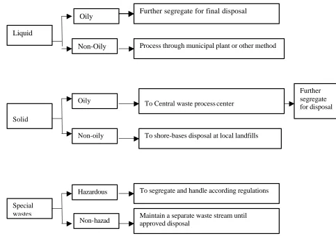
Fig 5 chart for waste separation
Segregation of wastes at the point of generation should be done to facilitate subsequent
handling and disposal.
q All oily wastes should be segregated from non-oily wastes
q Non-oily wastes (domestic refuse and trash) should be transported to shore-bases
for disposal at local landfills.
q All oily solid wastes should be transported to a central waste processing area.
Liquid
Solid
Special wastes
Oily
Non-Oily
Oily
Non-oily
Hazardous
Non-hazad
Further segregate for final disposal
Process through municipal plant or other method
To Central waste process center
To shore-bases disposal at local landfills
Further segregate for disposal
To segregate and handle according regulations