INTRODUCTION
In recent years, the existing energy sources have been studied by energy politicians, compel-ling a search for new energy sources including the wind. Although there are large wind farms currently working to produce power in national grids, anoth-er field regarding the enanoth-ergy of wind is also emanoth-erg- emerg-ing. Autonomous wind turbines are new trends in the power production for distant spots or separate sites in which connection to the grid is very ex-pensive or even impossible. Multivariable control systems can also be used to adjust the power of the generator and minimize the load on the rotor blades in high wind speeds [1]. Reversible integration in grids can be faced with the problems connected with the disruption abilities in the grid. These problems might be power quality, frequency or voltage functions [2]. Using compliance
control-lers with the presence of unbalanced loads which are subject to sudden changes, guarantees the stability of the three-phase source [3]. In autono-mous wind turbines, the turbine system should be ready for any situation. These situations usually depend on the employed control strategies. Even the disruptions of different power qualities can be identified and eliminated using wavelet trans-formation analysis [4]. The empirical results in [5] imply that the experiment can be effective on a separate load in the real time of the behavior of a wind energy conversion system (WECS) by a digital signal processing (DSP) model. In the field of renewable energies, three aspects of wind energy were investigated: the status, the poten-tials and the evaluation and analysis policies [6]. In order to improve the adjustment of the DC-bus voltage significantly, the SC storage was performed regarding load conditions and wind
Volume 13, Issue 4, December 2019, pages 60–69
https://doi.org/10.12913/22998624/111706
Designing and Modeling of Control Strategies Based on
Multi-Objective Optimization for a PMSG Wind Turbine:
A Study Based on the Grid Errors and Wind Speed
Ehsan Ganji
1*, Mehdi Mahdavian
2, Iman Eshaghpour
3, Mojtaba Janghorban
11 Acecr Institute of Higher Education, Kermanshah, Iran
2 Department of Electrical Engineering, Naein Branch, Islamic Azad University, Naein, Esfahan, Iran 3 Department of Electrical Engineering, Kashan Branch, Islamic Azad University, Kashan, Iran * Corresponding author’s e-mail: [email protected]
ABSTRACT
In this paper, an independent wind energy conversion system was studied with the control strategies used to
pro-vide power specifically to the areas far from the grid. In this research, three strategies are designed and used in order to stabilize the output. This system contains a directed rectifier which is responsible for maximum power point tracking. Additionally, a common DC bus and a fully controlled inverter were designed. An LC filter was
also used in the system in order to eliminate switching harmonics to a considerable extent and provide a reliable noiseless source for load supply. Since the power demand and the produced power of the turbine are variable and indistinguishable in each moment, a depletion load is also placed in the system. In this study, it was observed that
the designed strategies prove the output stability in different sections and under different conditions with resona -tors and non-linear PI and PID controllers. The designed strategies were also supported by the simulation results.
Keywords: wind turbine, permanent-magnet synchronous generator (PMSG), output stability of the turbine, resis-tive depletion load, voltage damping, Reduction of switching harmonics.
Research Journal
Accepted: 2019.11.16speed fluctuations using a buck-boost converter. Moreover, the stability of the three-phase voltage source of the energy system, the DC-link power and the voltage control were studied line by line [7]. A multipurpose system was designed in a wind turbine emulator (WTE) to develop and examine new control strategies for wind energy conversion systems. This multipurpose system was designed using a processing module to control a separate DC motor. The core of the processing module of the DSP system is used for a structure that easily provides the changes of wind speed and turbine parameters and supervision over system variables [8]. The classic control of the slow dynamics with respect to the mechanical dynamics of the drive is a new solution in commercial wind turbines, which proves that a dynamic control can help speed up the adjustment and observe a significant compari-son in the aerodynamic efficiency with a normal control process. Basically and in theory, dynamics control is better than non-classic control, which leads to higher efficiency and reliability [9]. The mechanical tensions in the turbine are improved based on the repair and maintenance demands and the average time between failures. In order to achieve these goals, the signal of the control loop without a speed sensor can be adequately con-trolled in a reference speed using a constant-slope ramp signal and a certain algorithm [10]. Under the condition of wind speed imbalance, the turbine can be adequately controlled without any tensions or problems by designing nonlinear and dynamic rotor field and flux controllers and a wind turbine speed controller using sliding mode techniques, the fuzzy logic, maximum power point tracking and the uncertainty state [11].
An energy storage system (ESS) installed on a power system can effectively control the oscillations of the power system with active power or the ESS reaction in power systems [12]. Maximum power point tracking (MPPT) can ensure the reliability of the output power of the system completely by extracting the maximum power from the wind turbine us-ing the search algorithms and by controllus-ing the DC-DC converter in the PWM and in the DC-AC converter under the condition of wind speed imbalance [13]. The grid-side converter is constantly working to control the supply and production of electric power and prevent the supply of harmonics and the reactive power by the nonlinear load in the PCC [14]. The pulse width modulation (PWM) [15, 16] is used by
dis-turbance rejection and the optimization of the dynamic performance of the motor drive using IMC [23]. A VFC can meet the demands of the reactive power of an asynchronous generator along with load leveling, harmonic elimination, voltage adjustment and load balancing [24].
By comparing the response of control systems with ADRC controllers, many researchers believe that control engineering might be ready to break into the new generation of controllers from the classic PID controller [25]. There is no need for the complete details of the system model to de-sign a nonlinear adaptive controller (NAC), since this area is capable of adaptation and resistance to the uncertainty of system parameters, system dynamics and external disturbances [26].
THE DESCRIPTION OF THE STUDIED
CONTEXT AND CONTROL STRATEGIES
The turbine model
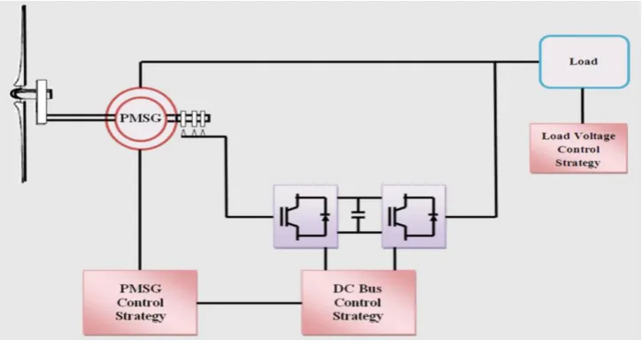
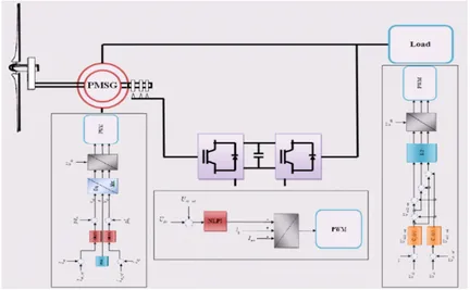
The context studied to evaluate the perfor-mance of a 2 megawatt autonomous wind turbine was simulated with the use of a PMSG which was coaxially connected to a back-to-back converter. This system also contained a directed rectifier which is responsible for maximum power point tracking, a common DC bus and a directed power inverter. Following the inverter, an LC filter was placed in the system to attenuate all switching harmonics while working and to provide a noise-less sinusoidal voltage source for the three-phase Nomenclature
Vw wind speed, m-1 Ps, Qs active and ractive statoric powers / W (var)
ρ air density, kg m-1 Tem PMSG torque, N m
R blade radius d, q synchronous reference frame index
λ tip-speed ratio It1, It2, It3 inverter output currents
Cp power coefficients IL1, IL2, IL3 load currents
Pa aerodynamic power, W RL1, RL2, RL3 load resistances
Ta aerodynamic torque, N m LL1, LL2, LL3 load inductances
Ωt aeroturbine rotor speed, rad s-1 Udc DC bus voltage
Ωm generator speed, rad s-1 Iinv inverter input current
Ωs synchronous generator speed, rad s-1 Rs, Rr stator and rotor Resistances, X
Ct filter capacitance Ls, Lr stator and rotor Inductances, H
J turbine total inertia, kg m2 Lm mutual inductance, H
G gearbox ratio Uc1, Uc2 line - to - line voltages
ωs synchronous speed, rad/s Um1, Um2 inverter voltages
load supply. Since the load power demand was variable and the amount of power produced by the turbine was unpredictable, a depletion load was used through a chopper in the DC-bus strat-egy. In the case of mass production, the excess energy is directed to the depletion load. This is the case we have studied in our experiments.
The aerodynamic power anticipated for the wind turbine is as follows [11].
Pa = 0.5ρπR2Vw3CP(λ, β) (1)
In the equation above, CP is the coefficient of a
nonlinear function which is given in the following:
CP (λ) = a0 + a1λ + a2λ2 + a
3λ3 + a4λ4 + a5λ5 (2)
In which:
(3)
That
(4)
A simple and practical model for the air flow rate is given in the following based on [11].
(5)
Figure 1 illustrates the complete structure of the proposed system. In the following chapter, the con-trol strategies will be discussed according to table 1.
The PMSG control strategy
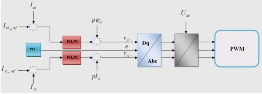
The control strategy for the PMSG section is formed around the regulatory ring using Isd and Isq in the d-q component.
A first-order Park transform is used to write the equations for the Ia, Ib and Ic currents. Two
designs for nonlinear PI controllers are used here in order to provide the equations of the stator
currents by taking into account the values of the reference currents Isd-ref and Isq-ref. In the
fol-lowing, the vector control strategy describes the required equations for the reference currents of the PMSG:
(6)
In which Tem_PMSG_ref is the reference
elec-tromagnetic torque of the PMSG. This torque should have the following form in order to ensure the stability of the MPPT system in the PMSG:
(7)
After writing the stator current equations, the stator voltages Vsd and Vsq for the proposed
sys-tem are calculated in the Park reference frame as follows:
(8)
(9)
In this design, the values and equations of the three-phase voltages Va, Vb and Vc can be
ob-tained through the equations of the inverse Park transform. Afterwards, the working periods are determined for different cases in order to produce three signals to control the rectifier in the PWM.
The nonlinear control of the blade pitch
First, we consider the definitions and the con-ditions of continuity for wind disturbances:
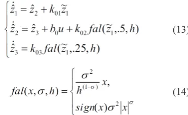
We define z1 = x1, z2 = ̇ x1 and z3 = ψ(x,z); thus, we obtain the following equations:
(10)
Considering ͠z1 = z1 - ẑ1, we obtain a linear
ESPO:
(11)
Considering ẑ1(i = 1, 2, 3) and ͠z1, an error is
obtained for z1. If k0i is the parameter coefficient: (12)
In which α0 is the bandwidth observer of the
only parameter being adjusted.
Thus, the wind speed of a nonlinear ESPO system can be estimated according to the follow-ing equations:
(13)
(14)
In which x is the input error, σ is the index accuracy in the 0-1 range and h is the width of the linear part of the nonlinear function.
Using the obtained equations and the results of the ψ ^(x) disturbances and the third-order ESPO, the U input control is written in the following:
(15)
x1 is given in the following, considering
the difference between the rotor speed and the reference speed:
(16)
Finally, the nonlinear control of the control pitch is described as below:
(17)
The schematics of the nonlinear PI (N-PI) control system of the blade angle are illustrated in the figure above. By applying the results from table 1, this system was designed by considering several purposeful plans in order to compensate for all the disruptions and shortcomings of non-linear controllers.
The DC-bus control strategy
In the dynamic and control discussions of modeling studies, using a DC-bus in the struc-ture of VSWTs provides the possibility of plac-ing an ESS system which plays a role in the quality improvement of the power produced in all the collections at the time of disruption, in addition to the stability of the system. The DC-bus control strategy leads to the balance between the two sides of the system stability and gener-ally depends on the balance between the compo-nents and energy production. Due to the uncer-tainty and the dependency of the production on weather conditions, a control system for the ESS was also designed and simulated.
When the wind speed is high and excessive production occurs in the system, the depletion load in wind turbines is connected to the DC-bus using a chopper, eliminating the effects of the excess power in the system. The PWM signal that controls this chopper is obtained by the nonlinear PI controller. This signal causes the DC-bus control to remain in the constant voltage which is intended for the system (400 Table 1. The nonlinear controller and the FNLC parameters
Parameters Value
FLC/N-PI Proportional gain (1/s2) 6.3
FLC/N-PI Integral gain (1/s), ki 0.26
ESPO equivalent input gain (°s3 /rad), b
0 0.04
ESPO nonlinear coefficient (rad/s), h 0.001
ESPO observer bandwidth, α0 40
ESPO estimation gain (1/s), k α1 1.2 × 10²
ESPO estimation gain (1/s2), k α2 4.8 × 10³
volts). Thus, we observed no changes in the out-put. However, in most systems, using an ESS leads to the conditions in which production can be fully controlled. Another solution for this case is the application of hybrid systems such as wind-diesel, wind-hydrogen and wind-pho-tovoltaic-hydrogen systems. We are planning to carry out this investigation in another article in the near future.
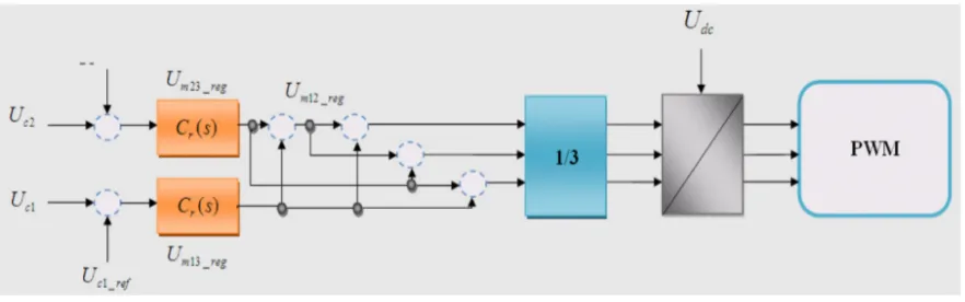
The load voltage control strategy
In power systems, the output voltage control strategy uses an RLC filter to control the output. The Uc1 and Uc2 elements are used for adjusting
and controlling the resonators. Using the control equation of Cr(s) in this design is appropriate for
adjusting the shape of periodic waves. The refer-ence voltages Uc1_ref and Uc2_ref are considered to have the following form:
Fig. 3. The proposed nonlinear PI controller (N-PI)
Fig. 4. An illustration of the DC-bus control
(18)
In which Un is called the rated voltage. Al-though the RLC filter follows a quadratic equa-tion according to equaequa-tion (9), it is given in the following form for resonance control:
(19)
In which d1, d0, c3, c2, c1 and c0 are the
pa-rameters of the resonance control section and ωp
is the angular frequency of the controller. The application of these elements is fully explained in reference [4].
In the system above, the outputs of the reso-nance system which are the three-phase control voltages (the Um13_reg and Um23_reg elements) are given in the following:
(20)
THE SIMULATION RESULTS
This experiment has been conducted for a time period of 30 seconds. First, the wind blew
on the turbine blades based on an unbalanced equation graph. Some diagrams were obtained from the turbine experiment in order to confirm the accuracy of its performance. The remaining time was spent on the changes of the three-phase load. The temporal procedure in different cases and the results simulated by MATLAB Simulink are given in the below.
The temporal procedure in different cases:
• 0 to 5 seconds, no load
• 5 to 9 seconds, resistive load added
• 9 to 14 seconds, inductive load added
• 14 to 18 seconds, resistive load reduced
• 18 to 23 seconds, load imbalance occurs
• 23 to 30 seconds, induction load fully removed. Figure 7 illustrates the speed of the wind that blows on the wind turbine. It is evident that the imbalance of the wind speed occurs after 5 sec-onds. Figure 8 shows the performance of the non-linear control system of the blade angle at the time of imbalance; in a way that the angle between the turbine blades is changed linearly in time to pre-vent any damage that might be caused by the wind speed. The reaction of the system to the imbalance was observed to be linear in this figure.
verter. While analyzing dynamic systems, the sys-tem efficiency is typically studied which determines whether or not the control systems have been suc-cessful in achieving the best efficiency for the out-put. Figure 10 plots the diagram of the power
qual-ity factor which shows the value 0.55. This value is significant in the control systems of a wind turbine.
Studying the results of the output power for the studied experiment in figure 11, we can clearly ob-serve the changes of the power value under different
Fig. 7. The wind speed
Fig. 8. Blade angle changes
Fig. 9. The DC-link voltage
Fig. 10. The power quality factor
Fig. 11. Power changes in the normal mode.
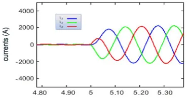
Fig. 12. Current changes under the studied conditions
Fig. 13. Current changes in a specific time period of
the experiment
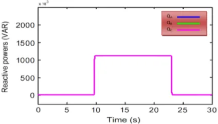
conditions. As can be seen, the value of the output power is fixed on 2 megawatts in the figure, which confirms the precise performance of the control sys-tems. Figure 12 illustrates the current changes in the system when the corresponding loads are added. These loads may or may not be balanced. This dia-gram shows a precise analysis of the system behav-ior. Moreover, figure 13 displays the behavior of the system currents under the studied conditions in a specific period of time. The stability of the output voltages adjusted under the studied conditions can easily be seen during the changes of the system cur-rents using the behavior of a compliance system in figure 14. The active and reactive powers used in the system during load changes are illustrated in figures 15 and 16. The active powers all follow a constant value at the time of the changes and the reactive powers react to the addition of the inductive loads.
CONCLUSIONS
In this paper, we studied a 2 megawatt au-tonomous PMSG wind turbine with balanced and unbalanced three-phase loads. The simulation results indicate that the proposed controllers pre-cisely resolved the problems caused by the imbal-ance of the wind speed, switching harmonics and the changes of the three-phase loads. These con-trollers maintain the stability of the system and produce a fully controlled power in the output.
While designing filters and compliance con-trollers for adjusting the output voltage, we can see that the efficiencies of the nonlinear control-lers and feedbacks in the system are very precise at the time of imbalance. They comply with the other components of the system and are complete-ly effective and practical for the control systems of the turbine. The compliance of the nonlinear
controllers in PMSG strategies and the control of the blade angle by tuning these controllers is also an effective method for the controllers to react to the imbalance in order to control and protect the turbine and stabilize the output.
The simulation results in this study are applica-ble to a suburban site by taking into account all en-vironmental factors. These results can guarantee the control of power supply for an isolated village which is not included in any power plant transmission line.
REFERENCES
1. Jackson G, Liu, Söffker D. Multivariable Control
of Large Variable-Speed Wind Turbines for Gener-ator Power Regulation and Load Reduction. IFAC-PapersOnLine Volume 48, Issue 1, 2015; 48(1), 544–549.
2. Kishor V, Ballal M S, Moharil R M. Investigation for Causes of Poor Power Quality in Grid Connect-ed Wind Energy - A Review. Power and Energy En-gineering Conference (APPEEC) 2012:34(1), 1–6. 3. Abdelkafi A, Masmoudi A, Krichen L. Experimen
-tal investigation on the performance of an autono-mous wind energy conversion system. Int J Electr Power Energy Syst 2013; 44(1), 581–90.
4. Bhadane K, Ballal M S, Moharil R M. Wavelet transform based power quality analysis of grid connected wind farm - An investigation of Power Quality Disturbances. Advances in Electrical En-gineering (ICAEE) International Conference on 2014; 84(8), 1–6.
5. Masmoudi A, Krichen L, Ouali A. Voltage control of a variable speed wind turbine connected to an isolated load: experimental study. Energy Convers Manage 2012; 59, 19–26.
6. Dincer F. The analysis on wind energy electricity generation status, potential and policies in the world. Renew Sust Energy Rev 2011; 15(9), 5135–42.
Fig. 15. The output active power under the studied
7. Masmoudi A, Abdelkafi A, Krichen L. Electric
power generation based on variable speed wind turbine under load disturbance. Energy 2011; 36(8), 5016–26.
8. Battaiotto PE, Mantz RJ, Puleston PF. A wind tur-bine emulator based on a dual DSP processor sys-tem. Contr Eng Pract 1996; 4(9), 1261–6.
9. Camblong H, Martinez de Alegria I, Rodriguez M, Abad G. Experimental evaluation of wind turbines maximum power point tracking controllers. En-ergy Convers Manage 2006; 47(18–19), 2846–58. 10. González LG, Figueres E, Garcerá G, Carranza O.
Maximum-power-point tracking with reduced me-chanical applied to wind-energy-conversionsys-tems. Appl Energy 2010; 87(7), 2304–12.
11. Ganji E, Mahdavian M. A Controlling Method of DFIG-Based Wind Turbine for Stability Improve-ment of Power Delivery to the Power Grid. Journal of Electrical Systems 2016:12(4), 591-611. 12. Du W, Wang HF, Cheng S, Wen JY. Robustness
of damping control implemented by energy stor-age systems installed in power systems. Int J Electr Power Energy 2011; 33(1):35–42.
13. Kesraoui M, Korichi N, Belkadi A. Maximum power point tracker of wind energy conversion sys-tem. Renew Energy 2011; 36(10), 2655–62. 14. Singh M, Khadkikar V, Chandra A. Grid
syn-chronisation with harmonics and reactive power compensation capability of a permanent magnet synchronous generator-based variable speed wind energy conversion system. IET Power Electron 2011; 4(1), 122–30.
15. Melício R, Mendes VMF, Catalão JPS. Power con-verter topologies for wind energy conversion systems: Integrated modeling, control strategy and performance simulation. Renew Energy 2010; 35(10), 2165–74. 16. Rodriguez J, Rivera M, Kolar JW, Wheeler PW.
A review of control and modulation methods for matrix converters. IEEE Trans Ind Electron 2012; 59(1), 58–70.
17. Zhong L, Rahman MF, Hu WY, Lim KW, Rahman MA. A direct torque controller for permanent mag-net synchronous motor drives. IEEE Trans Energy Convers 1999; 14(3), 637–42.
18. Holdsworth L, Wu XG, Ekanayake JB, Jenkins
N. Comparison of fixed speed and doubly-fed
induction wind turbines during power system disturbances. IET Power Electron 2003; 150(3), 343–52.
19. Li X, Su M, Sun Y, Dan H, Xiong W. Modulation strategies based on mathematical construction meth-od for matrix converter under unbalanced input volt-ages. IET Power Electron 2013; 6(3), 434–45. 20. Singh N, Agrawal V. A review on power quality
enhanced converter of permanent magnet synchro-nous wind generator. Int Rev Electr Eng (IREE) 2013; 8(6), 1681–93.
21. Chen Z, Spooner E. Voltage source inverters for high-power, variable-voltage DC power sources. IEEE Proc Gener Transm Distrib 2001; 148(5), 439–47.
22. Xia C, Zhao J, Yan Y, Shi T. A novel direct torque control of matrix converter-fed PMSM drives us-ing duty cycle control for torque ripple reduction. IEEE Trans Ind Electron 2014; 61(6), 2700–13. 23. Ponmani C, Rajaram M. Compensation strategy of
matrix converter fed induction motor drive under input voltage and load disturbances using inter-nal model control. Int J Electr Power Energy Syst 2013; 44(1), 43–51.
24. Singh B, Sharma S. SRF theory for voltage and fre-quency control of IAG based wind power generation. IEEE Int Conf Power Syst ICPS 2009, 2009:1–6. 25. Han J. From PID to active disturbance rejection
control. IEEE Transactions on Industrial Electron-ics 2009; 56(3), 900–906.