313
Copyright © 2011-15. Vandana Publications. All Rights Reserved.
Volume-5, Issue-3, June-2015
International Journal of Engineering and Management Research
Page Number: 313-320
Experimental Analysis of Heat Exchanger and Simulation of Result
using Solid Work
Ankit Kumar1, Ajay Kumar2 1
Scholar, Department of Mechanical Engineering, OITM Hisar, INDIA 2
Assitant Professor, Department of Mechanical Engineering, OITM Hisar, INDIA
ABSTRACT
Heat exchangers one of the most important heat and mass transfer apparatus in industries like electric power generation, oil refining and chemical engineering etc. are designed with preciseness for optimum performance and long service life. This paper analyses counter flow and parallel flow heat exchanger by experimentally and analytical by using solid works software. The paper also consist of experimental data of counter flow and parallel flow heat exchanger and simulate the over data on software using solid works. Simulation gives different flow of trajectory and flow of heat from hot and cold water. This method used in design of heat exchanger with a baffle cut of 25%. The result obtained in this paper shows us that the desired properties from a heat exchanger i.e overall heat transfer coefficient, shear stress, heat flux, and other factors which are helpful for the design of heat exchanger. In both results we find the difference between the experimental value and the analytical value of overall heat transfer coefficient value. The difference are found due to fouling factor, cavitations and design of heat exchanger.
Keywords— Counter flow and parallel flow heat exchanger, overall heat transfer coefficient, log mean temperature difference and solid works software.
I.
I
NTRODUCTIONHeat exchanger is nothing but a device which is used to transfer the heat from one medium to another medium. The heat transfer medium may be fluids, gases and other medium. Heat is exchange between two fluids due to temperature difference. Heat exchangers are used in various filed such as industry, power plant, nuclear reactor, in domestic. Heat exchanger is used in space heating, air-conditioning, waste heat recovery and chemical processing. In heat exchanger heat is transfer due to convection process on the each side of fluid and the conduction through the wall of the heat exchanger which is separates the fluid. Therefore, we have to analysis of overall heat transfer coefficient and logarithmic mean temperature
difference. Heat exchanger is also help to find the effectiveness of the device. A typical or best example of a heat exchanger is found in the internal combustion engine. In which hot fluid is circulating through the radiator and the air flows pass through the coils. This cools the coolant and the heat is transfer in the incoming air. For better efficiency heat exchanger are designed to maximize the surface area of the wall between the two fluids and minimize resistance to the fluid flow through the heat exchanger. The exchanger’s performance can also be affected by the addition of fins in both directions. Which increase the surface area and the increase the fluid flow and decrease turbulence. And the temperature across the heat transfer varies with position, and it can be find with mean temperature.
There are various type of heat exchanger which are used at according to requirement. According to heat transfer process:
1. Direct contact type: In this two different fluids are used to transfer the heat from each other. This type of heat exchanger are used in cooling tower, jet condensers, feed water heater.
2. Storage type heat exchanger: In this type of heat exchanger fluids are flows alternatively at a time. When the hot fluid first flow through the heat exchanger, it transfer the towards the wall of the heat exchanger and after some time cold fluid are flow through the same tube of heat exchanger there after hot walls losses their heat towards cold fluid.
According to construction, heat exchangers are divided into:
3. Tubular heat exchanger: This type of heat exchanger containing the two tube which are concentric into each other. This type of heat exchangers work on the convection and conduction process. These types of heat exchanger have many sizes and shapes and have different flow arrangement.
314
Copyright © 2011-15. Vandana Publications. All Rights Reserved.
industry. This type of heat exchangers also known as surface condenser. This type of heat exchanger used for heating, cooling, condensation and evaporating application. These types of heat exchanger are consisting of a shell and large number of tubes. These tubes are arranged in parallel to each other. The heat transfer takes place as one fluid flow through the tubes and other fluid flow through the outside of the tubes through the shell. In this baffles are created to turbulence and to maintain the equal spacing between the tubes and it also help for the large the heat transfer rate. They have large surface area in small volume.
5. Plate heat exchanger: This is another type of heat exchanger. This type of heat exchanger consists of composed of multiple, thin and slightly separated plates. They have lager surface areas and fluid flow passages for heat transfer. This type of arrangement can be more effective than the shell and tube heat exchanger. Now advances technology gasket and brazing have made the plate –type heat exchanger increasing their practical. In HVAC, application large heat exchanger of this type are called plate and frame; which is used for open loops ,these heat exchanger are normally of the gasket type. Because there ease to disassembly, cleaning and inspection. There are many types of permanently bonded plate heat exchanger such as dip brazed, vacuum brazed and welded plate varieties. Some plates have stamped with chevron, dimpled or others patterns, where others may have machined fins and grooves.
6. Plate finned heat exchanger: This type of heat exchanger worked on high pressure or used at which high heat transfer are required. In this type of heat exchanger extended surface are used on one side of heat exchanger. In this type of heat exchanger heat is transfer from liquid to gas. Fins are always are gas side. The finned tubes are used in gas turbines, automobiles, aero planes, heat pumps and air conditioning system etc. Plate and fin heat exchangers are usually made of the aluminium alloys, which provide high heat transfer efficiency. Plate and fin heat exchangers are mostly used for low temperature services such as natural gas, helium and oxygen liquefaction plants, air separation plants and transport industries such as motor and aircraft engines.
According to flow arrangement heat exchanger are classified as:
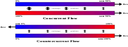
7. Parallel flow heat exchanger: In this type of heat exchanger fluid is flow in same direction. The hot fluid and cold fluid are entered in the same direction and exits to the other ends. This type of heat exchanger is also known as concurrent heat exchanger.
Fig 1: concurrent flow
8. Counter flow heat exchanger: The hot and cold fluids are flow to opposite to each other. If the hot fluid enter in one ends and cold fluid at the others ends.
Fig 2: counter flow heat exchanger
9. Cross flow heat exchanger: In this type of heat exchanger fluid is flow to each other at the right angle. In this fluid is flow cross to each other. At a time both the fluid are flow.
II.
LITERATURE REVIEW
A lot of research has been carried out on the parallel and counter flow heat exchanger. Z.H. Ayub, 2003 [1] presented the new correlations for evaporation heat transfer coefficient and friction factor for heat transfer and pressure drop correlations for refrigerant evaporators, which are applicable to various system pressure conditions and plate chevron angles. Plate heat exchangers are used regularly in the heating, ventilating air conditioning, and refrigeration industry. Here the correlations are based on actual field data collected during several years of installation and operation of chillers, and they are intended to serve as design tools and perhaps as a starting point for future research. Impact factor found in that research is 0.69. Yakut and Sahin. 2004 [2] were performing an experiment with the configuration of coiled wire cross section 4mm & length 1240 mm, by using air as a working fluid with the Reynolds no. varying from 5000 to 35000 and Pitches are 10, 20, 30 mm. they observe that Vortex characteristics of the tabulators should be considered as a selecting criterion with heat transfer and friction characteristics in heat transfer enhancement applications.
S.M. Pesteei et al. [3] were analysed local heat transfer coefficients on fin tube heat exchanger with winglets using a single heater. The size of single heater is 2 inch diameter and five different positions of winglet type vortex generators local heat transfer coefficients were measured. Measurements were made at Reynolds number about 2250. And by measuring the static pressure drop in the system flow losses were determined. Results showed a substantial increase in the heat transfer with winglet type vortex generators. It has been observed that average Nusselt number increases by about 46% while local heat transfer coefficient improves by several times as compared to plain fin tube heat exchanger. The maximum improvement is observed in the re-circulation zone. The best location of the winglets was with DX=0.5 D and DY=0.5 D. The increase in pressure drop for existing situation was of the order of 18%. S. Chomdee and T. Kiatsiriroat, 2006 [4]
315
Copyright © 2011-15. Vandana Publications. All Rights Reserved.
by delta winglet vortex generators in air cooled staggered array of rectangular electronic modules. The winglet vortex generators were placed in front of 3×5 (rows and columns) modules with 20° attack angle. Each module had dimensions of 1.8×5.4×0.6 cm and each one generates a heat at 2.5 W. C.B. Allison et al. [5] investigated the experimental analysis of the effects of delta-winglet vortex generators on the performance of a fin and tube radiator is presented. The winglets were arranged in flow-up configuration, and placed directly upstream of the tube. This is a hitherto untested configuration, but is thought to have certain advantages. In addition to vortex generation the flow is guided onto the tube surface increasing the localised velocity gradients and Nusselt numbers in this region. The study includes dye visualisation and full scale heat transfer performance measurements. The results are compared to a standard louvre fin surface. It was found that the winglet surface had 87% of the heat transfer capacity but only 53% of the pressure drop of the louvre fin surface. They found that the heat transfer mechanisms of the two fin surfaces differ dramatically. The louver fin surface facilitates boundary layer renewal and has numerous leading edges. The delta-winglet fin has fewer leading edges and relies predominantly on increasing convection through vortex generation. According to the results, the louver fin is superior to the delta winglet fin. Although coherent vortices were generated from the first row of winglets, we doubt whether the downstream winglets produce the same level of vorticity. This implies that only the first row of winglets may be effective in producing vortices which can improve heat transfer. Amab Kumar De and Amaresh Dalal, 2007 [6] studied computationally on laminar flow and heat transfer past a triangular cylinder placed in a horizontal channel (For the Range 80 ≤ Re ≤ 200 and Blockage ratio 1/12 ≤ β ≤ 1/3). A second-order accurate finite volume method with non-staggered arrangement of variables employing momentum interpolation for the pressure-velocity coupling was used.
Mohammad Javad Hosseini & Kurosh Sedighi, 2008 [7]
numerically investigated the mixed convection heat transfer and the fluid flow in the Poiseulle–Benard Channel with wall-mounted obstacles. The UTFN [Nourollahi 2007] code was used to solve the momentum and energy equations. The result had shown that with the increase of the wall-mounted obstacles over the channel wall, the Nusselt number increases as compared to the simple channel. On the other hand, the number of the obstacles was not directly proportional Nusselt number. Though the maximum Nusselt number was achieved by the optimize number of the obstacles. P.Promvonge. 2008 [8] by using air as the test fluid in circular tube he experimentally investigated that the influences of insertion of wire coils in conjunction with twisted tapes on heat transfer and turbulent flow friction characteristics in a uniform heat flux. To create a continuous impinging swirl flow along the tube wall, the twisted tape is inserted into the wire coil and the wire coil used as a turbulator is placed inside the test tube. The effects of insertion of the two turbulators with different coil pitch and twist ratios on heat transfer and friction loss in the tube are examined for Reynolds number
ranging from 3000 to 18000. After that experimental results are compared with those obtained from using wire coil alone, apart from smooth tube. The results indicate that the presence of wire coils together with twisted tapes leads to a double increase in heat transfer over the use of wire coil alone. The combined twisted tape and wire coil with smaller twist and pitch ratios provides higher heat transfer rate than those with larger twist and coil pitch ratios under the same conditions. Also, performance evaluation criteria to assess the real benefits in using both the wire coil and the twisted tape of the enhanced tube are presented. Oguz Turgut, Nevzat Onur, 2009 [9]
experimental and three dimensional numerical work was carried out to determine the average heat transfer coefficients for forced convection air flow over a rectangular flat plate. Three dimensional numerical simulations were obtained using a commercial finite volume based fluid dynamics code called Fluent 6.3. The experiments were performed for mass transfer using the naphthalene sublimation technique. The results were presented in terms of heat transfer parameters using the analogy between heat and mass transfer. All the experimental results were correlated within an accuracy of ± 12%. Mao Yu Wen et al. [10] presented the information of an experimental design on the elements of the fin and tube heat exchanger. In this study the three different types of the fin design were proposed (plate fin, wavy fin, and compounded fin) and investigated. The heat transfer coefficient, the pressure drop of the air side, the Colburn factor (j), and fanning friction factor (f) against air velocity (1-3 m/s) and Reynolds number (600-2000) have been discussed in this paper. Air was driven by a 1.0 HP frequency adjusted axial blower from a wind tunnel within a test section. The test section was constructed by using a commercial plexi glass plate, 5 mm thick. The dimension of the test section was 270 mm (width), 270 mm (height) and 850 mm (length). The heat source was supplied by a hot water thermostat reservoir. Khairun, Hasmadi and Othman, 2009 [11] used the computational fluid dynamic (CFD) for solving and analyzing problems involved in the heat exchanger. The work on the shell and tube heat exchanger because this type of heat exchanger is mostly ue4sd in the oil refinery and the chemical processes. It is used because they have high pressure application. They used the CFD package Gambit 2.4 and then the Fluent 6.2 for the simulation of the experimental result. The following processes are used in the fluent for simulation of the experimental parameters. This present the simulation of heat transfer in the shell and tube heat exchanger and used the heat exchanger model (MODEL HE 667) that is used in the UMP’s chemical engineering laboratory. The CFD model is used by the comparison to the experimental result with 15% error. M.A. Akhavan-behabadi et al. 2009 [12]
316
Copyright © 2011-15. Vandana Publications. All Rights Reserved.
the coil pitch made a moderate decrease in performance parameter. Cardone and Panelli, 2010 [13] experimentally investigated the effect of periodic patterns of protrusions (ribs) on the free-convection heat transfer in a vertical plate with uniform heat flux rate boundary condition. The result shows that the use of periodic pattern of ribs placed on a vertical flat plate in natural convection improves convective heat transfer to its maximum. The above literature survey shows that the numerous experimental and theoretical studies have been performed to enhance heat transfer in the channel flow and on electronic circuit board; however there is still a room to discuss. Jiong Li et al. [14] proposed the numerical analysis of a slit fin and tube heat exchanger with longitudinal vortex generator. A 3D numerical simulation is performed on laminar heat transfer and flow characteristics of a slit fin and tube heat exchanger with longitudinal vortex generator. Heat transfer enhancement of novel slit fin mechanism is investigated by examining the effects of strips and the longitudinal vortices. Slit fins are same like some pieces of strips are punched from the fin sheet. Y. Chen et al. [15] investigated the effect of punched longitudinal vortex generator in form of winglets staggered arrangements to enhance the heat transfer in high performance finned oval tube heat exchanger. Winglets in staggered arrangement bring larger heat transfer enhancement than in inline arrangement. K. Torii et al., propose a novel technique that can augment heat transfer but nevertheless can reduce pressure-loss in a fin tube heat exchanger with circular tubes. The winglets are placed with a heretofore-unused orientation for the purpose of augmentation of heat transfer. This orientation is called as ‘‘common flow up’’ configuration. The proposed configuration causes significant separation delay, reduces form drag, and removes the zone of poor heat transfer from the near-wake of the tubes. Jin-Sheng Leu et al., numerically and experimentally analyses the heat transfer and flow in the plate-fin and tube heat exchangers with inclined block shape vortex generators mounted behind the tubes. The results indicated that the proposed heat transfer enhancement technique is able to generate longitudinal vortices and to improve the heat transfer performance in the wake regions. Y.L. He et al. [16] proposed the numerical analysis of heat-transfer enhancement by punched winglet type vortex generator arrays in fin and tube heat exchanger. The potential of punched winglet type vortex generator arrays is use to enhance air side heat transfer performance of finned tube heat exchanger. The array is composed of two delta winglet pairs with two layout modes of continuous and discontinuous winglets. For the punched Vortex generator cases, the effectiveness of the main vortex to the heat transfer enhancement is not fully dominant while the “corner vortex” also shows significant effect on the heat transfer performance. Two kinds of VG arrays and a conventional VG configuration in common flow up arrangement are performed in this numerical study. The designs parameters such as punching effects, attack angle and placement locations of delta winglet on the flow and heat transfer characteristics were examined. M.V. Ghori and R.K. Kirar, 2012 [17] both
317
Copyright © 2011-15. Vandana Publications. All Rights Reserved.
the least cost. Dhananjay Kumar*1, Prof. Alok choube2 2014 [20] examined heat transfer enhancement in fin tube heat exchanger by vortex generator. They used different type of vortex generator like delta winglet, rectangular winglet, curved trapezoidal winglet pair. The vortex generator can be embedded in the plate fin and that too in a low cost with effect the original design and setup of the commonly used heat exchangers. The various design modifications which are implemented and studied numerically and experimentally. Swapnil Ahire, Purushottam Shelke, Bhalchandra Shinde, Nilesh Totala, 2014 [21] fabricated and analysed counter flow helical coil heat exchanger. Firstly they analysed the counter flow heat exchanger and then variations of various dimensionless numbers i.e. Reynolds Number, Nusselt’s Number and Dean’s number are studied. It was found that the centrifugal force due to the curvature of the tube results in the secondary flow development which enhances the heat transfer rate. This phenomenon can be beneficial especially in laminar flow regime. The overall effect of these parameters on Nu and hi is presented in this paper. The analysis shows that, for low Re, the graphs of Nu Vs Re and hi Vs Re is steeper than that at high Re. It indicates that helical coils are efficient in low Re. As well as the graph shows as coolant velocity increases the slope of the graph increases. This implies that if flow rate of coolant is increased, the rate of increase of heat transfer coefficient with Reynolds number increases. Ravindra Kumar, Mohd. Islam and M.M. Hasan, 2014 [22] experimentally investigated on heat transfer characteristics of single phase liquid flow in micro channels. Size of micro-electro mechanical system (MEMS) is reducing day by day and power density of micro devices is increasing, posing a problem for thermal control and heat dissipation from these devices. Here it has been observed that Nano fluids as coolants in micro channels have excellent potential to enhance the heat transfer performance and are quickly establishing as future coolant to be reckoned with.
III.
PROBLEM FORMULATION
Literature review shows that many experimental and theoretical attempts have been made to heat transfer enhancement in laminar separated flows and various attempts have been made in study of forced convection and plate finned heat exchangers. No attempts so far has been made to experimental analysis of heat exchanger and simulation of result using solid works.
IV.
EXPERIMENTAL SETUP
A schematic diagram of the experimental apparatus is presented in Figure 3. This experiment consisted a shell - tube heat exchanger which apply for a counter and a parallel flow to a compact heat exchanger. The first setup consisted in setting up a counter flow in the heat exchanger. The schematic steps for the counter flow. Four thermocouples are connected, two to the pipe inlets and two to the outlet pipes. A pump will drive the water through a heater which will increase the waters
temperature in a closed loop. The cold water will be provided externally at room temperature. Two volumetric flow meters will measure the speed of volume running through each circuit of fluid. Five values were obtained from each of the four thermocouples.
The same procedure was applied in the second part, except that the fluid was connected in a parallel way. Five measurements of temperature were registered for each thermocouple connected to the system.
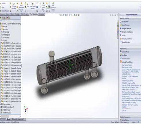
Figure 3: Shell and tube heat exchanger setup
V.
CFD ANALYSIS BY SOLID WORK
First working on the geometry, and assembling the parts of the heat exchangers. Then we work on the meshing of the data on the software for run the input data for the getting the result. This process is known as flow simulation.
318
Copyright © 2011-15. Vandana Publications. All Rights Reserved.
Counter-flow Result:Maximum criteria for the temperature and mass flow rate
Name Unit Value Progre ss
Use in converge
nce
Delta Criter ia
GG Max Temperatu re (Fluid) 1
°C 39.00 7 On 0.000439 178846
3.115 9966 8e-05
GG Mass Flow Rate
1
kg/s 3.985 7e-05
100 On 1.333505 23e-06
0.002 6802 176
Min/Max Table:
Minimum and maximum value for fluids in counter flow
Name Minimum Maximum
Pressure [Pa] 101308.61 101356.19
Temperature [°C] 27.00 39.00
Density [kg/m^3] 991.79 995.70
Velocity [m/s] 0 0.061
Velocity (X) [m/s] -0.060 0.009
Velocity (Y) [m/s] -0.025 0.029
Velocity (Z) [m/s] -0.019 0.019
Temperature (Fluid) [°C]
27.00 39.00
Temperature (Solid) [°C]
27.24 38.54
Vorticity [1/s] 0 3.761
Shear Stress [Pa] 0 0.06
Heat Transfer Coefficient [W/m^2/K]
0 840.387
Surface Heat Flux [W/m^2]
-7293.169 6457.923
Overheat above Melting Temperature [K]
-1055.813 -1044.507
All the table helps for the simulation of the result in the solid works. After, the tables give the maximum or minimum values for the counter flow. This result is compare with the parallel flow and the overall heat transfer coefficient with experimental values.
Heat distribution at different range of temperature of fluid
Flow heat in shell and tube heat exchanger
Parallel Flow Result:
Maximum criteria for the temperature and mass flow rate
Name Unit Value Progres s
Use in converge
nce
Delta Criteria
GG Max Temperature
(Fluid) 1
°C 39.00 100 On 4.832643 01e-06
4.9918622 8e-06
GG Mass Flow Rate 1
kg/s -6.082 9e-07
100 On 1.742481 64e-06
0.0027002 4755
Min/Max Table:
Minimum and maximum value for fluids in parallel flow
Name Minimum Maximum
319
Copyright © 2011-15. Vandana Publications. All Rights Reserved.
Temperature [°C] 27.20 39.00
Density [kg/m^3] 991.79 995.64
Velocity [m/s] 0 0.061
Velocity (X) [m/s] -0.060 0.008
Velocity (Y) [m/s] -0.027 0.028
Velocity (Z) [m/s] -0.019 0.019
Temperature (Fluid) [°C]
27.20 39.00
Temperature (Solid) [°C]
28.38 37.78
Vorticity [1/s] 0 3.815
Shear Stress [Pa] 0 0.07
Heat Transfer Coefficient [W/m^2/K]
0 237.154
Surface Heat Flux [W/m^2]
-11660.288 3926.671
Overheat above Melting Temperature
[K]
-1054.672 -1045.271
Heat distribution at different temperature in parallel flow
Flow heat in shell and tube heat exchanger
VI.
DISCUSS AND CONCLUSION
By the experimental values and heat exchanger calculations we find the value of overall heat transfer coefficient, shear stress, heat flux, and the other factors
which are very helpful for the design of heat exchanger. We find the difference between the experimental value and the analytical value of overall heat transfer coefficient value. These differences are found due to fouling factor, cavitation and design of the heat exchanger. We also study the parallel and counter flow maximum and minimum safe value of the heat exchanger which one gives the better result and safe for works. We find the overall heat transfer coefficient value for the counter and parallel flow and good result are given by the counter flow. We also find the shear stress value of minimum and maximum value of the shell and tubes. At that shear stress values of heat exchanger easy to safe design of the heat exchanger. The shown the different flow trajectories at the approximate value of the temperature. We also find the maximum and minimum values of the heat exchanger are found by using the software simulation. This help for which one flow are used for the experiment.
VII.
REFERENCES
[1] Z. H. Ayub,(2003). Plate Heat Exchanger Literature Survey and New Heat Transfer and Pressure Drop Correlations for Refrigerant Evaporators. Heat Transfer Engineering 24, 3-16.
[2] K Yakut, B Sahin. The Effects of Vortex Characteristics on Performance of Coiled Wire Turbulators Used for Heat Transfer Augmentation. Applied Thermal Engineering 2004, Vol. 24, Pages 2427-2438.
[3] S.M. Pesteei, P.M.V. Subbarao, R.S. Agarwal, Experimental study of the effect of winglet location on heat transfer enhancement and pressure drop in fin-tube heat exchangers. Applied Thermal Engineering 25 (2005) 1684-1696.
[4] S. Chomdee, and T. Kiatsiriroat (2006), Enhancement of air cooling in staggered array of electronic modules by integrating delta winglet vortex generators, INTERNATIONAL COMMUNICATIONS IN Heat and MASS TRANSFER,33,618-626.
[5] C.B. Allison, B.B. Dally, Effect of a delta-winglet vortex pair on the performance of a tube-fin heat exchanger. International Journal of Heat and Mass Transfer 50 (2007) 5065-5072.
[6] Arnab Kumar De and Amaresh Dalal (2007),Numerical Study of Laminar Forced Convection Fluid Flow And Heat Transfer From A Triangular Cylinder Placed In A Channel, ASME, Vol. 129.
[7] Mohammad Javad Hosseini, Mousa Farhadi, and Kurosh Sedighi (2008), Effect of Wall-Mounted Obstacles on Convective Heat Transfer in the Poiseulle– Benard Channel, Facta Universitatis Series: Mechanical Engineering ,Vol. 6, No 1, pp. 25-36.
320
Copyright © 2011-15. Vandana Publications. All Rights Reserved.
Heat Transfer on Solar Collector Surface. International communications in Heat and Mass Transfer, 36, 274-279. [10] Mao- Yu Wena and Ching-Yen Ho. Heat transfer enhancement in fin and tube heat exchanger with improved fin design. Applied Thermal Engineering. 29 (2009) 1050-1057.
[11] KHAIRUN HASMADI OTHMAN Chemical Engineering (Gas Technology), Chemical and Natural Resources Engineering, APRIL 2009
[12] MA Akhavan- Behabadi, R. Kumar, MR Salimpour, R. Azimi. Pressure Drop and Heat Transfer Augmentation due to Coiled Wire Inserts during Laminar Flow of Oil Inside a Horizontal Tube. International Journal of Thermal Sciences 2010;49:373-379.
[13] G. Cardone and M. Panelli (2010), Heat Transfer Enhancement with Ribs in Natural Convection’ 10th International Conference on Quantitative Infrared Thermography Québec (Canada) July 27-30.
[14] Jiong Li, Shuangfeng Wang, Jinfang Chen and Yong-Gang Lei. Numerical analysis of a slit fin and tube heat exchanger with longitudinal vortex generator. International Journal of Heat and Mass Transfer. 54 (2011) 1743-1751. [15] Y. Chen, M. Fiebig and N.K. Mitra. Heat transfer enhancement of finned oval tubes with staggered punched longitudinal vortex generators. International Journal of Heat and Mass Transfer. 43 (2000) 417-435.
[16] Y.L. H. Han, W.Q. Tao and Y.W. Zhang. Numerical analysis of heat-transfer enhancement by punched winglet type vortex generator arrays in fin and tube heat exchanger. International Journal of Heat and Mass Transfer. 55 (2012) 5449-5458.
[17] M.V.Ghori & R.k. kirar “numerical analysis of tube fine heat exchanger using fluent” ISSN:2319-3182 VOLUME 1 ISSUE 2,2012.
[18] Ya-Ling He, Pan Chu, Wen-Quan Tao, Yu-Wen Zhang, Tao Xie, Analysis of heat transfer and pressure drop for fin and tube heat exchangers with rectangular. [19] A.R.A. Khaled, “Analysis of heat transfer inside counter-flow plate heat exchanger augmented by an auxiliary fluid flow”. The Scientific World Journal (2014) volume 2014, ID-308545.
[20] Dhananjay Kumar, Prof. Alok Choube,(2014). Experimental Study of Heat Transfer Enhancement in Fin Tube Heat Exchanger by Vortex Generator. International Journal of Engineering Sciences & Research Technology, ISSN 2277-9655,Vol.3(5), Pages 186-192.
[21] Swapnil Ahire, Purushottam Shelke, Bhalchandra Shinde, Nilesh Totala,(2014). Fabrication and Analysis of Counter Flow Helical Coil Heat Exchanger. International Journal of Engineering Trends and Technology,ISSN 2231-5381, Volume 15, Number 5, Pages 229-240.