ISSN: 2278 – 7798 All Rights Reserved © 2015 IJSETR 3873
INDIRECT MATRIX CONVERTER WITH TWO POWER
SOURCES
Mohammed Abdul Rahman Uzair1, Mohd Abdul Sabeel2, Mohammed Ismail Ahmed3, Mohd Khaja Shujauddin4
¹ Associate Professor, Nawab Shah Alam Khan College of Engineering and Technology, Malakpet - Hyderabad, T.S., INDIA. 2
Graduate, Nawab Shah Alam Khan College of Engineering and Technology, Malakpet - Hyderabad, T. S., INDIA. 3
Graduate, Nawab Shah Alam Khan College of Engineering and Technology, Malakpet - Hyderabad, T. S., INDIA. 4
Graduate, Nawab Shah Alam Khan College of Engineering and Technology, Malakpet - Hyderabad, T. S., INDIA.
ABSTRACT: In the proposed paper, an indirect matrix converter (IMC) connected with two input power sources is proposed. A gasoline generator is used as the main AC power supply and batteries are used as the secondary power source. The IMC is small in size since it has a DC-link part without an electrolytic capacitor. The DC-link part is utilized by connecting it to a boost-up chopper with batteries as secondary input power source. Further, the chopper connects to the neutral point of the motor and utilizes the leakage inductance of the motor as reactor component. The proposed technique successfully further reduces the size of the converter by removing the boost reactor in the boost converter stage. The proposed converter is simulated such that the total harmonic distortion of the input and output currents are 4% and 3.7%, respectively and the efficiency is 96%. By removing the electrolytic capacitor and the boost-up reactor, the remaining part of the proposed circuit is constructed only of silicon components namely IGBTs and diodes. As a result, the proposed circuit is highly efficient and highly reliable.
Keywords: Converter, Boost Converter, Back to Back Converter, Fly-back Converter, Indirect Matrix Converter.
I.INTRODUCTION
One of the most commonly applied converters in hybrid systems is the AC/DC/AC converter because it has the ability to connect two different power sources. Fig. 1 shows a conventional AC/DC/AC power converter, which typically consists of a Pulse Width Modulation (PWM) rectifier, a DC-link capacitor, and a PWM inverter- together called Back-to-Back (BTB) system. The PWM rectifier is often used to reduce the harmonic currents in a generator and control the DC-link voltage. A typical method for reducing the voltage fluctuation is to place a large electrolytic capacitor into the DC-link part as a filtering device between the rectifier and the inverter.
However, a large electrolytic capacitor is bulky. An alternative approach is to reduce the capacity of the
electrolytic capacitor by the application of a high-speed DC-voltage controller to the rectifier control. However, the control response is limited by the delay of the voltage detection and digital controller. Therefore, the electrolytic capacitor is still required. In addition, the capacitance is not reduced since the DC-link capacitor is dominated by the capacitor current.
As a result, a large amount of space is required for the capacitor installation in a practical device. In addition, electrolytic capacitors are not suitable for high-temperature applications such as those in HEVs. Overall, these disadvantages of the electrolytic capacitor affect the reliability of the converter. For the secondary input power source, a boost converter that consists of a boost reactor and a switching leg [insulated gate bipolar transistor (IGBT)] is connected with batteries to the DC link part of the BTB system. Boost converter will control the battery current and the battery power will be used as a secondary power to drive the electric motor.
In the proposed paper, a new circuit topology is presented, which is composed of an Indirect Matrix Converter (IMC) and a DC/DC boost converter that connects to the neutral point of a motor. An IMC has high efficiency and is easily configured in comparison to the matrix converters. Also, this converter does not require a DC-link electrolytic capacitor to filter the DC-ripple voltage. It uses a direct conversion technique where the frequency of the DC-link voltage contains a ripple six times the input frequency. However, the output voltage transfer ratio is limited by this direct conversion technique which is similar to the matrix converter, where output voltage = 0.866 of the input voltage.
II. CONVERTER
Single phase uncontrolled rectifiers are extensively used in a number of power electronic based converters. In most cases, they are used to provide an intermediate unregulated DC voltage source which is further processed to obtain a regulated DC or AC output. They have, in general, been proved to be efficient and robust power stages. However, they have a few disadvantages the main being their inability to control the output DC voltage / current magnitude when the input AC voltage and load parameters remain fixed. They are also unidirectional in the sense that they allow
ISSN: 2278 – 7798 All Rights Reserved © 2015 IJSETR 3874 electrical power to flow from the AC side to the DC side
only. These two disadvantages are the direct consequences of using power diodes in these converters which can block voltage only in one direction. As will be shown in this module, these two disadvantages are overcome if the diodes are replaced by thyristors. The resulting converters are called fully controlled converters.
Thyristors are semi controlled devices which can be turned ON by applying a current pulse at its gate terminal at a desired instance. However, they cannot be turned OFF from the gate terminals. Therefore, the fully controlled converter continues to exhibit load dependent output voltage / current waveforms as in the case of their uncontrolled counterpart. However, since the thyristor can block forward voltage, the output voltage / current magnitude can be controlled by controlling the turn on instants of the thyristors [1].
III. BOOST CONVERTER
A boost converter (step-up converter) is a power converter with an output DC voltage greater than its input DC voltage. It is a class of Switching-Mode Power Supply (SMPS) containing at least two semiconductor switches (a diode and a transistor) and at least one energy storage element. Filters made of capacitors (sometimes in combination with inductors) are normally added to the output of the converter to reduce output voltage ripple.
Figure1: Boost converter
Power can also be supplied from DC sources such as batteries, solar panels, rectifiers and DC generators. A process that changes one DC voltage to a different DC voltage is called DC to DC conversion. A boost converter is a DC to DC converter with an output voltage greater than the source voltage. A boost converter is sometimes called a step-up converter since it “steps up” the source voltage. Since power (P = VI or P = UI in Europe) must be conserved, the output current is lower than the source current [2].
A boost converter may also be referred to as a 'Joule thief'. This term is usually used only with very low power battery applications and is aimed at the ability of a boost converter to 'steal' the remaining energy in a battery. This energy would otherwise be wasted since a normal load wouldn't be able to handle the battery's low voltage.
This energy would otherwise remain untapped because in most low-frequency applications, currents will not flow through a load without a significant difference of potential between the two poles of the source (voltage).
IV. BACK TO BACK CONVERTER
A conventional AC/DC/AC power converter typically consists of a pulse width modulation (PWM) rectifier, a DC-link capacitor and a PWM inverter also known as a Back to-Back (BTB) system [3].
Figure2: Back to Back Converter
V. CUK CONVERTER
The buck, boost and buck-boost converters transfer energy from input and output using the inductor whose analysis is based on voltage balance across the inductor. The CUK converter uses capacitive energy transfer and analysis is based on current balance of the capacitor. The circuit in below (CUK converter) is derived from DUALITY principle on the buck-boost converter.
Figure3: CUK Converter
If we assume that the current through the inductors is essentially ripple-free, we can examine the charge balance for the capacitor C1. For the transistor ON the circuit becomes as shown in Fig.4 below.
Figure4: CUK "ON-STATE"
ISSN: 2278 – 7798 All Rights Reserved © 2015 IJSETR 3875 Since the steady state assumes no net capacitor voltage rise,
the net current is zero.
……… (24) The above equation implies
…….. (25)
The inductor currents match the input and output currents, thus using the power conservation rule, we can write
………… (26)
Thus, the voltage ratio is the same as that of buck-boost converter. The advantage of the CUK converter is that the input and output inductors create a smooth current at both sides of the converter while the buck, boost and buck-boost have at least one side with pulsed current.
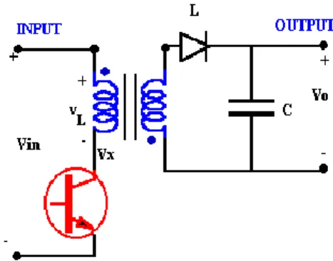
VI. FLY-BACK CONVERTER
The fly-back converter can be developed as an extension of the Buck-Boost converter. Fig. 6(a) shows the basic converter. Fig. 6(b) replaces the inductor by a transformer. The buck-boost converter works by storing energy in the inductor during the ON phase and releasing it to the output during OFF phase. With the transformer the energy storage is in the magnetization of the transformer core. To increase the stored energy, a gapped core is often used. In Fig. 6(c), the isolated output is clarified by the removal of common reference of the input and output circuits.
Figure6(a): Buck-Boost Converter
Figure6(b): Replacing inductor by transformer
Figure 6(c): Fly-back converter re-configured
VII. INDIRECT MATRIX CONVERTER
Fig. 7 shows the proposed circuit configuration. The IMC can be simply divided into primary and secondary stages. The primary stage for the AC power source consists of 12 units of reverse-blocking IGBTs, also known as a current-source rectifier, where bi-directional power flow is possible in this circuit structure. An LC-filter is required at the input of the primary stage for smoothing the input current. The secondary stage for the motor consists of six IGBT units which is similar to a standard voltage source inverter. The advantage of this converter over a BTB is that the primary side does not contain switching loss because zero-current switching can be applied. The switching timing of the primary side is considered during the zero-current period of the DC-link when secondary stage output voltage is zero. Therefore, high efficiency is achievable in this converter [4].
Figure7: Indirect Matrix Converter
The other reason to use the IMC is that the IMC has a DC-link part, which is different from the conventional matrix converter. The DC-link part is utilized by adding a boost converter to the IMC. The boost converter connects to the battery and the other terminal of the battery is then connected to the neutral point of the motor. A „Snubber‟ circuit is also included in the DC-link part to absorb the voltage overshoot from reactive elements in the circuit .It is used to prevent damage to the switching devices in the secondary side due to a sudden large voltage. It should be noted that the capacity of the snubber capacitor is smaller than the DC-link capacitor in a BTB system because the ripple current of the DC-link part does not flow in the snubber capacitor. The chopper circuit is connected in the
ISSN: 2278 – 7798 All Rights Reserved © 2015 IJSETR 3876 DC link and batteries are connected to the neutral point of
the motor. The leakage inductance of the motor is used as a boost-up reactor in the proposed circuit. As a result, the proposed converter does not require bulky passive components.
VIII. CONTROL STRATEGY
The primary side, the DC chopper and the secondary side are individually controlled by their own commands. A carrier comparison method is used as the PWM modulation, according to the control strategy. The secondary side operates as a four-phase voltage-source inverter by addition of the DC chopper as the fourth leg where 𝑆𝑥𝑦 represents the
switching function of the switches. When Sxy is turned ON, 𝑆𝑥𝑦 = 1 and when 𝑆𝑥𝑦 is turned OFF, 𝑆𝑥𝑦= 0.
Primary-Side Control:
The primary-side controller is designed with a current-type PWM rectifier command. It uses a pulse-pattern conversion to convert PWM pulses of the voltage source type into PWM pulse of the current source type by a simple logic selector. It uses a single-leg modulation where the switching period can be reduced from 2𝛱3 to 𝛱3 , where the 2𝛱3 is the
switching period of the conventional two-phase modulation. That is, the leg with the maximum input phase voltage will always be turned ON and the other two legs will be always turned OFF. When the maximum input phase voltage is changing, (for example, from +R-phase to −S-phase), the related max phase voltage leg and the mid phase voltage leg will be switched at zero current until the relevant switch that contains the mid phase voltage becomes the maximum input phase voltage. From this direct conversion technique, a DC-link voltage that contains a ripple six times the input frequency will be formed.
Secondary-Side Control:
A conventional controller method for a voltage-source-type inverter is applied to the DC chopper and the inverter with a lean-controlled carrier modulation. The carrier modulation forms a new carrier, where the peak position of the triangular carrier is controlled by the duty ratio of rectifier-side pulse. This rectifier pulse is used to control the switching timing of the primary stage and the zero-vector of the secondary stage. From the control, zero-current switching is achieved in the primary stage, where the DC-link current becomes zero at the peak of every carrier. This new carrier is then used in the secondary side and the DC chopper side as a normal PWM comparison method, also referred to as an inverter carrier. The Boost Converter is not a stand-alone circuit in the proposed circuit. Operation is strongly dependent on the secondary side of IMC. Zero-vector outputs on the secondary side are the key factors to link the Boost Converter to the IMC. The zero vector controls the amplitude of the output voltage. There are two functions of the zero-vector output to the secondary side. The first one is to implement zero-current switching on the primary side so that the switching losses do not occur at the primary side. The second function involves operation of the boost converter.
The relationship between the normal carrier applied to the primary side and the new inverter carrier applied to the secondary side. The inverter commands are given by the voltage controller. It is noted that the DC chopper is controlled as the fourth leg of the inverter so that the DC chopper command is compared by the same carrier with the inverter voltage commands. There are two methods to generate an inverter carrier in the bottom peak position of the triangular carrier which is controlled by the duty ratio of the rectifier pulse. The chopper commands along with the inverter output voltage commands are compared with this new inverter carrier to obtain the desired switching patterns. The zero-vector periods of the switching pulses of the secondary side attain the zero vectors for every carrier cycle. The primary side arms switch at every zero-vector period. Zvu and Zvl represent the zero-vector periods of the inverter,
where Zvu = Sup = Svp= Swp= 1 (upper arm zero vector) and Zvl = Sup = Svp= Swp= 0[lower arm zero vector (Sun = Svn= Swn= 1)]. The upper arm of the chopper (Scp) switches ON at every zero-vector period of Zvu. On the other hand, the lower
arm of the chopper (Scn) will switch ON at every zero-vector periods of Zvl. During these zero-vector periods, the boost
converter is operated in the ON-state, and the battery current through the leakage inductance of the motor increases. During the non-zero vector periods, also known as the OFF-state operation, the battery current is released into relationship between the zero vectors and boost converter operation.
The operation state in this is referred to the boost converter operation. When the switching frequency of the rectifier is 10 kHz, the control method applied generates a new symmetrical carrier that has a frequency of approximately 20 kHz. This is almost twice the primary-side switching frequency. Alternatively, according to an inverter carrier can be formed based on the duty of the rectifier command which is asymmetrical with a frequency of 10 kHz. By comparing the symmetrical and asymmetrical inverter carriers, it can be noted that the zero-current switching in the rectifier is not affected by the inverter carrier because both carriers are formed following the rectifier duty. Since every carrier time is longer in the asymmetrical inverter carrier, the sequence of the zero-vector periods becomes slower. Therefore, the boost converter will achieve better efficiency but the current ripple in the battery will increase. Further, the asymmetrical method can achieve better total harmonic distortion (THD) values for the output because the dead time effect is smaller due to the lower switching frequency. The other disadvantage of the asymmetrical inverter carrier is the detection of the load current. Usually, the average value of the load current appears at the peak of the symmetrical inverter carrier so that it can be easily detected using the symmetrical inverter carrier. However, for the asymmetrical carrier, the average current point does not agree with the peak of the asymmetrical carrier. Hence, in order to detect the average current, a low-pass filter is required. Consequently, control performance will be decreased.
IX. RESULTS
The results are shown in the following Figures 8.1, 8.2, 8.3 and 8.4.
ISSN: 2278 – 7798 All Rights Reserved © 2015 IJSETR 3877
Figure8.1: Input voltage
Figure8.2: Voltage and current at secondary side
Figure8.3: Output voltage before LP 2nd order filter
Figure8.4: Voltage available at the motor
Advantages:
1. The switching timing of the primary side is during the zero-current period of the DC-link when the secondary
stage output voltage is zero. Therefore, high efficiency is achievable in this converter.
2. IMC has a DC-link part which is different from the conventional matrix converter. The DC-link part is utilized by adding a boost converter to the IMC.
3. The boost converter connects to the battery and the other terminal of the battery is then connected to the neutral point of the motor.
4. A „snubber‟ circuit is also included in the DC-link part to absorb the voltage overshoot from reactive elements in the circuit.
Applications:
1. A new control method is proposed by utilizing the neutral point of a motor and connection to an IMC for motor drive applications.
2. Simulation and experimental results demonstrated good sinusoidal waveforms and confirmed the validity of the proposed method.
3. From the loss analysis of the proposed circuit, an efficiency of 96% was estimated.
X.CONCLUSION
A new control method is proposed in this paper by utilizing the neutral point of a motor and connection to an Indirect Matrix Converter for motor drive applications. Control over the inverter zero-vector periods allows an additional chopper leg to perform as a boost converter with connection to the neutral point of a motor. Simulation and experimental results demonstrated good sinusoidal waveforms and confirmed the validity of the proposed method. From the loss analysis of the proposed circuit, an efficiency of 96% was estimated.
The proposed circuit is composed of an indirect matrix converter (IMC) and a DC/DC boost converter that connects to the neutral point of a motor. The IMC has a DC-link part which is different from the conventional matrix converter. The DC-link part is utilized by adding a boost converter to the IMC. A „snubber‟ circuit is also included in the DC-link part to absorb the voltage overshoot from reactive elements in the circuit.
ACKNOWLEDGMENT
Mohammed Abdul Rahman Uzair is thankful to all the co-authors for their help in coming up with an innovative paper. Mohd Abdul Sabeel is thankful to the co-authors for their support in preparing this paper.
Mohammed Ismail Ahmed expresses thanks to the co-authors for their support in preparing this paper.
Mohammed Khaja Shujauddin is thankful to all the people responsible for the publication of this paper.
ISSN: 2278 – 7798 All Rights Reserved © 2015 IJSETR 3878 REFERENCES
[1] R. Ghosh and G. Narayanan, “Control of three-phase, four-wire PWM rectifier,” IEEE Trans. Power Electron., vol. 23, no. 1, pp. 96–106, Jan. 2008.
[2] X. H.Wu, S. K. Panda, and J. X. Xu, “Analysis of the instantaneous power flowfor three-phasePWM boost rectifier under unbalanced supply voltage conditions,” IEEE Trans. Power Electron., vol. 23, no. 4, pp. 1679–1691, Jul. 2008.
[3] D. Casadei, G. Grandi, C. Rossi, A. Trentin, and L. Zarri, “Comparison between Back-to-Back and matrix converters based on thermal stress of the switches,” in Proc. IEEE Int. Symp. Ind. Electron., May 2004, vol. 2, pp. 1081– 1086.
[4] M. Jussila and H. Tuusa, “Comparison of simple control strategies of space-vector modulated indirect matrix converter under distorted supply voltage,” IEEE Trans. Power Electron., vol. 22, no. 1, pp. 139–148, Jan. 2007.
Mohammed Abdul Rahman Uzair was born at Nalgonda, a district headquarter nearly 100kms from Hyderabad, India. He completed his B. Tech in Electrical and Electronics Engineering from JNTU Hyderabad in the year 2003. He completed his M. Tech in Electrical Power Engineering from JNTU Hyderabad in the year 2012. Currently, he is pursuing PhD from GITAM University, Hyderabad campus on the topic „Failure Analysis of Power Transformers‟. He is working as Associate Professor in the Department of EEE at Nawab Shah Alam Khan College of Engg & Tech, Hyderabad. His fields of interest are Power Systems and Power Electronics. He has published one paper in a National Journal and eleven papers in International Journals.
Mohd Abdul Sabeel was born at Hyderabad, India. He completed his B. Tech in Electrical and Electronics Engineering from JNTU, Hyderabad in the year 2015. He secured overall 73 percent in B. Tech. His fields of interest are Power Systems, Distribution Systems, Power Electronics and Electrical Machines.
Mohammed Ismail Ahmed was born at Hyderabad, India. He completed his B. Tech in Electrical and Electronics Engineering from JNTU, Hyderabad in the year 2015. He secured overall 70 percent in B. Tech. His fields of interest are Power Systems, Power Electronics, Renewable Energy Sources and Electrical Machines.
Mohammed Khaja Shujauddin was born at Hyderabad, India. He completed his B. Tech in Electrical and Electronics Engineering from JNTU, Hyderabad in the year 2015. He secured overall 82 percent in B. Tech. He has published one paper in an International journal so far. His
fields of interest are Power Systems, Control Systems and Electrical Machines.