Volume: 03, Issue: 04
(JULY
–
AUGUST, 2017)
168
Field Oriented Control for DFIG Based Wind Energy Conversion System
Saurabh Gupta1, S.C. Choube2, Sushma Gupta3 1, 2 Department of Electrical & Electronics Engineering 1, 2 University Institute of Technology-RGPV Bhopal-462033 India 3Department of Electrical Engineering, MANIT Bhopal -462003 India
1saurabhgupta.sgsits[at]gmail[dot]com, 2scchoube[at]yahoo[dot]co[dot]in, 3sush_gupta[at]yahoo[dot]com
ABSTRACT: - The integration of alternating renewable energy sources into the electric grid presents various challenges in terms of power quality issues, voltage regulation and stability. Power quality relates to those factors which affect the variation of voltage level and distortion of the voltage and current waveforms which can cause severe adverse effects to the electric grid. The paper focuses on the design and evaluation of a field oriented vector control strategy for improving the quality of energy of a standalone grid-connected variable speed Doubly Fed Induction Generator (DFIG) wind energy conversion system. A field oriented control method for back to-back PWM converters in the DFIG is used for in this paper. The control scheme is implemented in the synchronous rotating reference frame and provides precise current control for both the GSC and RSC. The primary objective of the control scheme is to maintain constant voltage and frequency under variable operating conditions of load. The effectiveness of the coordinated control strategy is verified by the MATLAB simulation results on a 3.7-KW DFIG wind power generation system under harmonically distorted standalone voltage conditions.
Keywords: - Doubly fed induction generator, Field oriented control, Sensor less, Standalone Grid, Total Harmonic Distortion.
1.INTRODUCTION
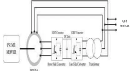
Both fixed speed squirrel cage induction and variable speed double fed induction generators are extensively used for Wind Energy conversion system. In modern times DFIG discover increasing application in wind-turbine generation. DFIG has the capability to control the active and reactive power and sustain constant frequency operation. With wind speed deviation or under power system disturbance, the injected rotor voltage, current or the frequency of the injected rotor voltage can be forced to achieve constant frequency, stable operation at the stator or grid side. Considering the prime mover characteristics, the wound rotor induction machine with field-oriented control is very attractive for high performance variable speed generation application. In this electric generator organization, the speed of the prime mover is allowed to vary within a certain range (sub synchronous and super synchronous mode) and the output of electrical power is always maintained at a constant voltage and constant frequency by controlling the slip power from the rotor terminals. An additional fundamental feature of this configuration is that the power converters have to handle the slip power and thus their rating is only a fraction of the total system power. Figure 1 shows the block diagram of a stand-alone generating system with
rotor side control. The bidirectional power flow capability is potential by the use of two back-to-back voltages source inverters through common dc link. The converters are referred as a rotor side converter and grid side converter. The grid side converter is also known as the front-end converter. A lot of work has been reported on the grid connected operation of such generators. The grid connected generator. The grid connected generator technology [1]–[7] is quite mature and is in wide use today. However, very little attention has been paid toward the issues of stand-alone generators. While more variable-speed generators are installed in wind farms, several new problems are introduced in power systems.
Figure 1. Basic block diagram of DFIG generator with back to back converter.
Most of the authors have explained the field oriented control scheme for the regulation of stator voltage and frequency. The stator voltage is regulated indirectly by controlling the magnetizing current of the machine, while the stator frequency is kept constant by impressing proper slip frequency currents from rotor terminals. All the schemes have used either speed or position sensor for the control. Recently, work has been reported which attempted sensor less control of a standalone doubly fed generator [9] based on the model reference adaptive system observer scheme. This paper presents a control scheme which addresses nearly all the features of the stand-alone generation system mentioned above [10]. The control scheme has dedicated voltage and frequency controllers to regulate stator voltage and frequency. The control scheme is novel and sensor less. It acts as a part of the frequency loop. The total control scheme has been simulated with the MATLAB Simulink. Detailed simulation results are presented to demonstrate and validate the control scheme.
2. CONTROL OF ROTOR SIDE CONVERTER
The control of the rotor side converter for a DFIG machine using a current-controlled PWM voltage source converter has been reported widely [1]–[7].
Volume: 03, Issue: 04
(JULY
–
AUGUST, 2017)
169 With a controlled converter at rotor terminals, rotor currents are controlled in amplitude, frequency by applying suitable rotor voltages from the rotor side converter.
The stator flux-oriented frame of reference is used for decoupling the active and reactive current control loops. The q-axis is aligned along the stator voltage vector leading the d-axis by 90◦ while the d-axis is aligned along the grid flux d-axis, (Figure 2). The d -axis controls the flux of the machine by controlling the reactive power flow, while q-axis current loop controls the torque of the machine by controlling the active power flow.
Figure 2. Vector diagram of field oriented control
The dynamic equations governing the rotor currents in the stator flux coordinates [1], [4] are as follows:
(4)
(5)
Where
and TR (= LR/RR) is the electrical time constant of the rotor circuit and σ (= 1 − (1/ (1 + σS) (1 + σR) is the total leakage factor of the machine. If the stator resistance drop is ignored, these can be taken as valid for grid flux also [1]. These equations are used to design the current control loops. The cross-coupling terms between the d-axis and q-axis (ωmS −ωe) σLRiRq
and (ωmS −ωe) σLRiRd and disturbance input (ωmS −
ωe) (1 − σ) LRimS are cancelled by feed forward
compensation and thereby independent control of d-axis and q-d-axis current loops is achieved by adding PI controllers in the loop. For the application of stand-alone generators, the broad objectives of the rotor side converter are:
1) establishment of a local grid; 2) changes of voltage and frequency;
3) reference generation for active (q) component of rotor current;
4) Sensor less control.
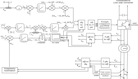
To achieve the objectives, a control strategy is implemented in rotor side converter through MATLAB Simulink.
Figure 3. Control Block Diagram of Rotor side Converter
2.1.REFERENCE GENERATION FOR Q-AXIS ROTOR CURRENT
LOOP
The active component iSq of the stator current is measured; the reference for the q component of the rotor current is set using
= - (1+σS) (6)
2.2.DESIGN OF VOLTAGE LOOP
The stator voltage is regulated by controlling the magnitude of the stator flux. The magnetizing current vector (imS) responsible for producing the stator flux is regulated to control the stator voltage magnitude. The equations governing the dynamics and steady state of the magnetizing Current are
s e
Rd i Ra i Rb i Rq ij
R
i e
S
u
ms m s
i
q axis
d axis
Stator flux axis Rotor flux axis Stator axis( ) (1 )
Rd Rd mS
R Rd mS e R Rq R
R
di u di
T i T i T
dt R dt
( ) ( )(1 )
Rq Rq
R Rq mS e R Rd mS e R mS
R
di u
T i T i T i
dt R
2
1 L L Lm s r
dq to ab ab to 3 ph Triangle comparison and PWM Generation
αβ to dq
3 ph to αβ
Unit vector generation method Ldh i Connected to Line side converter
IGBT conveter -cosθ sinθ WRIM
(mse) 1 s Sin table s u * s u -
(ms e) L iR Rq
(ms e) L iR Rd -1
(1S)
*
Rq
i
Rq
i
(mse)(1)L iR ms
Rd
i
(1s)
sd i sq i ms * ms Frequency Estimation 1 R i 2 R i 3 ph to αβ αβ to
dq RY u YB u sq i sd i 1 s i 2 s i Rq i Rd i integrator ( )
sin( ) cos( )
-* Rd i * ms i Rq
170
(7)
(8) The total magnetizing current imS, of the machine is supplied from the rotor side converter by d-axis rotor current iRd.
Figure 4. Vector Diagram of Stator side Converter
This is required as there is no initial grid. An external voltage loop is added such that the stator voltage is regulated by controlling the magnitude of imS through d-axis current control loop. The magnetizing current
imS controls the magnitude of uSq component of stator voltage which is leading it by 90 degree.
2. 3. Estimation of Grid Frequency and Design of Frequency Loop
A dedicated frequency loop is used to regulate the grid frequency. Frequency reference command is nominal grid frequency. Actual stator frequency is estimated using the feedback of the stator line to line voltages. Initially, unit vectors are generated using a unit vector generation scheme .With the information of unit vectors, the actual grid frequency is estimated using the following equation:
(9)
Output of the controller is the slip frequency command. This is the frequency at which the rotor voltage needs to be applied from the rotor side converter to maintain constant stator frequency.
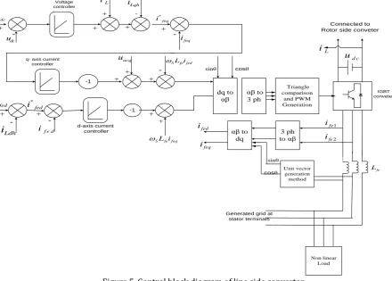
Figure 5. Control block diagram of line side converter
The prime mover speed variation is sensed indirectly in this scheme. Variation in prime mover speed will reflect in variation in grid frequency for a constant rotor frequency. The difference in frequency is sensed and corrective action is taken by the controller to bring back the stator frequency to the nominal set value.
3.CONTROLOFSTATORSIDECONVERTER
The objectives of the line side converter control in the standalone generator application are: (1) Regulation of dc link voltage; (2) clean unit vector generation; the line side converter is a current controlled voltage source converter. The principle of field-oriented control is used to achieve fast dynamic response. The
(1
)
mS Sd
S mS Rd
S
di
u
T
i
s
i
dt
R
(1
)
mS Sd Rd
i
s i
i
cos( )
sin( ) sin( )
cos( )
mS
d
d
dt
dt
-1
dq to
αβ
αβ to 3 ph
-1
Triangle comparison
and PWM Generation
αβ to dq
3 ph to αβ
Unit vector generation method
Non linear Load
fed
i
feq
i
1
fe
i
2
fe
i
fe L
SL ife feq
SL ife fed
dc
u *
dc
u
L
i
Lqh
i
Ldh
i
feq
i
acq
u
f e d
i
*
feq
i
'*
fed
i *
fed
i
d c
u
Connected to Rotor side conveter
IGBT conveter
Generated grid at stator terminals
Voltage controller
q- axis current controller
d-axis current controller
-
--
-L
i
cosθ sinθ
cosθ sinθ
-171 line currents are controlled in the rotating frame of reference attached to the stator voltage vector. The q-axis is aligned along the stator voltage vector, while d-axis is lagging it by 90◦ to maintain compatibility with the rotor side converter control (Figure 4).
3.1.VOLTAGE AND CURRENT LOOP
The equations governing the dynamics of line currents in the q- axis and d-axis [1], [4] are
(10)
(11)
Where (= ) is the time constant of line filter
impedance.
These equations are used to design inner current control loops. The d- and q-axis current loops responses are made independent by cancel out the cross-coupling terms (ωSLfeifed and ωSLfeifeq) and disturbance input (uacq) by introducing feed forward compensation in the loops. The control is achieved by
adding a PI controller in the loops. The equation governing the dynamics of the dc link is given by the following equation:
(12)
In the above equation, the load current iL acts as a disturbance input and is compensated using feed forward cancellation. The PI voltage controller is added external to q-axis current loop to regulate the dc link voltage.
4.SIMULATIONRESULTS
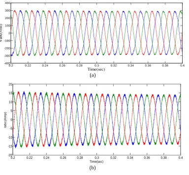
The simulation results are carried out using Matlab–
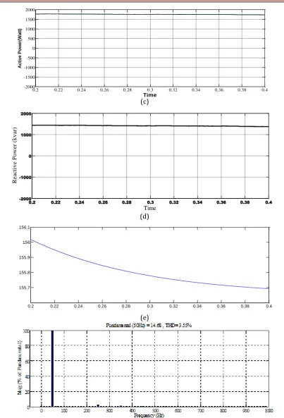
Simulink package, under a wind speed profile of (8 m/s) mean value, as depicted in in Figure 6. The stator voltages, stator currents and frequency are constant under these dynamic changes and are observed in Figure 6 (a) & (b). In Figure 6 (c) & (d) are displayed the active and reactive powers at the stator side of the DFIG. The other quantities generator speed and THD are also demonstrating the performance of output voltage and current for under variable load operation.
(a)
(b)
feq feq acq
fe feq s fe fed
fe fe
di
u
u
T
i
T i
dt
R
R
fed fed
fe fed s fe feq
fe
di
u
T
i
T i
dt
R
fe
T
fefe
L
R
(2 / 3)
acq dcfeq L dc
u
du
c
i
i
dt
u
0.2 0.22 0.24 0.26 0.28 0.3 0.32 0.34 0.36 0.38 0.4
-400 -300 -200 -100 0 100 200 300 400
Time(sec)
V
ab
c(v
o
lt
)
0.2 0.22 0.24 0.26 0.28 0.3 0.32 0.34 0.36 0.38 0.4 -20
-15 -10 -5 0 5 10 15 20
Time(sec)
Ia
b
c
(A
m
p
172 (c)
(d)
(e)
(f)
Figure 6. Simulated performance of(a) stator voltage (b) stator current (c) active power (d) reactive power (e) rotor speed (f) Total Harmonics Distortion of VFC for DFIG based under variable wind speed 8 m/s with PI controller (at
full load) in
5.CONCLUSION
This paper has presented a device intended to fit in a wind mill based on a Doubly Fed Induction Generator connected to the grid. After a description of this device and its connection procedure, we have established a two-phase mathematical model of the DFIG. In order to
control stator active and reactive power exchanged between the DFIG and the grid, a vector-control strategy has been presented. A vector control scheme for grid connected generators based on a wound rotor induction machine with rotor side control has been
0.2 0.22 0.24 0.26 0.28 0.3 0.32 0.34 0.36 0.38 0.4 -2000
-1500 -1000 -500 0 500 1000 1500 2000
Time
A
c
ti
v
e
P
o
w
e
r(
W
a
tt
)
0.2 0.22 0.24 0.26 0.28 0.3 0.32 0.34 0.36 0.38 0.4
-2000 -1000 0 1000 2000
Time
React
iv
e
Po
w
er
(k
v
ar)
0.2 0.22 0.24 0.26 0.28 0.3 0.32 0.34 0.36 0.38 0.4 155.7
173 developed. The objectives of the grid connected generator such as establishment of a local grid and regulation of its voltage and frequency are achieved in DFIG system.
APPENDIX A
Simulation Parameters of Wind Turbine and DFIG Simulation Parameters
Integration Method: ode45 (mode.stiff/Trapezoid), Step Size: Variable Step
Parameters of Wind Turbine
Nominal Mechanical Output Power= 3700W, Base Power of Electrical Generator=4111W, Base Wind Speed=9m/s
Parameters of DFIG
3.7 KW, 230 V, 50 Hz, 4 Pole, 3 Phase, RS = 0.3939 ohms, RR = 0.4791 ohms, LS = 0.0020164H, LR =0.002514H and Lm = 0.7765H.
REFERENCES
[1]. W. Leonhard, Control of Electrical Drives, 3rd ed. Berlin, Germany: Springer-Verlag, 2003.
[2]. L. Xu and W. Cheng, “Torque and reactive power
control of a doubly fed induction machine by position sensor less scheme,” IEEE Trans. Ind.
Electron., vol. 31, no. 3, pp. 636–642, May/Jun. 1995.
[3]. R. Pena, J. C. Clare, and G. M. Asher, “Doubly fed
induction generator using back-to-back PWM converters and its application to variable-speed wind-energy generation,” Proc. Inst. Electr. Eng. Electrical Power Applications, vol. 143, no. 3, pp. 231–241, May 1996.
[4]. R. Datta and V. T. Ranganathan, “A simple position -sensor less algorithm for rotor-side field-oriented control of wound-rotor induction machine,” IEEE
Trans. Ind. Electron., vol. 48, no. 4, pp. 786–793, Aug. 2001.
[5]. G. Poddar and V. T. Ranganathan, “Sensorless
double-inverter-fed wound rotor
induction-machine drive,” IEEE Trans. Ind. Electron., vol. 53, no. 1, pp. 86–95, Feb. 2006.
[6]. J. M. Carrasco, L. G. Franquelo, J. T. Bialasiewicz, E. Galvan, R. C. Portillo Guisado, M. A. M. Prats, J. I. Leon, and N. Moreno-Alfonso, “Power-electronic systems for the grid integration of renewable energy sources: A survey,” IEEE Trans. Ind. Electron., vol. 53, no. 4, pp. 1002– 1016, Jun. 2006. [7]. M. T. Abolhassani, P. Enjeti, and H. A. Toliyat,
“Integrated doubly-fed electric alternator/active filter (IDEA), a viable power quality solution, for
wind energy conversion systems,” in Conf. Rec. IAS Annu. Meeting, Oct. 2004, vol. 3, pp. 2036–2043. No. 5.
[8]. R. Pena, J. C. Clare, and G. M. Asher, “A doubly fed
induction generator using back-to-back PWM converters supplying an isolated load from a
variable speed wind turbine,” Proc. Inst. Electr. Eng Electrical Power Applications, vol. 143, no. 5, pp. 380–387, Sep. 1996.
[9]. R. Pena, R. Cardenas, J. Proboste, J. C. Clare, and G. M.
Asher, “Sensorless control of a doubly-fed induction
generator for standalone operation,” in Proc. IEEE
Power Electron. Spec. Conf., Jun. 2004, vol. 5, pp. 3378-3383.
[10].A. K. Jain, “Control of stand-alone variable speed generation system using wound rotor induction machine,”M.S. (Engg.) thesis, Dept. Elect. Eng., IISc Bangalore, Bangalore, India, Dec. 2004.
[11].R. Pena, R. Cardenas, J. Proboste, J. Clare, and G.
Asher, “A hybrid topology for a variable speed wind-diesel Generate on system using wound rotor
induction machines,” in Proc. IEEE IECON Conf.,
Nov. 2005, pp. 2457–2462.
[12].R. Cardenas, R. Pena, M. Perez, J. Clare, G. Asher, and
F. Vargas, “Vector control of front-end converters for variable-speed wind-diesel systems,” IEEE
Trans. Ind. Electron., vol. 53, no. 4, pp. 1127–1136, Jun. 2006.
[13].H. Akagi, “Trends in active power line conditioners,”
IEEE Trans. Power Electron., vol. 9, no. 3, pp. 263–
268, May 1994.
[14].S. Buso, L. Malesani, and P. Mattavelli, “Comparison
of current control techniques for active filter
applications,” IEEE Trans. Ind. Electron., vol. 45, no.
5, pp. 722–729, Oct. 1998.
[15].S. Bhattacharya, T. M. Frank, D. M. Divan, and B.
Banerjee, “Active filter system implementation,”
IEEE Ind. Appl. Mag., vol. 4, no. 5, pp. 47–63, Sep. /Oct. 1998.
[16].S. Senini and P. J. Wolfs, “Analysis and design of a
multiple-loop control system for a hybrid active