Please cite this article as: M. Arehpanah, M. Fazli, Position Control Improvement of Permanent Magnet Motor Using Model Predictive Control, International Journal of Engineering (IJE), IJE TRANSACTIONS A: Basics Vol. 31, No. 7, (July 2018) 1044-1049
International Journal of Engineering
J o u r n a l H o m e p a g e : w w w . i j e . i rPosition Control Improvement of Permanent Magnet Motor Using Model Predictive
Control
M. Arehpanahi*, M. Fazli
Electrical Engineering Department, Tafresh University, Tafresh, Iran
P A P E R I N F O
Paper history:
Received 28 November 2017
Received in revised form 14 January 2018 Accepted 09 March 2018
Keywords: Position Control Permanent Magnet Motor Model Predictive Control Transient Response
A B S T R A C T
Fast and accurate transient response is the main requirement in electric machine position control. Conventional cascade control structure has sluggish response due to the limitation of inner control loop bandwidth. In this paper, in order to decrease the Permanent Magnet Synchronous Motor (PMSM) transient response time it can be used reference model using feed-forward signals. In this structure, feed-forward signals generated by simplified model of permanent magnet synchronous motor. In this paper, feed-forward signals generated are emplyed in model predictive control; which are combined with conventional cascade control structure. Using this approach, a fast transient response and satisfactory tracking ability will be guaranteed. The proposed method is compared with the model reference method and conventional cascade structure. Simulation results showed a good performance of proposed method related to both methods. Verification of simulation results were carried out by experimental results
doi: 10.5829/ije.2018.31.07a.06
NOMENCLATURE
oi
T Time constant of PMSM V Vd, q d and q axis volatges
1, 2
K K Controller coefficients B Damping coefficient
J Moment of inrtia P Number of poles
i
K Inverter coefficient Greek Symbols
s
T time step m Angular speed
,
d q
i i d and q axis currents m Position
, d q
L L d and q axis inductances pm Permannet magnet flux
1. INTRODUCTION1
Extensive literatures have been published in field of Permanent Magnet Synchronous Motor (PMSM) speed control; which is generally focussed on improvement of transient response. A new approach to estimate states and parameters of the permanent magnet synchronous motor (PMSM) in the presence of unknown load torque disturbance is presented in literature [1]. Indeed, it
*Corresponding Author Email: [email protected]. (M.
Arehpanahi)
included in linearization model therefore the estimated disturbance torque can be higher than actual one. Iterative feed-forward controller combined with conventional PID is used to accurate position control. The performance of this method related to the unpredictable disturbance and torque varaition is high but it may generate high oscillations.
A deadbeat load torque observer with system parameters compensator can be used to improve the performance of a PMSM position control [7]. In this method, PMSM operate by force at nominal condition. Therefore it can eliminate the steady-state and transient errors which are caused by distortion signals such as friction and load torque. A robust controller with variable structure control (VSC) and linear quadratic (LQ) method has been introduced for accurate position control [8]. It is used for obtaining precise control when the variation of motor parameters is considered. Usually the electric motor can be expressed as a second-order state-space model with mechanical speed and rotor position as states. Based on this concept, LQ method is an appropriate solution to overcome the control system requirements. The control drawback of this technique when an external distortion or parameter uncertainty exists, is poor [8]. Other methods for PMSM position control have been presented based on principle of maximum torque per ampere (MTPA) and Port Controlled Hamiltonian (PCH) systems theory which have been studied [9] or artificial neural network (ANN) which is discssed in literature [10, 11]. PI controller with automatic adjustment strategy utilizes the daptive recurrent Chebyshev neural network control was employed in literature [12].
Controller design with high efficiency and fast transient response for position control of PMSM is interesting for engineers. With development of microprocessors, implementation of complicated control strategy has been simplified in recent years. One of these control methods that has been highly used is Model Predictive Control (MPC). This control method offers several advantages in motor drive application. The some advantages are stated as follows:
• Understandable and simple concept • Multiple systems operation capability
• Limitation and nonlinear characteristics can be considered easily.
• Multivariable systems can be considered easilly. • The implementation of this method is simple [13].
MPC requires high calculation resources related to the classical control schemes. MPC is a relatively old approach that first idea was published more than 20 years ago [14]. This strategy based on an explicit model of identifiable system to predict system behavior in the future and selection of the optimal control instructions. In recent years, this method for control of electrical drives was considered because:
• Linear models explicitly of electrical drive which is derived by computational tools and identification techniques are available [15].
• Electric drive limitation can be used in MPC easily. MPC is employed as design of PMSM current controller [15]. MPC have been employed to design a speed controller [16, 17]. In addition, the MPC algorithm is applied to the speed control based on cascade structure [18]. In this paper, we used MPC to position control of PMSM for obtaining a fast and accurate transient response.
2. REFERENCE MODEL CONTROLLER
The transient response performance of PMSM position control based on cascade structure is low because of high number of inner control loops. In order to decrease the PMSM transient response time it can be used reference model using feed-forward signals. Therefore using position, speed and current as feed-forward signals the output transient response time would be improved. Producing these signals is carried out by reference model of PMSM which is illustrated in Figure 1.
In Figure 1 the “R” is the mechanical angle as output signal, Toi is time constant of PMSM and K1, K2, J, Ki are controller coefficients, moment of inertia and inverter coefficient, respectively. In reference model structure fast transient response is important therefore, we use the proportional controller in this structure instead of PI or PID. The transfer function of the reference model which has been illustrated in Figure 1 is expressed in Equation (1):
(1)
2 3
2
1 1
1
1 i i
ref
oi
R
JK JK
K s s T s
K K
In position control application the rotor position should not have any overshoot; therefore the transfer function of Equation (1) should not be have any conjugate poles. Then using pole placement method the controllers coefficients are obtained where in transfer function there are third order repeated real poles which is expressed in Equation (2):
(2)
3 3 3 2 2
3 3 2 2 3 2
2
1 1
( s 1) 3 3 1
3 3 1 1
1 3
i i
oi
oi
s s s
JK JK
s s s T s s K s
K K
T
By combination of Equations (1) and (2) the controller coefficients are calculated in Equation (3):
(3)
1 2
2 27 9
i oi oi
JK K
T
K T
Figure 1. Reference model of PMSM
Consequently the transfer function of PMSM reference model is obtained in Equation (4):
(4)
2 2 3 3
1
1 9 27 27
mech
ref T soi T soi T soi
3. PREDICTIVE MODELING OF PMSM
Dynamic equations of PMSM in rotor reference frame are expressed in Equation (5):
(5) 1 0 0 0 1 0 0
3 0 0
0 0
2
0 0
0 0 1 0
m q s d d d d d pm m d s
d
q q
q q q
q q
m m
m pm m
P L R L L L i i P
P L R v
i i
d
L L L L
v dt P B J J
where, ωm, id, iq, θm, Ld, Lq, Vd, Vq, P, ψpm, B, J are rotor speed, d and q axis current, d and q axis inductance, d and q axis stator voltage, poles, PM flux, friction coefficient and moment of inertia respectively. According to the goal of control, the rotor position is defined as output variable in Equation (6):
(6)
0 0 0 1
d q m m i i y After discretization of Equation (5) using suitable time step TS the motor equation is to be rearrangement in Equation (7):
(7)
1 0 0
0
(k 1) (k)
(k 1) 1 0 (k) 0
(k 1) (k)
3
(k 1) 0 1 0 (k) 0 0
2
0 0
0 0 1
m q s
s s s d d d d d s pm
m d s ss
s
q q
q q q
q
m m
s s
m pm m
s
P L T
R T T L L L i i PT
P L T R T T v
i i
L L L L
T P BT
J J T (k) (k) d q v
where, k is the time step index. The Equation (7) shows clearly that PMSM drive system has been characterized by a series of non-linear equations, even if electrical and mechanical parameters of the motor are considered constant. To solve this problem, several methods are introduced in many articles. For example, Shan et al.
[19], have defined term “ωm iq” as an additional state. Although, this approach eliminates computation complexity but by adding a new state, calculation resources will increase. Other solution is system linearization around a given operating point. Linearization error of this method, while it works only around a given operating point is negligible. To overcome this difficulty, in this paper, a simplified model for PMSM is suggested. Figure 2 shows a transfer function of simplified model of PMSM which the d-axis current set to zero therefore the only q-axis current developed the output torque. In Figure 2 u(t) is input of the motor (stator voltage) and np is the pole pairs. In simplified model which is illustrated in Figure 2 the states are considered as x1=iq, x2=ωm, x3=θm. Therefore, system discrete state space equation is defined in Equation (8). Future outputs can be derived from Equation (8) that is expressed in Equation (9):
1 1 2 2 3 3 1 2 3
1 0 0
(k 1) (k)
3
(k 1) 1 0 (k) 0 (k)
2
(k 1) (k) 0
0 1
(k)
(k) 0 0 1 (k)
(k)
s
s i oi
oi p pm s
s B A C T T K T T x x N T
x x u
J x x T x y x x (8) 3
3 2 3 2
3 1 2 3
2 2
3 1 2 3
(k) x (k)
(k 1) x (k 1) T (k) x (k) 3
(k 2) x (k 2) x (k) 2T (k) x (k) 2
3 3
(k 3) x (k 3) (3 ) x (k) 3T (k) x (k) (k)
2 2 s p pm s
s
p pm s s p pm s
s oi oi y y x N T y x J
N T T N T
y x u
J T T J
(9)
According to Equation (9) if the future outputs are not to be limited so the amount of calculation resource s will be high. Therefore, the future output must be computed in limited forecast horizon (Np) which is expressed in Equation (10):
(10) 2 1 2 3 1 1
0 . . 0
(k 1) (k)
. . 0
(k 2) (k 1)
(k) . . . . . . (k) . . . . . . ( ) . . . . . .
(k N ) Np Np . . . 0 (k N )
p u
CA CB
y u
CA CAB CB
y u
x x x k
y CA CA B u
where, A, B and C are defined in Equation (8) previously. Second step in MPC is introducing the
suitable cost function for minimization of
approximation error. In this paper the cost function ”J” in matrix form is shown in Equation (11):
(y y )T (y y ) T
d d
J Q U RU (11)
Simplified Model of Machine
Figure 2. simplified model of PMSM transfer function
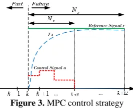
output and U is input signal. The term UT RU it may produce steady-state error at transient condition in the cost function J. Therefore, UT RU is replaced by (u-uss)T R(u-uss) where “ss” subscript is defined as steady-state value of the U signal. Since in the reference model Uss is kept at zero value therefore there will no steady state error in the output transient response. In addition, the desired output signal yd is achieved by applying a low pass filter with α order to the input signal is expressed in Equation (12). In this paper the low pass filter order is selected as α=0.83 and the respective forecast horizons of the motor and control system are considered 12 and 3, respectively.
(t 1) y (t i 1) (1 ) r(t i)
d d
y (12)
The “i” subscript is iteration number. The motor control strategy based on MPC is illustrated in Figure 3
4. SIMULATION AND EXPERIMENTAL RESULTS Nominal param eters of the test motor is provided in Table 1. The controller parameters of model reference is calculated in Equation (13). The reference position signal is a square waveform which is stepped from -3 to 3 radian with frequency of 0.333 Hz.
The controller parameters of model reference is calculated in Equation (13). The reference position signal is a square waveform which is stepped from -3 to 3 radian with frequency of 0.333 Hz.
(13)
2
1 2 2
2
1, 0.01 , 1.66
27 9 0.09
i i oi
oi oi
JK kgm
K T s K
T s
K T s
According to the Table 1 information, the load is modeled as moment of inertia which is added to the machine moment in Equation (5) where J=Jm+JL. Simulation results of PMSM rotor position using cascade controller, reference model controller and MPC
Control Signal u
Reference Signal r
... ...
Figure 3. MPC control strategy
TABLE1: PMSM and drive parameters
Parameter Value Parameter Value
Vdc 311V poles 4
Rs 8.5 Jm (motor moment) 0.001Kgm2
Ld 35mH JL (load moment) 0.0036Kgm2
Lq 66 mH Switching frequency 20 kHz
ψpm 0.09 wb Motor current 4.4 A
is illustrated in Figure 4. Simulation results demonstrate that the MPC has faster transient response in compare with the other techniques. According to the Figure 4 cascade structure time delay is 1 second for tracking the reference command. The reference model structure has reduced this time delay to 0.7 second and finally the MPC has reduced this time delay more i.e. 0.4 second with zero steady state error in counterclockwise dircetion. Durig suddenly change in the reference commad at time 1.5s and 3s from 3 to -3 radian and vice versa the MPC has a good tracknig ability incompare with the other casecade and reference model with lowest time delay. The motor speed in MPC has higher overshoot in compare with the other techniques which is illustrated in figure 5 due to the producing the higher current (higher torque) than others for obtaining the faster transient response.
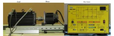
Consequently MPC has a good transeint behavier and tracking ability related to the casecade and reference model. For verification of MPC results due to simulation the implementation of MPC is done The experimental set up of motor-load and controllers is shown in Figure 6. For three-phase voltage source generation we used the three-phase inverter which is controlled by DSP hardware eZdsp F2812. The switching frequency of the system is adjusted to 20 kHz and the band-width of current controller is 2 kHz. Speed measurement is done by a 2048 pulse encoder with three Hall-effect sensors.
For protection of three phase inverter the q axis current is limited to the range of ̶ 10A ≤iqmax≤ 10A. For better and optimize control of PMSM the d axis current is set to zero and q axis current is set to 1 A.
using absolute difference between simulation and experimental values divided by experimental values in one period. This error value demonstrates that simulation and measured position is very close together during a transient command variation due to the suitable selection of feed-forward signals and well tuninig of controller coefficients. Figure 8 illustrates the speed of PMSM during position control process that it shows a good agreement between simulation and experimental results with 2.2% error.
The error of position and speed show that the proposed MPC combined with cascade structure is verified by experimental results. Finally Figure 9 shows the variation of q-axis stator current using simulation and measured values during the position control of PMSM.
0 0.5 1 1.5 2 2.5 3 3.5 4 4.5
-3 -2 -1 0 1 2 3
Time[s]
O
ut
p
ut
P
os
it
ion[
rad
]
Cascade Method Model Reference MPC Model Reference
Figure 4. PMSM position control using cascade structure, model reference and MPC
0 0.5 1 1.5 2 2.5 3 3.5 4 4.5
-40 -20 0 20 40
Time[s]
O
ut
p
ut
Sp
ee
d
(
rad
/s
)
Cascade Method Model Reference MPC Model Reference
Figure 5. PMSM speed variation using cascade structure, model reference and MPC
Figure 6. experimental set up of PMSM position control
0 0.5 1 1.5 2 2.5 3 3.5 4 4.5
-15 -10 -5 0 5 10 15
Time[s]
O
ut
p
ut
C
ur
re
nt
[A
]
Simulation Experimental
Figure 7. PMSM position using MPC (simulation and measured)
0 0.5 1 1.5 2 2.5 3 3.5 4 4.5
-40 -20 0 20 40
Time[s]
O
ut
p
ut
Sp
ee
d
[r
ad
/s
]
Simulation Result Experimental Result
Figure 8. PMSM speed using MPC (simulation and measured)
0 0.5 1 1.5 2 2.5 3 3.5 4 4.5
-15 -10 -5 0 5 10 15
Time[s]
O
ut
p
ut
C
ur
re
nt
[A
]
Simulation Experimental
Figure 9. q-axis current using MPC (simulation and measured)
It demonstrate the q-axis current using simulation result has a good agreement with experimental results. Therefore combination of MPC and cascade structure in position control of PMSM was successful.
5. CONCLUSION
In this paper model reference control method with combination of model predictive control is proposed in order to achieve a faster transient response with suitable error. This idea lead obtaining the fast transient response with appropriate steady state error related to the cascade structure and reference model methods. The simulation results of model predictive control compared with the cascade structure and reference model. Simulation results show the model predictive control has much better results contain faster transient response and good steady state error in compare with the others. Verification of simulation results carried out by experimental results very well.
6. ACKNOWLEDGEMENT
This research supported by electrical drive lab of Sharif University of technology. We are thankful to Dr. Tahami who provided expertise that greatly assisted the research.
7. REFERENCES
2. Kadjoudj, M., Benbouzid, M.E.H., Ghennai, C. and Diallo, D., "A robust hybrid current control for permanent-magnet synchronous motor drive", IEEE Transactions on Energy Conversion, Vol. 19, No. 1, (2004), 109-115.
3. Pilla, R., Tummala, A. and Chintala, M., "Tuning of extended kalman filter using self-adaptive differential evolution algorithm for sensorless permanent magnet synchronous motor drive",
International Journal of Engineering-Transactions B: Applications, Vol. 29, No. 11, (2016), 1565-1573.
4. Pukpinyo, C. and Assawinchaichote, W., "Ts fuzzy based h-infinity speed controller design for uncertain surface-mounted permanent-magnet synchronous motor", in Computer Science and Engineering Conference (ICSEC), 2016 International, IEEE., (2016), 1-6.
5. Suman, S.K., Gautam, M.K., Srivastava, R. and Giri, V.K., "Novel approach of speed control of pmsm drive using neural network controller", in Electrical, Electronics, and Optimization Techniques (ICEEOT), International Conference on, IEEE., (2016), 2780-2783.
6. Hsu, C.-J. and Lai, Y.-S., "Novel on-line optimal bandwidth search and auto tuning techniques for servo motor drives", in Energy Conversion Congress and Exposition (ECCE), 2016 IEEE, IEEE., (2016), 1-8.
7. Choi, S.-H., Ko, J.-S., Kim, I.-D., Park, J.-S. and Hong, S.-C., "Precise position control using a pmsm with a disturbance observer containing a system parameter compensator", IEE Proceedings-Electric Power Applications, Vol. 152, No. 6, (2005), 1573-1577.
8. Shyu, K.-K., Lai, C.-K., Tsai, Y.-W. and Yang, D.-I., "A newly robust controller design for the position control of permanent-magnet synchronous motor", IEEE Transactions on Industrial Electronics, Vol. 49, No. 3, (2002), 558-565.
9. Yu, H., Liu, X., Yu, J. and Song, Q., "Position tracking control of pmsm based on state error pch and mtpa principle", in Robotics, Automation and Mechatronics (RAM), 2011 IEEE Conference on, IEEE., (2011), 113-118.
10. Kumar, V., Gaur, P. and Mittal, A., "Ann based self tuned pid like adaptive controller design for high performance pmsm position control", Expert Systems with Applications, Vol. 41, No. 17, (2014), 7995-8002.
11. Jon, R., Wang, Z., Luo, C. and Jong, M., "Adaptive robust speed control based on recurrent elman neural network for sensorless pmsm servo drives", Neurocomputing, Vol. 227, (2017), 131-141.
12. Lin, C.H., "Adaptive recurrent chebyshev neural network control for pm synchronous motor servo‐drive electric scooter with v‐belt continuously variable transmission", International Journal of Adaptive Control and Signal Processing, Vol. 29, No. 7, (2015), 805-834.
13. Cortés, P., Kazmierkowski, M.P., Kennel, R., Quevedo, D.E. and Rodriguez, J.R., "Predictive control in power electronics and drives", IEEE Trans. Industrial Electronics, Vol. 55, No. 12, (2008), 4312-4324.
14. Clarke, D.W., Mohtadi, C. and Tuffs, P., "Generalized predictive control—part i. The basic algorithm", Automatica, Vol. 23, No. 2, (1987), 137-148.
15. Bolognani, S., Bolognani, S., Peretti, L. and Zigliotto, M., "Design and implementation of model predictive control for electrical motor drives", IEEE Transactions on Industrial Electronics, Vol. 56, No. 6, (2009), 1925-1936.
16. Abadi, A.G.R. and Hamidi, H., "Constrained model predictive control of low-power industrial gas turbine", International Journal of Engineering-Transactions B: Applications, Vol. 30, No. 2, (2017), 207-214.
17. Belda, K. and Vosmik, D., "Explicit generalized predictive algorithms for speed control of pmsm drives", in Industrial Electronics Society, IECON 2013-39th Annual Conference of the IEEE, IEEE., (2013), 2833-2838.
18. Cimini, G., Fossi, V., Ippoliti, G., Mencarelli, S., Orlando, G. and Pirro, M., "Model predictive control solution for permanent magnet synchronous motors", in Industrial Electronics Society, IECON 2013-39th Annual Conference of the IEEE, IEEE., (2013), 5824-5829.
19. Chai, S., Wang, L. and Rogers, E., "A cascade mpc control structure for a pmsm with speed ripple minimization", IEEE Transactions on Industrial Electronics, Vol. 60, No. 8, (2013), 2978-2987.
Position Control Improvement of Permanent Magnet Motor Using Model Predictive
Control
M. Arehpanahi, M. Fazli
Electrical Engineering Department, Tafresh University, Tafresh, Iran
P A P E R I N F O
Paper history:
Received 28 November 2017
Received in revised form 14 January 2018 Accepted 09 March 2018
Keywords: Position Control Permanent Magnet Motor Model Predictive Control Transient Response
A B S T R A C T
یراشبآ لرتنک موسرم راتخاس .تسا یکیرتکلا نیشام تیعقوم لرتنک متسیس کی زاین نیرتمهم ارذگ خساپ تقد و تعرس شهاک یارب ،هلاقم نیا رد .تسا یفیعض خساپ تعرس یاراد یلخاد یاه هقلح بسانمان دناب یانهپ ندوب اراد تلع هب هدافتسا اب عجرم لدم زا مئاد سیطانغم روتوم خساپ تعرس راتخاس نیا رد .تسا هدش هدافتسا روخ شیپ یاهلانگیس زا
شیپ یاهلانگیس نیا هلاقم نیا رد .دنوش یم دیلوت مئاد سیطانغم روتوم هدش هداس عجرم لدم هلیسوب روخ شیپ یاهلانگیس فتسا اب .تسا هدش بیکرت یراشبآ لرتنک راتخاس اب دنتسه نیب شیپ لرتنک یبیکرت شور هدافتسا دروم هک روخ نیا زا هدا
و یزاس هیبش جیاتن .تسا هدش نیمضت عجرم لانگیس ندرک لابند تیلباق زین و لااب تقد اب عیرس خساپ تعرس هدیا دنتشاذگ هحص هدش حرطم هدیا رب یهاگشیامزآ
.