Volume 01, No. 9, September 2015
P
age
19
Performance Improvement of Rectangular Patch Radiator Using
Spiral Metamaterial structure
Radhika Sharma* and Sachin Chalisgaonkar**
Department of Electronics, Maharana Pratap College of Engineering & Management, Gwalior, India
ABSTRACT:
This paper is aimed to investigate microstrip patch antenna loaded with metamaterial are
simulated for S-Band (1.70GHz-3.60GHz). Metamaterial offers advantages such as greater
bandwidth, reduction in return loss, impedance matching, high gain and high directivity.
FR-4 lossy material (dielectric constant εr = 4.3, height of substrate = 1.6mm and loss tangent =
0.02) is used for designing of patch antenna. Metamaterial is loaded on FR-4 substrate at
height of 3.314mm from ground plane. All simulations are carried by CST MW Studio
software. Single band rectangular microstrip patch antenna at frequency 2.33 GHz has been
simulated. Further metamaterial is loaded on a ground plane of rectangular microstrip patch
antenna at height 3.2mm, the return loss of antenna significantly decreasing form -30.5 dB to
-40.92 dB.
INTRODUCTION:
A microstrip patch antenna consists of a radiating patch on one side and ground plane on the other side with a dielectric substrate between them. A conventional microstrip antenna is shown in Fig. 1.1 Due to their advantages like low profile, light weight, low cost antennas etc they are getting much importance in various fields. In broadband areas the microstrip antennas are not still used since they have narrow-bandwidth, low gain, high loss etc. The patch is generally made up of conducting material such as copper or gold. The radiating patch and the feed lines are usually photo etched on the dielectric substrate.
Microstrip or patch antennas are becoming increasingly useful because they can be printed directly onto a circuit board. Microstrip antennas are becoming very widespread within the mobile phone market.
The patch is of length L, Width W and substrate of thickness h with permittivity
ɛ r. The thickness of the ground plane or of the microstrip is not critically
important. Typically the height h is much smaller than the wavelength of
operation, but not much smaller than 0.05 of a wavelength. The frequency of
operation of the patch antenna of Figure 1.1 is determined by the length L. The
Volume 01, No. 9, September 2015
P
age
20
r L
C f
2
Figure 1.1 Conventional microstrip patch antenna
A patch antenna is a narrowband, wide-beam antenna fabricated by etching the antenna element pattern in metal trace bonded to an insulating dielectric substrate, such as a printed circuit board, with a continuous metal layer bonded to the opposite side of the substrate which forms a ground plane. Common microstrip antenna shapes are square, rectangular, circular and elliptical, but any continuous shape is possible. Some patch antennas do not use a dielectric substrate and instead made of a metal patch mounted above a ground plane using dielectric spacers; the resulting structure has a wider bandwidth.
Because such antennas have a very low profile, are mechanically rugged and can be shaped to conform to the curving skin of a vehicle, they are often mounted on the exterior of aircraft and spacecraft, or are incorporated into mobile radio communications.
DESIGN AND ANALYSIS OF MICROSTRIP PATCH ANTENNA
Design Specifications:
The three essential parameters for the design of a Microstrip Patch Antenna are:
Frequency of operation (fo):
The resonant frequency selected for my design is 2.4 GHz.
Dielectric constant of the substrate (εr):
The dielectric material selected for my design is FR-4 lossy which has a dielectric constant of 4.4
Height of dielectric substrate (h):
The height of the dielectric substrate is selected as 1.6 mm.
The RMPA parameters are calculated from the formulas given below:
Width (w):
Volume 01, No. 9, September 2015
P age
21
equation to calculate width of Microstrip Antenna:
Length (L):
The length of microstrip filter depends on the effective permittivity of the substrate, the width and the desired resonant frequency.
The effective dielectric constant:
Calculation of Length Extension:
DESIGN-1
RECTANGULAR MICROSTRIP PATCH ANTENNA
Length of the patch antenna = 48 mm
Width of the patch antenna = 57 mm
Resonant frequency = 2.37 GHz
Figure 1.2: Simulated Rectangular Microstrip Patch Antenna
W h r r eff 12 1 1 . 2 1 2 1 ) 8 . 0 )( 258 . 0 ( ) 264 . 0 )( 3 . 0 ( 412 . 0 h w h w h L eff eff L f V L f L eff r eff r 2 2 2 2 1 0 0
0
Volume 01, No. 9, September 2015
P
age
22
Figure 1.3: Simulated return loss of proposed Antenna.
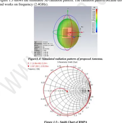
Figure 1.3 shows the simulated 3D radiation pattern. The radiation pattern became directional and works on frequency (2.4GHz).
Figure1.4: Simulated radiation pattern of proposed Antenna.
Volume 01, No. 9, September 2015
P
age
23
MICROSTRIP PATCH ANTENNA LOADED WITH SMM
In this paper characteristics of microstrip patch antennas on metamaterial substrates loaded with spiral shape structure known as spiral metamaterial (SMM). The proposed antenna utilizes SMM in the ground plane altering the effective medium parameters of the substrate. To characterize the performance of the SMM loaded microstrip antenna, themetamaterial substrate is modeled as an effective medium with extracted constitutive parameters. The Simulation results confirm that the SMM loaded patch antenna achieves size reduction and maintaining the same bandwidth as well. Metamaterials are finding numerous applications for novel antennas. One such application is the use of artif icial compact antennas. Miniaturization of microstrip antennas has different methods. Most popular way would be to use a high permittivity substrate decreasing the guided wavelength in the substrate, so the overall antenna size is reduced However, this approach has a drawback resulting in the tendency for more of the energy delivered to the antenna to be trapped in substrates with high permittivity, which decreases the antenna impedance bandwidth. To overcome the drawbacks of the patch antenna on a high permittivity substrate, several remedies have been proposed using artificial structures in conjunction with the patch element In this chapter, we propose a new design approach to the realization of compact antennas with improved impedance bandwidth using an artificial substrate based on Spiral shape and present the simulated and characteristics of the designed antenna. We investigate a microstrip patch antenna on a metamaterial substrate with Spiral shape employed in the ground plane, examine the resonant frequency, impedance bandwidth, and radiation characteristics using the effective medium approach.
The Rectangular microstrip patch antenna with metamaterial:
The RMPA with metamaterial has been designed with over all dimensions W (30mm) x L
(30mm). The designing of microstrip patch antenna, the resonant frequency fr= 2.4 GHz
and the dielectric substrate FR4 Lossy is used for simulation.
Volume 01, No. 9, September 2015
P
age
24
Figure 1.7: Simulated return loss of proposed Antenna
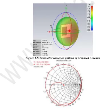
Figure 1.8 shows the simulated 3D radiation pattern. The radiation pattern became directional and works on frequency (2.4GHz).
Figure 1.8: Simulated radiation pattern of proposed Antenna
.
Volume 01, No. 9, September 2015
P
age
25
CONCLUDING REMARKS:
A compact microstrip antenna with an improved bandwidth using a spiral metamaterial substrate has been presented. For the characterization of the microstrip antennas on metamaterial substrates, the effective medium approach was employed. This new design help achieve the reduction of the antenna size and the improvement of the directivity for microstrip patch antennas.
On the basis of the simulated results it is observed that both antennas parameters has improved significantly by employing proposed metamaterial structure at 3.2 mm layer from the ground plane of the antenna. By using the metamaterial the return loss of conventional microstrip patch antenna is increased from -30.5dB to -40.92Db.
FUTURE SCOPE:
For enhancing the bandwidth and reducing the return loss of RMPA, metamaterial can be designed by using different substrate and structure. Antenna performance can also be analyzed by using different structure of patches and feeding techniques.
REFERENCES:
i. S. A. Schelkunoff, H.T.Friss, Antennas: Theory and Practice, New York: John Willy
& Sons, 1952.
ii. G. A. Deschamps, “ Microstrip Microwave Antennas”, presented at T hird USAF
symposium on Antennas, 1953.
iii. J. Brown, “Artificial dielectrics,” Progress in Dielectrics, vol. 2, pp. 195–225, 1960.
iv. Stutzman, W.L. and Thiele, G.A., Antenna Theory and Design, John Wiley & Sons
1998 . .
v. Y.T. Lo, Theory and experiment on microstrip antennas, IEEE Trans.AntennasPropag
27, pp.137–145. 1979
vi. J.S. Colburn and Y. Rahmat-Samii, patch antennas on externally perforated high
dielectric permittivity material, electron Lett. 31,pp.1710–1712. 1995
vii. C. A. Balanis, “Antenna Theory, Analysis and Design,” John Wiley & Sons, New
York, 1997.
viii. J. B. Pendry, A. J. Holden, D. J. Robbins, and W. J. Stewart, “Magnetism from
conductors and enhanced nonlinear phenomena,” IEEE Trans. Microw. Theory Tech. 47, pp. 2075-2081, 1999.
ix. R Garg, P Bhartia, I Bahl, and A. Lttipiboon, Microstrip antenna design handbook,
Artech House, 2000.
x. J. B. Pendry, “Negative Refraction Makes a Perfect Lens,” Phys. Rev. Lett.