IJE TRANSACTIONS B: Applications Vol. 31, No. 2, (February 2018) 339-345
Please cite this article as: H. Moradi CheshmehBeigi, Optimization and FEM Analysis of a Surface-mounted Permanent-magnet Brushless DC Motor,International Journal of Engineering (IJE),IJE TRANSACTIONS B: Applications Vol. 31, No. 2, (February 2018) 339-345
International Journal of Engineering
J o u r n a l H o m e p a g e : w w w . i j e . i rDesign, Optimization and FEM Analysis of a Surface-Mounted Permanent-magnet
Brushless DC Motor
H. Moradi Cheshmeh Beigi*
Electrical Engineering Department, Faculty of Engineering, Razi University, Kermanshah, Iran
P A P E R I N F O
Paper history:
Received 28 April 2017
Received in revised form 15 September 2017 Accepted 02 October 2017
Keywords:
Surface-mounted PM Brushless DC motor Finite Element Analysis
Analytical Model
A B S T R A C T
In this paper a fast analytical algorithm for design a surface-mounted PM Brushless DC motor (SMPM-BLDC) for variable-speed application based on electromagnetic field analysis and RSM optimization algorithm is discussed. To achieve the desired performance, the physical dimensions of the proposed SMPM-BLDC motor subject to minimal ripple torque utilizing RSM optimization algorithm were optimized. Finally, to evaluate the motor performance and confirm the accuracy of the proposed design procedure 2-D Finite Element (FE) analysis were employed. The obtained numerical analysis results explain the accuracy and effectiveness of the proposed machine design methodology.
doi: 10.5829/ije.2018.31.02b.19
NOMENCLATURE
Pout, Iphase Rated power output, Rated phase current hry, ℎ𝑡𝑠 The height of the rotor yoke, The stator tooth width,
Ephase Rated phase voltage Bst Maximum stator teeth flux density,
ωrated Rated speed hst, 𝐷𝑖 The stator slot height, The shaft diameter,
L, Dro Active motor length, Rotor outer diameter 𝐾𝑠 The slot packing factor,
hsy, T The height of the stator yoke, Motor developed torque 𝐷𝑦 The outer stator diameter,
Ncoil Number of coils conducting simultaneously 𝐴𝑠𝑙, 𝑙𝑓 The stator slot area, The lamination factor,
Nm, Nζ Number of pole, Number of slot/pole/phase 𝛷𝑡𝑚 The flux into this stator tooth,
kj The stacking factor of the stator iron laminations 𝐵𝑠𝑡 The stator tooth flux density,
Kw, Bg Winding factor, Specific magnetic loading 𝑓𝑓, 𝐴𝑠 The slot fill factor, The slot area,
Is, 𝑄𝑠 Specific slot loading, The number of stator slots, 𝜌𝑐 The resistivity of the wire at its operating temperature,
Bsy The maximum flux density in the stator yoke, 𝑙𝑐 The length of one turn of the winding coils,
ωs, tt Slot width, Tooth width 𝑙𝑒𝑥𝑡 The coil-end extension length and is a value generally between 10 and 30 𝑚𝑚,
𝐵𝑚 The flux density in the Air-Gap above the magnets, 𝜏𝑦, 𝛽 The coil pitch, The short pitch ratio,
lg The equivalent Air-Gap length 𝐼𝑎, 𝜌 The RMS phase current, The resistive of copper,
hm, Drc The magnet thickness, The rotor core diameter 𝜔𝑒𝑙𝑒𝑐 The electrical angular velocity,
𝑟 Stands for the radius at which the flux density is calculated 𝐴𝑠, 𝐴𝑐𝑜𝑛𝑑 The slot area, The conductor area,
𝛷𝑠𝑦 The maximum flux in the stator yoke, 𝑁𝑠 The number of slot,
Bsy, 𝛼 The stator yoke flux density, The half pole angle, 𝑁𝑤, Lst number of turns per phase, axial length of the motor,
hsy, Bry height of the stator yoke, Maximum rotor yoke flux
density Rr0, Bg
The air gap radius at the magnet surface, The air gap flux density,
lgand Ag The air gap length and cross-sectional area respectively, lmand Am The magnet length and cross-sectional area respectively,
INTRODUCTION
Variable-speed applications such as hybrid electric cars, aircraft and buses required fault-tolerance, high efficiency, low inertia, high torque/volume and maintenance free machine. The permanent-magnet brushless DC (PM BLDC) machine are popular for variable-speed applications due to their aspects. The PMBLDC machine inherently offers the advantages of high efficiency, high power density and maintenance-free operation. However, because of the uncontrollable PM electromagnetic flux, it suffers from a short constant-power operating range. To overcome this problem, the field-oriented flux-weakening control and the advanced conduction angle control were developed [1]. By improving the technology of high energy density PM materials not only reduces the size and the amount of losses, but also improves the efficiency of PMBLDC machines [2, 3].
A review on PMBLDC motors and control strategies with detailed aspects has been reported in literature [4]. Design, optimization, numerical analysis and torque capability study for BLDC motor is also discussed in literature [5, 6]. Yang et al. [7] have investigated design of a high-efficiency minimum-torque-ripple 12-V/1-kW 3-phase BLDC motor drive system for diesel engine has been studied. Also, design optimization of asymmetric air-gap structure for small 3-phase permanent magnet SPM BLDC motor were developed [8]. Jung et al [9] have studied on the effect of the magnetization direction on the iron loss characteristics in brushless DC motors. Qu et al. [10] have proposed an improved torque density and efficiency dual rotor, radial-flux BLDC motor. Comparisons of radial and axial field BLDC machines have been discussed by Sitapatiand Krishnan [11]. Another PM motor has been presented in literature [12-14]. Cheshmehbeigi and Khanmohamadian [12] have investigated on design and simulation of a
moving-magnet-type linear synchronous motor for
electromagnetic launch system. Multi-objective optimal design of a five-phase fault-tolerant axial flux PM motor has been discussed by Saavedra Ordóñez [13]. Vaez-Zadeh and Zamanian [14] have presented permanent magnet DC motor sliding mode control system.
The present paper approaches the design process based on fast analytic algorithm and FEM analysis for a three phase, salient pole PMBLDC for Variable-Speed application. In order to achieve the desired performance and aspects, the physical dimension of the PMBLDC motor should be minimized via utilization of RSM optimization algorithm. 2-D Finite element (FE) analysis was carried out to evaluate the motor performance and to confirm the accuracy of the proposed design procedure.
PROPOSED SMPM-BLDC MOTOR STRUCTURE and DESCRIPTION OF THE DESIGN ALGORITHM
The proposed BLDC motor in this paper is a surface-mounted PM synchronous motors which the PM are mounted on the outer surface of the rotor. Mounting the PM to the surface of the rotor is the cheapest and simplest method for construction of this group of electrical machines. An essential advantage of this specific design is yielding a rotor with small diameter and small inertia, which is suitable for fast dynamic application.
Design Process
Explaining the limitations and requirements of operation, is the first step of design process. The design specs, some constraints and target values are summarized in Table 1.
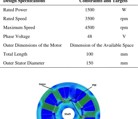
As shown in Figure 1, structure of the addressed machine in this paper is the 9/6 poles, surface-mounted PM type BLDC motor. The merit of this configuration is that all of the produced magnetic flux by the magnets links the stator and therefore takes part in energy conversion.
TABLE 1. The Constraints and Application Goals of the Design
Design Specifications Constraints and Targets
Rated Power 1500 W
Rated Speed 3500 rpm
Maximum Speed 4500 rpm
Phase Voltage 48 V
Outer Dimensions of the Motor Dimension of the Available Space
Total Length 100 mm
Outer Stator Diameter 150 mm
341 H. Moradi CheshmehBeigi / IJE TRANSACTIONS B: Applications Vol. 31, No. 2, (February 2018) 339-345
Figure 2. main dimension for proposed SMPM-BLDC motor
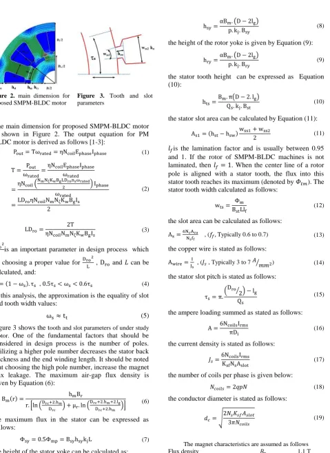
Figure 3. Tooth and slot parameters
The main dimension for proposed SMPM-BLDC motor is shown in Figure 2. The output equation for PM BLDC motor is derived as follows [1-3]:
Pout= Tωrated= ηNcoilEphaseIphase (1)
T = Pout
ωrated=
ηNcoilEphaseIphase ωrated
=ηNcoil(
NmNζKwBgLDronsωrated
2 ) Iphase
ωrated
=LDroηNcoilNmNζKwBgIs 2
(2)
LDro=
2T
ηNcoilNmNζKwBgIs (3)
Dro2
L is an important parameter in design process which by choosing a proper value for Dro
2
L , Dro and 𝐿 can be calculated, and:
tt= (1 − ωs). τs , 0.5τs< ωs< 0.6τs (4)
In this analysis, the approximation is the equality of slot and tooth width values:
ωs≈ tt (5)
Figure 3 shows the tooth and slot parameters of under study motor. One of the fundamental factors that should be considered in design process is the number of poles. Utilizing a higher pole number decreases the stator back thickness and the end winding length. It should be noted that choosing the high pole number, increase the magnet flux leakage. The maximum air-gap flux density is given by Equation (6):
Bm(r) =
hmBr
r. [ln (Drc+2.hm
Drc ) + μr. ln (
Drc+2.hm+2.lg
Drc+2.hm )]
(6)
the maximum flux in the stator can be expressed as follows:
Φsy= 0.5Φmp= BsyhsykjL (7)
the height of the stator yoke can be calculated as:
hsy=
αBm. (D − 2lg) p. kj. Bsy
(8)
the height of the rotor yoke is given by Equation (9):
hry=
αBm. (D − 2lg) p. kj. Bry
(9)
the stator tooth height can be expressed as Equation (10):
hts=
Bm. π(D − 2. lg) Qs. kj. Bst
(10)
the stator slot area can be calculated by Equation (11):
As1= (hst− hsw)
wss1+ wss2
2 (11)
𝑙𝑓is the lamination factor and is usually between 0.95 and 1. If the rotor of SMPM-BLDC machines is not laminated, then 𝑙𝑓 = 1. When the center line of a rotor pole is aligned with a stator tooth, the flux into this stator tooth reaches its maximum (denoted by 𝛷𝑡𝑚). The stator tooth width calculated as follows:
wts= Φm BstLlf
(12)
the slot area can be calculated as follows:
As=6NNcAcu
sff , (𝑓𝑓, Typically 0.6 to 0.7) (13)
the copper wire is stated as follows:
Awire= I
Js , (𝐽𝑠 , Typically 3 to 7
𝐴 𝑚𝑚2
⁄ ) (14)
the stator slot pitch is stated as follows:
τs= π. (Dro
2 ⁄ ) − lg
Qs
(15)
the ampere loading summed as stated as follows:
A =6NcoilsIrms πDi
(16)
the current density is stated as follows:
𝐽𝑠=
6NcoilsIrms KsfNsAslot
(17)
the number of coils per phase is given below:
𝑁𝑐𝑜𝑖𝑙𝑠= 2𝑞𝑝𝑁 (18)
the conductor diameter is stated as follows:
𝑑𝑐= √
2𝑁𝑠𝐾𝑠𝑓𝐴𝑠𝑙𝑜𝑡 3𝜋𝑁𝑐𝑜𝑖𝑙𝑠
(19)
The magnet characteristics are assumed as follows
Demagnetization flux density 𝐵𝐷 -0.2 T
Relative magnet permeability 𝜇𝑟 1.05
A reasonable design has the following flux densities Air-Gap flux density 𝐵𝑔 0.85 - 0.95 T
Maximum flux density in the
rotor yoke 𝐵𝑟𝑦 1.4 T
Maximum flux density in the
stator yoke 𝐵𝑠𝑦 1.4 T
Maximum flux density in the
stator teeth 𝐵 𝑠𝑡
1.8 T(near to saturation) • To prevent faced along with high temperatures and insulation, the maximum current density 𝐽𝑠 should be lower than 7 𝐴⁄𝑚𝑚2. This value is relevant for a motor without forced cooling. Depending on the way the motor is cooled, higher current densities could be achievable. The copper loss 𝑃𝑐𝑜𝑝 is given by 3𝐼2𝑅𝑐𝑢, where 𝑅𝑐𝑢 is the stator armature resistance per phase.
𝑅𝑑𝑐= 𝜌𝑐 𝑙𝑐𝑁𝑐
𝐴𝑐𝑢
(20)
𝑙𝑐= 2(𝐿 + 𝑙𝑒𝑛𝑑) (21)
𝑙𝑒𝑛𝑑= 2𝑙𝑒𝑥𝑡+ 𝜏𝑦 (22)
𝜏𝑦=
𝜋(𝐷 + 2(𝐻𝑠0+ 𝐻𝑠1) + H𝑠2)
𝑃 𝛽 (23)
the amplitude of the phase back-EMF is given by expression:
𝑒𝑝ℎ= 𝑁𝑤𝐷𝑠𝐼𝑎𝐵𝑔 𝜔𝑒𝑙𝑒𝑐
𝑝 (24)
and the electromagnetic torque is obtained as stated as follows:
𝑇 = 2𝑁𝑤𝐷𝑠𝐼𝑎𝐵𝑔 (25)
while the copper loss is given below:
𝑃𝑐𝑢= 2𝐼𝑎2𝜌 2𝑁𝑤𝐼𝑎
𝐴𝑐𝑜𝑛𝑑 = 24𝑁𝑤 2𝐼
𝑎2𝜌 𝐼𝑎 𝐴𝑠𝐾𝑠𝑁𝑠
(26)
where the cross-sectional area of the conductors is stated as follows:
𝐴𝑐𝑜𝑛𝑑= 𝐴𝑠
2𝐾𝑠 3𝑁𝑤
𝑁𝑠
(27)
TWO DIMENSIONAL FEM ANALYSES
Calculation of magnetic field characteristics for the machine parameters done accurately with FE techniques by applying precise machine geometry and materials properties. FEM has the ability to take into account the effects of magnetic field saturation based on machine performance. In this paper magnetic field analysis based on variational energy minimization technique (known as T-Ω formulation) was performed by employing Magnet
CAD package to determine the magnetic vector potential [15, 16].
∇. Τ − ∇. (∇Ω) = 0 (28)
{ ∇2T − μσ ( ∂T
∂t) = −μσ∇ ( ∂Ω
∂t) ∇2Ω = 0
(29)
𝑇 Electric vector potential, 𝛺 Magnetic scalar potential, 𝑇 𝑎𝑛𝑑 𝛺are defined by j = ∇ × T and H = T − ∇Ω The detailed derivation are discussed in literature [15]. In order to simplify the FE modeling problem a few assumptions have been made. To solve the problem with 2-D FEM analysis, the computed quantities were assumed to remain constant when considering different sections of the machine; also the materials of which the machine is made are considered to be isotropic. In this research for precise solution of Maxwell's equations and calculate the field analysis finite element technique is employed by utilizing a MagNet CAD package (Infolytica Corporation Ltd., 2007).
RESPONSE SURFACE METHOD (RSM) OPTIMIZATION ALGORITHM
RSM is a non-deterministic method for constructing global estimates to system behavior based on results calculated at different points in the design space. This method's advantage is in its reliable approximation for real experimental systems, which requires heavy computations, when sensitivity is not available and the batch run is impossible. But it is limited with errors caused by the nature of approximation [17, 18]. The most important sources of noise in designed BLDC motor are the ripple and cogging torque, which interacts between PMs and the stator teeth and cause vibration and speed perturbation. These undesirable effects cannot be reduced, unless an optimal PM shape is obtained through the optimization process.
In this paper, in order to reach to an acceptable result, RSM was used for the multi-quadric radial basis. The optimization technique has wide spread application in global interpolation, furthermore has the fitting ability when a limited number of experimental data is available. In first step, let's introduce the optimization algorithm. Response surface in a designed space can be modeled with following equations:
1
( ) ( )
N
i i
i
M x k l x x
(30)2 2 ( )
343 H. Moradi CheshmehBeigi / IJE TRANSACTIONS B: Applications Vol. 31, No. 2, (February 2018) 339-345
Where x is the design parameter vector,
i
kis the weight factor corresponding to the
i
th experimental data, l x( ) is the multi-quadric radial basis function, andc
is the shape parameter of the design. To determinek
i the weight factor, for a set of experimental data, one just have to solve the following equation:
(( , ( )),i i 1, 2,...,
X x j x i N Set of Given practical
data (32)
1
( ) ( ), 1, 2,...,
N
k i k i
i
j x k l x x k N
Determiningweight factor
(33)
As it is obvious, the shape parameter plays the most important role in fitting performance of RSM and its value is required to be chosen very carefully to have near-real approximations. Rippa [17] has utilized
1 0.815
N i i
d c
N
, where di is the distance between thei
thexperimental data and its nearest neighbor. It is also defined c 1.25D
N
, where D is the diameter of the
minimal circle enclosing all experimental data, and N is the number of achieved practical data [17]. Choices of these values are dependent to the nature of design procedure. The quality of the computed response surface (i.e., interpolation error) can be evaluated after choosing a value for shape parameter, by 'sequential leave one out' method, which is outlined briefly. After removing a solitary data ( , ( ))xk j xk from the original set
X, interpolation error can be defined as follows: 2
1
( ) N
k
k R R c
N
(34)( )
( ) ( ) k ( ), 1, 2,...,
k k k
R c j x M x k N (35)
Where newly constructed set of experimental data is
( )k
X and the corresponding error is ( )k
M .
But in the situation, where there are a fixed number of experimental data available, optimization occurs just through a good choice of shape parameter, because as mentioned it has the most vital effect on constructing the global response surfaces in algorithm introduced. Next step is adapting RSM with the designed BLDCM. After constructing the response surfaces, to obtain a minimal point, which is deeply dependent on the quantity of available experimental data, several different methods, which satisfy this aim can be used, but the most applicable one "(1+1) evolution strategy" was employed to produce the final results. While in stochastic observation, it was proved that increasing number of experimental data results in decreasing the corresponding interpolation error, but also it should be considered that to achieve a large number of points
when using the finite-element method, which lessens the error and produces result closer to real value, more computation time is required. For the designed BLDC motor, in regions where a large interpolation error is expected, in order to alleviate required computing time, additional experimental data was adaptively employed. Previously, Pan Seok Shin et al. [18] have conducted observation over shape optimization of large-scale BLDC motor. Interpolation error can be defined over the
kth
experimental data as the following equation:( ) ( )
( )
( ) ( )
abj k k
g k
abj k k
F x M x E x
F x M x
(36)
( ) abj
F x is the objective function, M x( ) is the response surface. Optimized response surfaces constructed both with original and additional data exhibit decreased corresponding error; thus, closer to real values. By repeating this process, adding adapted data in regions where a large error is expected, better response surfaces would be obtained.
NUMERICAL ANALYSIS RESULTS
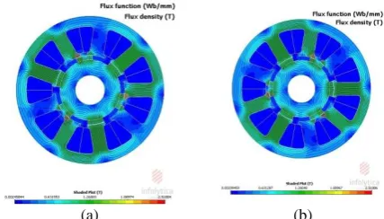
Complete model geometry, meshing, material properties and boundary conditions are pre-processing FEM analysis requirement. Figure 6 shows the no-load magnetic flux density for different rotor position (θ=0
oand 60o rotor position). The value of flux density in
different parts of the permanent magnet motor design is one of the important parameters. This parameter in core losses and the core saturation is very impressive.
In proposed structure an important design parameter is the air-gap flux density which has significant effect on the machine features. Therefore, this parameter must be chosen carefully. Figure 7 shows the air-gap flux density at no-load and the flux-current characteristics at different rotor positions.
Figure 8 shows distributed flux density at no load for different rotor position. The back EMF, cogging torque and the PM flux can be determined from the no-load field distribution.
(a) (b)
a- Air-Gap flux density at no-load
b- The flux-current character
Figure 7. The Air-Gap flux density at No-Load and the Flux-current characteristic
Figure 8 shown the induced line and phase Back-EMF waveforms in stator winding in rotor speed 𝜔𝑟. Cogging torque and torque profile of designed motor under 100% and 75% rated currents are presented in Figure 9. To achieve the required efficiency, the physical dimensions of the proposed structure is optimized in order to reduce torque ripple. For next step of design procedure, RSM optimization algorithm was employed subject to minimal ripple torque.
Figure 10 shown the results of optimized value for wts . Figure 10-a shown the influence of wts= 22°, 25° 𝑎𝑛𝑑 28° on the torque profile. The rotor pole Span has crucially effect on the 𝑇𝑎𝑣𝑒 and 𝑇𝑟𝑖𝑝, as it can be seen in Figure 10-b. The 𝑇𝑟𝑖𝑝 decreases with increasing wts. The 𝑇𝑎𝑣𝑒 can be increased by growing wts. Table 2 summarized specifications of the designed machine.
a- Phase Back-EMF waveform
b- Line and phase Back-EMF waveform
Figure 8. Line and phase Back-EMF waveforms
a- Cogging torque profile b- Torque-Rotor Position profile
Figure 9. Cogging torque and Torque profile of designed motor
a- Changing Rotor Pole width - Cogging Torque
b- Changing Rotor Pole width - TAve and TRip
Figure 10. Influence of changing rotor pole width a- Torque profile and b- Average Torque and Ripple Torque
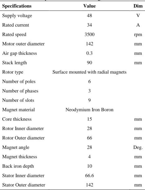
TABLE 2. Specifications of the designed machine
Specifications Value Dim
Supply voltage 48 V
Rated current 34 A
Rated speed 3500 rpm
Motor outer diameter 142 mm
Air gap thickness 0.3 mm
Stack length 90 mm
Rotor type Surface mounted with radial magnets
Number of poles 6
Number of phases 3
Number of slots 9
Magnet material Neodymium Iron Boron
Core thickness 15 mm
Rotor Inner diameter 28 mm
Rotor Outer diameter 66 mm
Magnet angle 28 Deg.
Magnet thickness 4 mm
Back iron depth 10 mm
Stator Inner diameter 66.6 mm
Stator Outer diameter 142 mm
CONCLUSION
345 H. Moradi CheshmehBeigi / IJE TRANSACTIONS B: Applications Vol. 31, No. 2, (February 2018) 339-345
REFERENCES
1. Hendershot, J.R. and Miller, T.J.E., "Design of brushless permanent-magnet machines, Motor Design Books, (2010). 2. Gieras, J.F., "Permanent magnet motor technology: Design and
applications, CRC press, (2002).
3. Hanselman, D.C., "Brushless permanent magnet motor design, The Writers' Collective, (2003).
4. Pillay, P. and Freere, P., "Literature survey of permanent magnet ac motors and drives", in Industry Applications Society Annual Meeting, 1989., Conference Record of the 1989 IEEE, (1989), 74-84.
5. Binns, K. and Shimmin, D., "The relationship between performance characteristics and size of permanent magnet motors", Proc. Elect. Drives Conf., (1995), 423–427.
6. Huang, S., Luo, J., Leonardi, F. and Lipo, T.A., "A general approach to sizing and power density equations for comparison of electrical machines", IEEE Transactions on Industry Applications, Vol. 34, No. 1, (1998), 92-97.
7. Yang, F., Jiang, C., Taylor, A., Bai, H., Kotrba, A., Yetkin, A. and Gundogan, A., "Design of a high-efficiency minimum-torque-ripple 12-v/1-kw three-phase bldc motor drive system for diesel engine emission reductions", IEEE Transactions on Vehicular Technology, Vol. 63, No. 7, (2014), 3107-3115. 8. Kam, S.-H. and Jung, T.-U., "A design optimization of
asymmetric air-gap structure for small 3-phase permanent magnet spm bldc motor", Journal of Magnetics, Vol. 20, No. 1, (2015), 91-96.
9. Jung, J.-W. and Kim, T.-H., "A study on the effect of the magnetization direction on the iron loss characteristics in brushless dc motors", Journal of Magnetics, Vol. 15, No. 1, (2010), 40-44.
10. Qu, R. and Lipo, T.A., "Dual-rotor, radial-flux, toroidally wound, permanent-magnet machines", IEEE Transactions on Industry Applications, Vol. 39, No. 6, (2003), 1665-1673. 11. Sitapati, K. and Krishnan, R., "Performance comparisons of
radial and axial field, permanent-magnet, brushless machines",
IEEE Transactions on Industry Applications, Vol. 37, No. 5, (2001), 1219-1226.
12. Cheshmehbeigi, H.M. and Khanmohamadian, A., "Design and simulation of a moving-magnet-type linear synchronous motor for electromagnetic launch system", International Journal of Engineering-Transactions C: Aspects, Vol. 30, No. 3, (2017), 351.
13. Saavedra Ordóñez, H., Riba Ruiz, J.-R. and Romeral Martínez, J.L., "Multi-objective optimal design of a five-phase fault-tolerant axial flux pm motor", Advances in Electrical and Computer Engineering, Vol. 15, No. 1, (2015), 69-76. 14. Vaez-Zadeh, S. and Zamanian, M., Permanent magnet dc motor
sliding mode control system, in Magnetic and superconducting materials: Volume 2. 2000, World Scientific.1081-1088. 15. Ren, Z., "T-/spl omega/formulation for eddy-current problems in
multiply connected regions", IEEE Transactions on Magnetics, Vol. 38, No. 2, (2002), 557-560.
16. Magnet, C., "Package: User manual", Infolytica Corporation Ltd., Montreal, Canada, Vol., No. 0.005, (2006), 0.01. 17. Rippa, S., "An algorithm for selecting a good value for the
parameter c in radial basis function interpolation", Advances in Computational Mathematics, Vol. 11, No. 2-3, (1999), 193-210.
18. Shin, P.S., Kim, H.-D., Chung, G.-B., Yoon, H.S., Park, G.-S. and Koh, C.S., "Shape optimization of a large-scale bldc motor using an adaptive rsm utilizing design sensitivity analysis",
IEEE Transactions on Magnetics, Vol. 43, No. 4, (2007), 1653-1656.
Design, Optimization and FEM Analysis of a Surface-Mounted Permanent-magnet
Brushless DC Motor
H. Moradi CheshmehBeigi
Electrical Engineering Department, Faculty of Engineering, Razi University, Kermanshah, Iran
P A P E R I N F O
Paper history:
Received 28April 2017
Received in revised form 15September 2017 Accepted 02October 2017
Keywords:
Surface-mounted PM Brushless DC motor Finite Element Analysis
Analytical Model
ديكچ ه
هرهب اب هلاقم نیا رد یارب کبوراج نودب میقتسم نایرج روتوم کی یزاس هنیهب و یحارط ،یلیلحت شور کی زا یریگ
لپیر شهاک فده عبات اب نیشام یکیزیف داعبا ،زاین دروم تاصخشم هب یبایتسد یارب .تسا هدش هیارا رییغتم تعرس یاهدربراک
اتشگ شور زا هدافتسا اب رو
RSM
هنیهب راتخاس ،هعلاطم دروم راتخاس ییاراک نداد ناشن یارب .تسا هدش یزاس
BLDC
هدش هسیاقم مئاد یابرنهآ نودب یلو هباشم راتخاس کی اب یداهنشیپ تقد و یداهنشیپ راتخاس ییاراک یبایزرا یارب اتیاهن .تسا
ود دودحم ناملا یددع زیلانآ شور یحارط هسورپ شور تقد یددع زیلانآ زا هدمآ تسدب جیاتن .تسا هدش هدافتسا یدعب
.دیامن یم قیدصت ار یداهنشیپ راتخاس یحارط