*Corresponding author: Rajiv Banerjee ISSN: 0976-3031
Research Article
DESIGN AND COMPARISON OF MULTISTORIED BUILDING OF R.C.C. SECTION AND
COMPOSITE SECTION BY STAAD.PRO V8i AND MANUAL
Mudit Kumar Verma., Syed Aqeel Ahmad., Anwar Ahmad and Rajiv Banerjee*
Department of Civil Engineering Integral University, Lucknow, India
DOI: http://dx.doi.org/10.24327/ijrsr.2018.0905.2116
ARTICLE INFO ABSTRACT
Composite construction, we discuss herein, is the combination of two materials viz. Reinforced concrete and structural steel used for the purpose of building yielding to behave together, increase safety and more economic without any damage to the aesthetic appearance. The deformation compatibility between two materials and the corresponding transfer of shear forces are maintained through friction or shear connectors. The composite structure is modelled in 3D form. While composite beam and column are moulded in beam elements, shear wall and slab are moulded as slab element. For high rise building, as being considered by us, the foundation is generally raft slab with under ream or driven piles. One more advantage in composite structure is its reduction of weight for the cause of reduced size of beam. E.g. - One can reduce the floor to floor height to 2.85m instead of 3.15m as in the case of R.C.C slab with conventional R.C.C. beam. Thus, a reduction of moment considerably.
INTRODUCTION
At present time, all major cities of India are becoming overcrowded with low rise buildings to shanties for residential purpose. City like Mumbai does not have horizontal space for expansion. In view of such a gloomy picturization of available space for future generation and an idea to this steps safe and secured give birth to composite building made of ductile steel encased in concrete. This kind of building materials makes the construction faster, easier and safer when subjected to lateral load. The methodology of composite building involves both steel and concrete and tie them together by using shear studs such that they can act together. Concrete carry compressive force and steel will carry tensile force. Let us elaborate with an example, if there a steel beam supporting concrete slab subjected to transverse load and there is mechanical connection between them and the bond stress between them is taken as zero, then both beam and slab will deflect and there is relative movement at the interface but the whole of the load will be taken by the steel beam. On the other hand, if there is mechanical bond between two elements to transfer the horizontal shear from slab to beam across the common interface so that the relative slope between slab and beam obviated and together the composite section will behave as
T-beam in which all or rest of the compression will be taken by concrete and all the tension will be taken by the steel. It is therefore imperative to say that the shear connector has the most important role to play in the composite section. The duty of shear connector is primarily to resist the horizontal movement between the concrete slab and steel beam and transfer horizontal shear. It is also necessary to restrain the slab which is under compression from lifting of the beam and it is for this reason connected to bar connector.
METHODOLOGY
Composite Design and Analysis: - Steel sections can take very high tensile force whereas under compression the functional behavior of buckling of steel section comes into play, which is always less than the tension carrying capacity of the section. In case of concrete, the material has such a less capacity in not considered in design. But concrete sections can take high value of compressive force. The methodology of composite design involves both concrete and steel and tie them together by using shear studs or some other anchorages so that they can act together as a composite section - concrete carrying mainly the compressive force and steel the tensile force. It helps the designer to design a section having lesser depth and thereby
Available Online at http://www.recentscientific.com
International Journal of
Recent Scientific
Research
International Journal of Recent Scientific Research
Vol. 9, Issue, 5(D), pp. 26755-26761, May, 2018
Copyright © Mudit Kumar Verma et al, 2018, this is an open-access article distributed under the terms of the Creative Commons Attribution License, which permits unrestricted use, distribution and reproduction in any medium, provided the original work is properly cited.
DOI: 10.24327/IJRSR
CODEN: IJRSFP (USA)
Article History:
Received 17th February, 2018
Received in revised form 12th
March, 2018
Accepted 04th April, 2018
Published online 28th May, 2018
Key Words:
Mudit Kumar Verma et al., Design and Comparison of Multistoried Building of
substantial saving in material cost is possible. The basic idea of designing a composite section is that the coefficient
expansion of both concrete and steel nearly same, which is also the basic for the development of RCC designs.
The following options have been considered in the design: (G+10) Composite, Brick Wall, Story Height 3.6 m (G+10) Steel, Brick Wall, Story Height 3.6 m
Steel concrete composite construction, structural steelwork is typically used together with concrete; for example, steel beams with concrete floor slab.
1. Relevant soil parameters 2. Wind speed
3. Terrain category and topography 4. Proximity of important structure
5. Earthquake zone and values of coefficients and acceleration spectra based on available local data from live site and stipulations of Bureau of Standards (BIS), British Standards and Euro Codes.
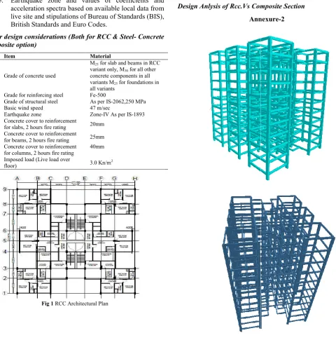
Other design considerations (Both for RCC & Steel composite option)
No. Item Material
1. Grade of concrete used
M25 for slab and beams in RCC variant only, M
concrete components in all variants M
all variants
2. Grade for reinforcing steel Fe-500
3. Grade of structural steel As per IS
4. Basic wind speed 47 m/sec
5. Earthquake zone Zone-IV As per IS
6. Concrete cover to reinforcement
for slabs, 2 hours fire rating 20mm
7. Concrete cover to reinforcement
for beams, 2 hours fire rating 25mm
8. Concrete cover to reinforcement
for columns, 2 hours fire rating
40mm
9. Imposed load (Live load over
floor) 3.0 Kn/m
Fig 1 RCC Architectural Plan
Design and Comparison of Multistoried Building of R.C.C. Section and Composite section by Staad.pro v8i and Manual
substantial saving in material cost is possible. The basic idea of designing a composite section is that the coefficient of thermal expansion of both concrete and steel nearly same, which is also the basic for the development of RCC designs.
The following options have been considered in the design: (G+10) Composite, Brick Wall, Story Height 3.6 m
Story Height 3.6 m
Steel concrete composite construction, structural steelwork is typically used together with concrete; for example, steel beams
Earthquake zone and values of coefficients and acceleration spectra based on available local data from live site and stipulations of Bureau of Standards (BIS),
RCC & Steel- Concrete
Material
for slab and beams in RCC variant only, M30 for all other concrete components in all variants M25 for foundations in all variants
As per IS-2062,250 MPa
IV As per IS-1893
3.0 Kn/m2
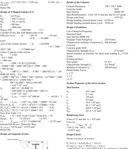
Fig 2 Steel Architectural Plan
Design Anlysis of Rcc.Vs Composite Section
Annexure
Section and Composite section by Staad.pro v8i and Manual
Steel Architectural Plan
Composite Section
International Journal of Recent Scientific Research
RCC Vs Composite
Design Analysis of RCC.Vs Composite Section
Annexure-2
Steel Vs Composite
Behaviour & Design Aspect of Composite Column
1. Composite column may be classified into two types 2. Open section partially or fully encased in concrete. 3. Concrete filled hollow steel section.
In composite construction, the base steel section support the initial steel section support the initial construction loads, including the weight of structure during construction. Concrete is later cast around the steel section, or filled hollow section, the steel provide a permanent formwork to concrete core. This allows, for example, the steel frame to be erected and the hollow column section subsequently to be filled with pumped concrete. This leads to appreciable savings in the time and cost of erection. In addition, the confinement provided by the closed steel section allows higher strength to be attained by concrete. Creep and shrinkage of concrete are also generally neglected in the design of concrete-filled tubes, which is not the case of
International Journal of Recent Scientific Research 'Vol. 9, Issue, 5(D), pp. 26755-26761, May, 2018
of RCC.Vs Composite Section
Composite Column
Composite column may be classified into two types partially or fully encased in concrete. Concrete filled hollow steel section.
In composite construction, the base steel section support the initial steel section support the initial construction loads, including the weight of structure during construction. Concrete is later cast around the steel section, or filled hollow section, e steel provide a permanent formwork to concrete core. This allows, for example, the steel frame to be erected and the hollow column section subsequently to be filled with pumped concrete. This leads to appreciable savings in the time and cost In addition, the confinement provided by the closed steel section allows higher strength to be attained by concrete. Creep and shrinkage of concrete are also generally neglected in filled tubes, which is not the case of
concrete encased sections. On the other hand, complete encasement of steel section usually provides enough fire protection to satisfy the most stringent requirement without restoring to other protection systems.
has the advantage of acting as
concrete is placed in two stages with the section. In order to ensure adequate force transfer between the steel and concrete it is sometimes necessary to use stud connector or reinforcement connected directly or indirectly to t
significant advantage of partially encased section is the fact that, after concreting some of the steel surfaces remains exposed and can be used for connection to other beams. Thus, concrete and steel are combined in such a fashio
advantage of both the materials are utilised effectively in composite column. Further, the lighter weight and higher strength of steel permit the use of smaller and lighter foundation. At present there is no Indian Standard covering composite columns. The method of design largely follows EC4 (1994), which incorporates the latest research on composite construction. Anyone of the following two methods can be used for calculation. The first is general method which takes explicit account of both second order effects and imperfections. This method in particular can be applied to columns of asymmetric cross-section as well as column whose section varies with height. The second is a simplified method which makes use of the European buckling curves for st
and explicitly takes account of imperfections. Here, simplified method is considered, because it is applicable to the majority of practical cases.
Calculation
Design of R.C.C Column (C1)
Considered grade of concrete Grade of reinforcement
Rectangular column to ground floor Pu = 475 ton
Mux = 18 t-m Muy = 1t-m
B = 400 mm
D = 800 mm
Assuming 28 mm dia. TMT bars d’/D = 40+14/800 = 0.0675 d’/B = 40+14/400 = 0.135 Pu/fck*BD = 475.5 * 10 Assumed Pt = 2% Hence, Pt/fck = 2/25 Pu2 = 19*10*40*80*10 -Pu/Pu2 = 475.5/608 From chart 43 of SP-16 Mux1 = 0.075 * 250 * 802 From chart 44 of SP-16
Muy1 = 0.07 * 250 * 80 * 40 = 22.4 ton-m
Mux/ Mux1 = 18/44.8 = .40178
Muy/ Muy1 = 1/22.4=0.0446 (As per chart 64 of IS 456)
Hence OK
Ast required – (2/100) * 40 * 80 Provide 12 nos. 28 dia. TMT bars.
26761, May, 2018
ased sections. On the other hand, complete encasement of steel section usually provides enough fire protection to satisfy the most stringent requirement without restoring to other protection systems. Partially encased section has the advantage of acting as the permanent formwork; the concrete is placed in two stages with the section. In order to ensure adequate force transfer between the steel and concrete it is sometimes necessary to use stud connector or reinforcement connected directly or indirectly to the metal profile. Another significant advantage of partially encased section is the fact that, after concreting some of the steel surfaces remains exposed and can be used for connection to other beams. Thus, concrete and steel are combined in such a fashion that the advantage of both the materials are utilised effectively in composite column. Further, the lighter weight and higher strength of steel permit the use of smaller and lighter At present there is no Indian Standard covering lumns. The method of design largely follows EC4 (1994), which incorporates the latest research on composite construction. Anyone of the following two methods can be used for calculation. The first is general method which takes nd order effects and imperfections. This method in particular can be applied to columns of section as well as column whose section varies with height. The second is a simplified method which makes use of the European buckling curves for steel columns, and explicitly takes account of imperfections. Here, simplified method is considered, because it is applicable to the majority of
Design of R.C.C Column (C1)
= M25
= Fe 415 Rectangular column to ground floor
Assuming 28 mm dia. TMT bars = 40+14/800 = 0.0675 = 40+14/400 = 0.135
= 475.5 * 103/(250*40*80) = 0594375 = 0.08
-3
= 608 ton = 0.782 2
* 40 * 10-5 = 44.8 ton-m = 0.07 * 250 * 80 * 402 * 10-5
= 1/22.4=0.0446 0.7
Mudit Kumar Verma et al., Design and Comparison of Multistoried Building of R.C.C. Section and Composite section by Staad.pro v8i and Manual
Ast provided – (12 * 615.752) = 73.89 cm2 (73.89 cm2 > 64 cm2)
Hence OK
Design of T-Shaped Column (C1)
Pu =2475 ton Mux = 949.77 ton-m Muy = 361.31 ton-m
B =300 mm
D = 2000 mm
Hence, D/B = 2000/300 = 6.7 Consider 28 dia. Bar with 40mm clear cover.
Effective cover = d’ = 40+14 = 54 mm
=d’/D = 54/2000 =
0.027
Area of the column section = Ag = (2D-B)B
= (2 * 2000 – 300) * 300 = 1110000 mm2
Centre of gravity of the section
X0 = 0.5D
= 0.5 * 2000 = 1000 mm
Y0 = (DB + D2-B2)/{2(2D-B)} = [2000 * 300 + 20002-3002]/[0.2 * 2000 – 300] = 609.46 mm
Ixx = DB2/12 + DB(Y0 - 0.5B)2 + [B(D-B)3]/12 + (D-B)B[{(D+B)/2} – Y0]2
= (2000 * 3003/12) + 2000 * 300 * (609.46 – 0.5*300)2 + [300 * (2000-300)3]/12 + (2000-300) *
300 * [[(2000 + 300)/2}-669.46]2 = 4.03 * 1011 mm4
Iyy = BD3/12 + (D-B)B3/12
= 300*20003/12 [(2000-300) * 3003]/12 = 2.04 * 1011 mm4
Zxx = Ixx/y0 = 4.03 * 1011/609.46 = 66124.1 * 104 mm3
Zyy = Iyy/x0 = 2.04 * 1011/1000 = 20400 * 104 mm3 Now, Pu/fck Ag = 2475 * 104/(35 * 1110000) = 0.64 Mux/fcuZxx= 949.77 * 107/(35 * 20400 * 104) = 0.41 Muy/fckZyy= 361.31 * 107/(35 * 20400 * 104) = 0.41 Now from Table 17.3
Py/fck = 75 + [(85-75)/(0.7-0.6)] * (0.64-0.6) = 79 Hence, Py= 79 *25/415 = 4.75%
i.e. As required = 4.75 * 1110000/100 = 52725 mm2 now,provide 86 nos. 28mm dia. Bars.
As provided = 52976 mm2> 52725 mm2 Hence OK
Design of Composite Section
Fig 2 Concrete Steel Composite
Details of the Columns
Column Dimension 350 * 350 * 3600
Concrete Grade M25
Steel Section ISHB 250
Steel Reinforcement 4 nos. Of 12 mm dia. Bar Fe 415 grade
Design axial load 4755 kN
Design bending moment about x-axis 62 kN-m Design bending moment about y-axis 10 kN-m
Design Calculations
List of Material Properties Structural Steel
Steel Section ISHB 250
Nominal Yield Strength fy 250 N/mm2 Characteristic modulus of elasticity Ea 200 kN/mm2 Concrete
Concrete grade M30
Characteristic Strength (fck)cu 25 N/mm2 Secant modulus of elasticity for short term loading Ecm 31220 N/mm
Reinforced Steel
Steel grade Fe 415
Characteristic Strength fck 415 Nmm2 Modulus of elasticity Es 200 kN/mm2 Partial Safety Factor
a 1.15
c 1.5
s1.15
Section Properties of the Given Section
Steel Section
Aa 6971 mm2
tf 9.7 mm
h 250 mm
tw 8.8 mm
Iax 79.8 * 106 mm2
Iay 20.1 * 106 mm4
Zpax 699.8 * 103mm3
Zpay 307.6 * 103 mm3
Reinforcing Steel
4 bars of 12 mm dia. As = 452 mm2 Concrete
Ac = Agross– Aa – As =350 X 350 – 6971 – 452 =115077 mm2
Design Checks
Plastic resistance of sections
Pp=Aafy/a + αcAc(fck)fcu/c + Asfsk/s Pp=Aafy/a + αcAc * .80 X fcy/c + Asfsk/s
= [6971*250/1.15 + .85*115077*25/1.5 + 452*415/1.15]/1000 = 3308.805 kN
Effective elastic flexural stiffness of the section for short term loading
About the major axis
International Journal of Recent Scientific Research 'Vol. 9, Issue, 5(D), pp. 26755-26761, May, 2018
= 452*[350/2-25-7]2 = 9.24*106 mm4
Icx =(3504/12-[79.8+9.24]*106
= 1161*106 mm4 {Ecd= Ecm/c =
31220/1.35=23125}
(EI)ex = 2.0*105*79.8*106 + 0.8*23125*1217.8*106 + 2.0*105*9.24*106
= 27.8 * 1012 Nmm
About minor axis
Similar to major axis.
Non-dimensional slenderness
l=(Ppu/Pcr)1/2 Value of Ppu:
Ppu = Aqfv+ αcAc(fck)cv + Asfsk Ppu = Aqfv+ αc*0.80*(fck)cv + Asfsk
= (6971*250 + .85*114913*25 + 415*452)/1000 = 4410 kN
(Pcr)x = ( )
l
= ∗ . ∗ = 21170 kN (Pcr)y = ∗ . ∗
= 19647.82kN
lx= (44.4/432.07)1/2 = .320
ly= (44.4/312.54)1/2 =.377
Check for the effect of long term loading
The effect of long term loading can be neglected if anyone or both of the following conditions are satisfied:
Eccentricity, e given by
e = M/P ≥ 2 times the cross-section dimension in the plane of bending considered.
ex = (180/1500)
= .012<2(.35)
ey =0
l< 0.8
Since condition (2) is satisfied, the influence of creep and shrinkage on the ultimate load needs not to be considered. Resistance of the composite column under axial compression Design against axial compression is satisfied if the following condition is satisfied:
P<Pp
Here,
P = 4755kN
Pp = 3308.805kN
and = reduction factor for column buckling.
values
About major axis
αx = 0.34
ϕx = 0.5[1 + .49(.377-.2) + (.377) 2
] = .572
x =1{1.1 + [{(0.572)2 - (0.326)2}1/2]
= 1.9
xPp> P
1.9 * 3308.805 = 6286.7295 kN> P (4755 kN)
The design is OK for axial compression.
About minor axis
Αy = 0.49
ϕy = 0.5[1 + .49(.377-.2) + (.377)2]
=0 .61
y =1{1.2 + [{(0.61)2 - (0.377)2}1/2]
= 1.8
yPp> P
1.8 * 3308.805 = 5955.93 kN> P (4755 kN)
The design is OK for axial compression.
Check for second order effect
Isolated non sway columns need not to be checked for second order effects if:
P/Pcr 0.1
4755/21170 = 0.22<0.1
Check for second order effect is not necessary.
Resistance of the composite column under axial compression and uniaxial bending
Compressive resistance of concrete Pc=AcPck = 1628 kN Plastic section modulus of the reinforcement
Zps = 4(/4*122)*(350-2-25-12/2) = 88*103 mm3
Plastic Section modulus of steel section Zpa = 699.8*10 mm3 (from steel table) Plastic Section modulus of the concrete Zpc = [bchc2/4]/Zpd-Zpa
= (350)3/4-88*103-699.8*103 = 9931*103 mm3
Check that the position of neutral axis is the web
= −
′(2 − )
2 + 2 2 −
= 114913 ∗
. 85 ∗ 25 1.5
2 ∗ 350 ∗. 85 ∗ 251.5 + 2 ∗ 8.8 2 ∗1.15250−0.85 ∗ 251.5
= 93.99 < ℎ
2− = 115.3
The neutral axis is in the web.
A’s = 0 as there is no reinforcement within the steel web
Section modulus about neutral axis
Zpsn = 0 (As there is no reinforcement within the region of 2hn from the middle line of the cross section)
Zpan = twhn2 = 8.8*(93.99)2 = 77740.3 mm3
Zpcn =bchn2-Zpsn-Zpan
= 350(93.99)2- 77740 = 3014.2*103mm3
Plastic moment resistance of section
Mp = py(Zpa-Zpan)+ 0.5*(Zpc-Zpen)+psk(Zps-Zpsn)
= 217.4(6998800-77740) +
0.5*0.85*25/0.5(9931000-3014200) + 361(88*1000)
= 216 kNm
Mudit Kumar Verma et al., Design and Comparison of Multistoried Building of R.C.C. Section and Composite section by Staad.pro v8i and Manual
The design against combined compression and uni-axial bending is adequate if following condition is satisfied
M 0.9Mp
M = 180kN
Mp = 216kN
= moment resistance ratio = 1-{(1-)d}/{(1-c)}
= 0.960
M = 0.9Mp = 0.9(0.960)*216 < 187 kN
RESULT
Equivalent Static Analysis
1. Equivalent static analysis is performed on both types of structure. Loads are calculated and distributed as per the code IS-1893-2002 and the results obtained are compared with respect to the following parameters. 2. Story stiffness: It can be observed that the transverse
and longitudinal story stiffness for composite structure is large as compared to rcc structure is about 12% to 15% more in transverse direction and about 6% to 10% more longitudinal direction than the RCC structure.
Comparison of Story Stiffness
Comparison of Storey Stiffness
Lateral Displacement: Displacement in composite structure is reduced by 41% to 58 % in transverse direction and about37% to 57% in longitudinal direction than that in RCC structure.
Comparison of Displacement
Comparison of Storey Drifts
Comparison of Storey Drifts
Comparison of Storey Drifts
0 50 100 150 200 250 300 Stor ey 1 Stor ey 2 Stor ey 3 Stor ey 4 Stor ey 5 Stor ey 6 Stor ey 7 Stor ey 8 Stor ey 9 Stor ey 10 Stor ey 11 St if fness () KN/m m Storey Stiffness Longitudinal RCC Composite
Comparison of Storey Stiffness
0 2000 4000 6000 8000 10000 12000 Stor ey 1 Stor ey 2 Stor ey 3 Stor ey 4 Stor ey 5 Stor ey 6 Stor ey 7 Stor ey 8 Stor ey 9 Stor ey 1 0 Stor ey 1 1 St if fness (KN /m m ) Storey Stiffness Transverse RCC Composite 0 5 10 15 20 25 Displace men t (m m) storey 0 RCC Composite 0 5 10 15 20 25 Stor ey 1 Stor ey 2 Stor ey 3 Stor ey 4 Stor ey 5 Stor ey 6 Stor ey 7 Stor ey 8 Stor ey 9 Stor ey 1 0 Stor ey 1 1 D ispla ce m ent (m m ) storey Displacement (Longitudinal) RCC Composite 0 2 4 6 8 10 12 Stor ey 1 Stor ey 2 Stor ey 3 Stor ey 4 Stor ey 5 Stor ey 6 Stor ey 7 Stor ey 8 Stor ey 9 Stor ey 1 0 Stor ey 1 1 Drif t( m m ) Storey
Storey Drift Transverse
RCC
International Journal of Recent Scientific Research 'Vol. 9, Issue, 5(D), pp. 26755-26761, May, 2018
Comparison of Storey Drift
RESULT
1. Thus we find that the use of modern technology like use of composite and the materials need to be used more and more to increase the safety of high rise building (since composite make the structure more ductile), reduction in cost of foundation, reduction in time of completion and use of water.
2. So on a conclude note, after analyzing the column (C1) as R.C.C. steel member, concrete steel composite, we found that concrete steel composite section exhibits excellent attributes in structural safety, design aspects and is also economical unlike others.
3. The dead weight of composite structure is found to be15% to 20% less than RCC structure and hence the seismic forces are reduced by 15 % to 20%.
4. It is observed that stiffness in composite structure is increased by 12% to 15% in transverse direction and about 6% to 10% in longitudinal direction as compared to reinforced concrete structure.
5. It is also observed that for composite structure the lateral displacements are reduced from 41% to 58% in transverse direction and about 37% to 57% in longitudinal direction than the RCC structure in linear static analysis and for linear static analysis it is reduced by 46% to 58% and 45% to 56% in transverse and longitudinal directions, respectively.
6. It is found that the lateral drift for composite structure is reduced by 35% to 50% and 27% to 38 % in transverse and longitudinal directions respectively in linear static analysis. In linear dynamic analysis the lateral drift is reduced by 42% to 50% and by 37% to 48% in transverse and longitudinal directions respectively than that of RCC structure.
7. The axial force in composite columns is found to be 20% to 30% less than RCC columns is found to be 20 to 30 % less than RCC columns in linear static analysis and in linear dynamic analysis it is found to be 18% to 30% less than RCC columns.
8. The shear force in composite columns is reduced by 28to 44 % and 24% to 40% in transverse to longitudinal directions respectively than the RCC structure I linear static analysis.
9. The twisting moment in composite columns is found to be 48% to 63% less and longitudinal directions respectively than reinforced concrete columns in linear static analysis and in case of linear dynamic analysis the twisting moment is reduced by 40% to 66% and about 39% to 65% in transverse and longitudinal directions respectively than the RCC structure.
10. The frequency of composite structure is increased by 10% to 17 % and time period decreased by 14% to 29% than the RCC structure.
11. The maximum negative bending moment in composite beam is found to be reduced by 16% to 32% in Equivalent static analysis and is also reduced by 11% to 18% in composite beams in.
References
1. Datta and S. Ghorai, “Multistoreyed Residential Building (B+G+20) Storied with Steel-Concrete Composite construction”, Institute for Steel Development & Growth; Publication No.: INS/PUB/117, 2010.
2. T.K. Bandyopadhyay, “Basic Concepts in Composite Structures”, Refresher Course on Composite Construction using Structural Steel, organized by Institute for Steel Development & Growth (INSDAG) and Jadavpur University, Kolkata, 2000.
3. nR. Narayanan, “Composite Steel Structures”, Advances, Design and Construction, Elsevier, Applied Science, UK, 1987.
4. Study Report, “Steel Framed Multistoried Buildings”, The Economics of Construction in the UK, CONSTRADO, (2), 1985,
5. R Narayanan, “Structural Steel Design”, Teaching Resource: Volume I, II &III: INSDAG Publication prepared by IIT Madras, Anna University and Structural Engineering Research Centre (SERC), Chennai.
6. D. Datta and A. Guha, “Guidebook for Design of Embossed Profiled Sheets acting as Composite Deck”, Institute for Steel Development & Growth; Publication No. INS/PUB/079, 2005.
7. D. Datta and S. Ghorai, “Multistoreyed Buildings with Steel-Concrete Composite Construction – (G+3) & (G+6)”, Institute for Steel Development & Growth; Publication No.: INS/PUB/132, 2013.
8. T.K. Bandyopadhyay, “Life-Cycle-Analysis of Steel-Intensive Green Buildings”, Green Engineering; Defining the Principles, Florida, USA, 2003.
9. D. Datta & S. Chanda, “Life Cycle Cost Analysis of Buildings”, Institute for Steel Development & Growth; Publication No. INS/PUB/129, 2012.
10. T.Sowmya and T.ValsaIpe “Experimental and Analytical Studies on Hat and U-Shaped Cold-Formed Steel Sections Subjected to Bending” Proceedings of the Sixth Structural Engineering Convention, SEC-2008 December 18-20, 2008, Chennai, pp.1301-1311.