COMPARATIVE STUDY ON ANALYSIS AND DESIGN
OF COMPOSITE STRUCTURE
Nitin m. Warade
1,
P. J. Salunke
2 1Department of Civil Engineering, PLITMS, Buldhana (India)
2
Department of Civil Engineering, MGM College of Engineering and Technology,
Kamothe, Navi Mumbai, (India)
ABSTRACT
This paper deals with the study of composite structure as compare with the concrete and steel structure. The
composite structure is far more advantageous over steel and concrete structure regarding Strength, Costs, and
Time Period requirements. There is no need for formwork because the steel beam is able to sustain the self
weight of steel and concrete, by itself or with the assistance of a few temporary props. Also this paperdeals with
the design of composite building with fixed base. In this paper seismic analysis of a multi level car park is made
using different construction material, like Concrete, Structural steel and Composite of Structural Steel and
Concrete. Effect of each building is studied with respect to time period, base shear, total dead load and most
important cost of different schemes.
Keywords: Composite Beam, Composite Column, Composite Action in Beam, Base Shear, Total
Dead Load, Cost.
I INTRODUCTION
The most important and most frequently encountered combination of construction materials is that of steel and
concrete, with applications in multi-storey commercial buildings and factories, as well as in bridges. These
materials can be used in mixed structural systems, for example concrete cores encircled by steel tubes, as well as
in composite structures where members consisting of steel and concrete act together compositely.
These essentially different materials are completely compatible and complementary to each other; they have
almost the same thermal expansion; they have an ideal combination of strengths with the concrete efficient in
compression and the steel in tension; concrete also gives corrosion protection and thermal insulation to the steel
at elevated temperatures and additionally can restrain slender steel sections from local or lateral-torsional
buckling. The purpose of this work is to introduce steel-concrete composite members and construction: to
introduction to composite building structure ;to describe the elements, the connections ,the fabrication and the
interaction of the elements ;and to discuss the structural systems used.
In multi-storey buildings, structural steelwork is typically used together with concrete; for example, steel beams
with concrete floor slabs. The extent to which the components or parts of a building structure should embody all
steel construction or constructed entirely in reinforced concrete or be of composite construction depends on the
circumstances. It is a fact, that engineers are increasingly designing composite and mixed building systems of
structural steel and reinforced concrete to produce more efficient structures when compared to designs using
either material alone.
It should be added that the combination of concrete cores, steel frame and composite floor construction has
become the standard construction method for multi-storey commercial buildings in several countries. Much
progress has been made, for example in Japan, where the structural steel/reinforced concrete frame is the
standard system for tall buildings. The main reason for this preference is that the sections and members shown
in image 1 are best suited to resist repeated earthquake loadings, which require a high amount of resistance and
ductility.
Fig1: The combination of concrete cores, steel frame and composite floor
In addition any structural system is usually subject to the following constraints. It should: conform to the
architectural requirements and those of the user or owner. Facilitate the service systems, such as heating,
ventilation and air conditioning, horizontal and vertical cabling, and other electrical and mechanical systems.
Facilitate simple and fast erection of the building, have adequate resistance to fire, enable the building,
foundation and ground to interact properly and most important be economical. Steel-concrete composite systems
for buildings are composed of concrete components that interact with structural steel components within the
same system. By their integral behavior, these components give the required attributes of strength, stiffness and
stability to the overall system. Composite members, as individual elements of systems, have been in use for a
considerable number of years. They consist of composite beams or trusses, encased or filled composite columns,
and steel deck reinforced composite slabs. These members are generally used in steel structures, and their
development as composite members is based on utilizing the concrete that would normally be required for floor
1.1.
Advantages of composite structure
Composite floor construction used for commercial and other multi-storey buildings, offers the following main
advantages to the designer and client;
Speed and simplicity of construction (metal decking, simple steel connections).
Lighter construction than a traditional concrete building (structural steel and lightweight concrete,
slender structural elements of small dimensions).
Less on site construction (steelwork, prefabricated structural elements).
Small (strict) tolerances achieved by using steel members manufactured under controlled factory
conditions to established quality procedures.
II. DESIGN CONSIDERATION FOR COMPOSITE FRAMED STRUCTURES
2.1. Building Components
Every building, whether it is large or small, must have a structural system capable of carrying all kinds of loads
- vertical, horizontal, temperature, etc. In principle, the entire resisting system of the building should be equally
active under all types of loading. In other words, the structure resisting horizontal loads should be able to resist
vertical loads as well and many individual elements should be common to both types of systems.
2.2 Floor Structures
Floor structures are responsible for a large percentage of the cost of buildings. They can be built using elements
of steel and reinforced concrete in various combinations. Structural floor systems are, of course, influenced by
the material used, but in all cases they are a combination of slabs and main or secondary beams. The
characteristic element, for the whole floor structure is the floor slab whose thickness and reinforcement is
dependent upon the span, the loading and the support conditions.
In floor construction, the use of the solid reinforced concrete slab is being replaced more and more by metal
decking see Figure 2. Modern profiled steel sheeting with additional indentations or embossments act as both
permanent formworks during concreting and tension reinforcement after the concrete has hardened.
At this final stage the composite slab consists of a profiled steel sheet and an upper concrete topping which are
interconnected in such a manner that horizontal shear forces can be resisted at the steel-concrete interface. Slip
(relative displacements) at the interface must be prevented completely or partly, so that vertical separation of the
steel decking from the concrete topping.The spanning capability of the construction can be extended by
increasing the slab depth but this increases the weight of construction and the depth of the floor beams. The
overall depth of the floor system is therefore determined by a balancing of factors. Experience has shown that
the most efficient floor arrangements are those using metal decking as permanent shuttering spanning 2.5 – 3.5
m between floor beams. For these spans the metal decking does not normally require propping during concreting
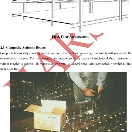
and the concrete thicknesses are near the practical minimum of 120 to 150 mm (Figure 3)
Fig 3. Floor Arrangement
2.3. Composite Action in Beams
Composite beams subject mainly to bending, consist of steel section acting compositely with one or two flanges
of reinforced concrete. The two materials are interconnected by means of mechanical shear connectors. It is
current practice to achieve this connection by means of headed studs semi-automatically welded to the steel
flange, see fig 4.
.
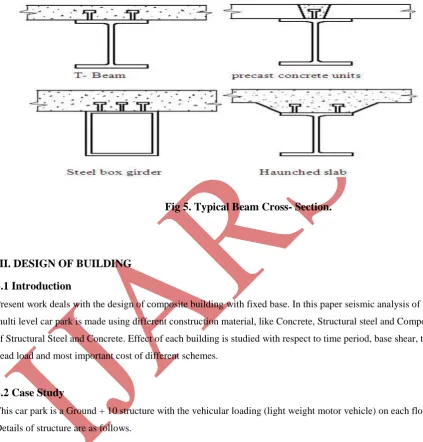
Figure 5. shows several composite beam cross-sections (rolled or welded sections) in which the wet concrete has
been cast in situ on timber shuttering. For single span beams, sagging bending moments due to applied vertical
loads cause tensile forces. in the steel section and compression in the concrete deck thereby making optimum
use of each material. Therefore composite beams even with small steel sections have high stiffness and can
carry heavy loads on long spans.
Fig 5. Typical Beam Cross- Section.
III. DESIGN OF BUILDING
3.1 Introduction
Present work deals with the design of composite building with fixed base. In this paper seismic analysis of a
multi level car park is made using different construction material, like Concrete, Structural steel and Composite
of Structural Steel and Concrete. Effect of each building is studied with respect to time period, base shear, total
dead load and most important cost of different schemes.
3.2 Case Study
This car park is a Ground + 10 structure with the vehicular loading (light weight motor vehicle) on each floor.
Details of structure are as follows.
Overall Dimension of Building- 54.0 m x 36.0 m.
Height of Building above Ground – 39.6 m.
Floor to Floor Height -3.6 m.
Purpose of Use- Parking Vehicles.
Ground and 1st Floor for Two –Wheeler Parking.
2 No’s of Car Lift and 2Nos Service Lift.
Ramp from Ground Floor to 1st Floor for Two-Wheelers.
Fig6. Typical Architectural Floor for Multilevel car park.
3.3 Analysis of Building
Analysis of the building is done as per Equivalent Static Procedure or Seismic coefficient Method. In this
method mass of structure is multiplied by design seismic coefficients, this force acts statically in horizontal
direction. It is also assumed that magnitude of coefficient is uniform for the entire member of the structure.
3.4 Modelling of Structure
The model is analysed using ETABS 9.0 to get more accurate and practical results. In total 15-models are made
5 each in RCC, Steel and Composite (G+6, G+7, G+8, G+9, G+10). The typical plan, location of beams,
location of columns, elevation and 3D of the model are Shown in Figures. All the models are compared w.r.t.
each other in terms of Time period, Total Base Shear, Total Dead Load, Total Cost of Building and Time
Duration Required for Execution.
3.5 Design of Building
The building is designed using respective code like IS 875 part-I, II 1997, IS456 2000, IS800 1998, IS11384
1998, Eurocode-I, II, III, IV for RCC, Steel and Composite Construction. The design of standard beam and
column using Composite behavior and steps given in Euro-Code is shown, but the permissible stresses are
considered according to IS Code. The slab is considered in pure RCC for the RCC and STEEL frame structure
are as for composite structure slab is with metal decking.
Dead Load of Slab for 150 mm thick – 0.15 X 25 = 3.75 KN/m2 (as per IS-875 Part -I)
Live Load – 5 KN/m2 (as per IS- 875 Part-II Table no.I)
3.5.2 Properties of Metal Decking Slab for Composite Structure
Fig8.
Comparison for Base Shear of the structure for different Heights of Building
STOREY G+6(26.7m) G+7(30.3m) G+8(33.9m) G+9(37.5m) G+10(41.4m)
RCC 10.53 11.86 13.19 14.52 15.86
STEEL 7.74 8.73 9.72 10.69 11.68
COMPOSITE 8.04 9.06 10.07 11.09 12.11
Fig7.
Comparison for Self weight of the structure for different Heights of the Building
STOREY G+6 (26.7m) G+7 (30.3m) G+8 (33.9m) G+9 (37.5m) G+10(41.4m)
RCC 0.250 0.253 0.256 0.259 0.260
STEEL 0.190 0.204 0.210 0.212 0.218
STOREY G+6(26.7m) G+7(30.3m) G+8(33.9m) G+9(37.5m) G+10(41.4m)
RCC 1.750 1.980 2.230 2.490 2.754
STEEL 1.540 1.680 1.830 2.000 2.160
COMPOSITE 1.570 1.820 2.090 2.364 2.640
RCC (IS-1893) 0.881 0.969 1.054 1.137 1.220
STEEL
(IS-1893) 0.998 1.098 1.194 1.288 1.380
Fig.9
Comparison for Time Period of the structure for different Heights of the Building.
STOREY G+6(26.7m) G+7(30.3m) G+8(33.9m) G+9(37.5m) G+10(41.4m)
RCC 6.70 7.5 8.46 9.35 10.24
STEEL 19.03 21.46 23.8 26.3 28.7
COMPOSITE 10.62 11.936 13.252 14.568 15.884
Fig.10
Comparison for Cost of the structure for different Heights of the Building
IV.CONCLUSION
This paper has outlined the necessity, concept, and favorable and unfavorable circumstances composite structure.
Composite construction, particularly that using profiled steel sheeting, allows rapid construction.
The weight of steelwork required in composite construction is significantly less than if the materials
were used independently.
There is no need for formwork because the steel beam is able to sustain the self weight of steel and
concrete, by itself or with the assistance of a few temporary props. Timber formwork can be replaced
by precast concrete elements or profiled steel sheeting.
Time period of building is decreased by 4% than normal R.C.C. building and 22 % increased than
STEEL building.
Completion period of the building came down by 21% when compared to R.C.C Structure and 23 % up
when compared to STEEL building.
Dead Load of building is decreased by 23 % than normal R.C.C. building and 3 % increased than
STEEL building.
Base Shear of building is decreased by 13 % than normal R.C.C. building and 3 % increased than
STEEL building.
As per this work the total cost of structure for composite is increased by 55% than normal R.C.C
building and 44% decreased than STEEL building.
V. ACKNOWLEDGEMENTS
Here I take this opportunity to thank all those who have directly or indirectly contributed in the successful
completion of this paper. I am thankful to Asst. Prof. P.J.SALUNKE for their valuable guidance and
encouragement throughout the completion of my work.
REFERENCES
Books:
[1] JONSON R.P., composite structures of Steel and Concrete; Volume 1: Beams, Columns, Frames and
Applications in Building. Granada. 1975.
[2] JONSON, R.P.,Composite Construction 1 and 2.
[3] LAWSON, R.M, Design of Composite Slabs and Beams with Steeel Decking, SCI-publication 055, 1989.
[4] LAWSON, R.M. and Rackham.J. , Design of haunched composite beams. The Steel Construction
Institute,1989.
[5] Hart,F., Henn,W., Sontag H., Multi-Storey Building in Steel .Second Edition, Collins, London 1985.
IS Codes:
[6] Eurocode 4: Design of composite steel and concrete structures:ENV 1994-1-1: part 1.1 : General rules and
rules for buildings.
[7] IS-3935-1996 Code of practice for Composite Construction.