Available Online at www.ijpret.com 158
INTERNATIONAL JOURNAL OF PURE AND
APPLIED RESEARCH IN ENGINEERING AND
TECHNOLOGY
A PATH FOR HORIZING YOUR INNOVATIVE WORK
WORKABILITY TEST ON REPLACEMENT OF FINE AGGREGATE BY WASTE
MATERIAL CERAMIC WASTE IN HIGH PERFORMANCE CONCRETE USING
STEEL FIBRE
ABHIJITSINH PARMAR1, JANMEJAY RAVAL2, HARSH SOHAGIA2, JIGAR DIXIT2 1. Assistant Professor, Department of Civil Engineering, SVBIT, Gandhinagar.
2. U.G. Student, Department of Civil Engineering, SVBIT, Gandhinagar
Accepted Date: 27/02/2016; Published Date: 01/03/2016
\
Abstract: - High strength Steel-fiber reinforced concrete is being used increasing day by day as a structural material. From many years High Performance Concrete has been used in column of high rise building [1]. High Performance Concrete (HPC) is a concrete meeting special combinations of performance and uniformity requirements that cannot be always achieved routinely by using conventional constituent sand normal mixing. Use of steel fiber in HPC is mainly for superior resistance to cracking and formation of cracks [2].In High performance concrete we are using ceramic waste as a waste material with 10%, 20%, 30%, and 40% replacement of fine aggregate. The aim of the present work will to use waste material as a replacement of fine aggregate in HPC using steel fiber . A series of workability tests will be conducted to study the effect of optimum replacement of fine aggregate by waste material (ceramic waste) and optimum use of steel fiber.
Keywords: High performance concrete, steel fibre, replacement, waste material, ceramic waste
Corresponding Author: MR. ABHIJITSINH PARMAR
Access Online On:
www.ijpret.com
How to Cite This Article:
Abhijitsinh Parmar, IJPRET, 2016; Volume 4 (7): 158-165
Available Online at www.ijpret.com 159
INTRODUCTION
ACI (American Concrete Institute) defines HPC as a specially engineered concrete, one or more specific characteristics of which have been enhanced through the selection of component materials and mix proportions.[5] Note that this definition does not cover a single product but a family of high-tech concrete products whose properties have been tailored to meet specific engineering needs, such as high workability, very-high early strength (e.g. 30-40 MPa compressive strength in 24 hours), high toughness, and high durability to exposure conditions.[6].There is some special Characteristics of HPC like Ease of placement, Compaction without segregation, Early age strength, Long-term strength and mechanical properties Permeability, Density, Heat of hydration, Toughness, Volume stability. There are major application of HPC is Pavements, Long-span bridges, High-rise buildings and other miscellaneous application are Floor slabs, Pavements, Refractories, Hydraulic structures, Thin shells, Rock slope stabilization, Mine tunnel linings, Many precast products etc.
MATERIALS USED
A. Cement:
The Ordinary Portland Cement of 53 grades conforming to IS: 8112 is being used.
Table – 1 Properties of Cement
PROPERTY IS CODE IS : 8112 - 1989
Specific Gravity 3.12
Consistency 33
Initial setting time 30 minimum
Final setting time 600 maximum
B. Fine aggregates:
Available Online at www.ijpret.com 160
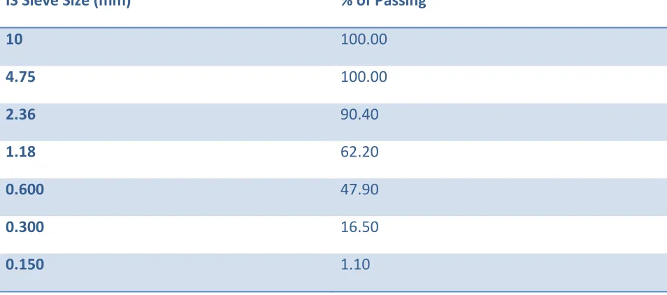
Table – 2 Sieve analysis of Fine aggregate
IS Sieve Size (mm) % of Passing
10 100.00
4.75 100.00
2.36 90.40
1.18 62.20
0.600 47.90
0.300 16.50
0.150 1.10
C. Coarse aggregates:
Coarse aggregates are particles greater than 4.75mm, but generally range between 10 mm to 40.5mm in diameter. They can either be from Primary or Secondary source.
D. Steel fibres:
Steel fibers of 50 mm length and 1 mm thickness with double hook end shape which gave an aspect ratio of 63.5 were used. The steel fiber was added by 3% of weight fraction.
E. Superplasticizer:
Glenium SKY 8784 helps to produce high performance concrete with longer workability
retention, and high early strength. Mostly compatible with all OPC, PPC, PSC and can be used with high pozzolonic material.
F. Ceramic waste:
Available Online at www.ijpret.com 161
PROCEDURE
The mix design was carried out for M55 grade concrete as per ACI: 363 which yielded a proportion of 1: 2.28: 1.55 with a w/c ratio of 0.33. The dosage of super plasticizer used was 0.79% (by weight of cement). The steel fibres were added at the rate of 2.0% by weight fraction. The cement, sand and coarse aggregates were weighed according to the proportion of 1: 2.28: 1.55 and dry mixed. The required amount of water was added to this dry mix and intimately mixed. The calculated quantity of super plasticizer was now added and mixed thoroughly. After this, steel 2% by weight of concrete material was added to the mix and the entire concrete was agitated thoroughly to get a homogeneous mix and workability test were carried.
METHODOLOGY
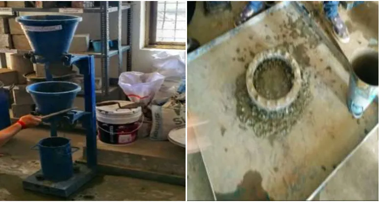
Fig – 1 (a) Compaction Factor Test (b) J-Ring Test
1) Slump Test:
As per IS:1199 (1959) Slump test is the most commonly used method of measuring consistency of concrete. It is not a suitable method for very wet or very dry concrete. The apparatus for conducting the slump test essentially consist of a metallic mould in the form of a frustum of a cone having the internal dimensions as under:
Slump Apparatus
Available Online at www.ijpret.com 162
Top diameter: - 10 cm
Height: - 30 cm
The internal surface of the mould shall be thoroughly cleaned and freed from superfluous moisture and any set concrete before commencing the test. The mould shall be placed on a smooth, horizontal, rigid and non-absorbent surface, such as a carefully levelled metal plate, the mould being firmly held in place while it is being filled. The mould shall be filled in four layers, each approximately one-q6arter of the height of the mould. Each layer shall be tamped with twenty-five strokes of the rounded end of the tamping rod. The strokes shall be distributed in a uniform manner over the cross-section of the mould and for the second and subsequent layers shall penetrate in@ the underlying layer. The bottom layer shall be tamped throughout its depth. After the top layer has been rodded, the concrete shall be struck off level with a trowel or the tamping rod, so that the mould is exact 19 filled. Any mortar which may have leaked out between the mould and the base plate shall be cleaned away. The mould shall be removed from the concrete immediately by raising it slowly and carefully in a vertical direction. This allows the concrete to subside and the slump shall be measured immediately by determining the difference between the height of the mould and that of the highest point of the specimen being tested. The above operations shall be carried out at a place free from vibration or shock, and within a period of two minutes after sampling.
2) Compacting Factor Test:
Available Online at www.ijpret.com 163 be refilled with concrete .from the same sample in layers approximately 5 cm deep, the layers being heavily rammed or preferably vibrated so as to obtain full compaction. The top surface of the fully compacted concrete shall be carefully struck off level with the top of the cylinder. The outside of the cylinder shall then be wiped clean.
The compacting factor =𝐖𝐞𝐢𝐠𝐡𝐭 𝐨𝐟 𝐩𝐚𝐫𝐭𝐢𝐚𝐥𝐥𝐲 𝐜𝐨𝐦𝐩𝐚𝐜𝐭𝐞𝐝 𝐜𝐨𝐧𝐜𝐫𝐞𝐭𝐞 𝐖𝐞𝐢𝐠𝐡𝐭 𝐨𝐟 𝐟𝐮𝐥𝐥𝐲 𝐜𝐨𝐦𝐩𝐚𝐜𝐭𝐞𝐝 𝐜𝐨𝐧𝐜𝐫𝐞𝐭𝐞
3) J Ring Test:
As per ASTM Perform the test on a flat, level, and nonabsorbent base plate. Position and shim the base plate so that it is fully supported and level. Pre-moisten base-plate with a damp towel, rag, or sponge. Rest the J-Ring at the center of the base plate. Filling Procedure B (Inverted Mold) – Dampen the mold, and place it on the base plate with the smaller opening facing down and concentric with the J-Ring. Support the mold and fill the mold in one lift (Note 2). Heap the concrete above the top of the mold. Strike off the surface of the concrete level with the top of the mold by a sawing motion of the strike off bar. Remove concrete from the area surrounding the mold to preclude interference with the movement of the flowing concrete. Raise the mold a distance of 9 ± 3 in (230 ± 75 mm) in 3 ± 1 s by a steady vertical lift with no lateral or torsional motion. Complete the entire procedure from start of the filling through removal of the mold without interruption within an elapsed time of 2½ min. Wait for the concrete to stop flowing and then measure the largest diameter (d1) of the resulting circular flow of concrete. When a halo is observed in the resulting circular flow of concrete, it shall be included as part of the diameter of the concrete. Measure a second diameter (d2) of the circular flow at approximately perpendicular to the first measured diameter (d1). Measure the diameters to the nearest ¼ in (5 mm). Determine the J-Ring flow in accordance with Section 9 of this test method. Conduct a slump flow test without the J-Ring in accordance with Test Method C 1611/ C 1611M. Use the same filling procedure as used with the J-Ring. Complete the tests with and without the J-Ring within 6 min.
TEST RESULTS
Available Online at www.ijpret.com 164
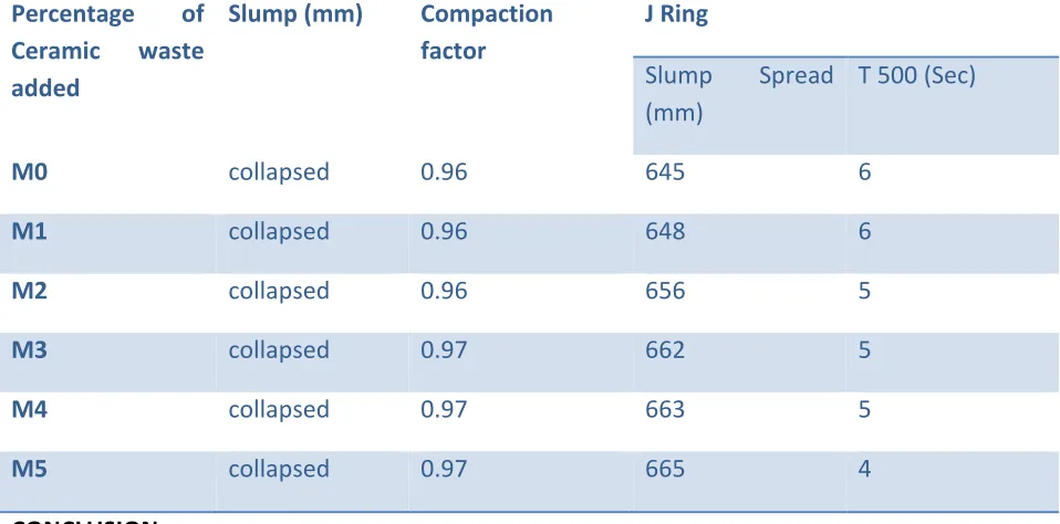
Table 4: Workability test results
Percentage of
Ceramic waste
added
Slump (mm) Compaction
factor
J Ring
Slump Spread (mm)
T 500 (Sec)
M0 collapsed 0.96 645 6
M1 collapsed 0.96 648 6
M2 collapsed 0.96 656 5
M3 collapsed 0.97 662 5
M4 collapsed 0.97 663 5
M5 collapsed 0.97 665 4
CONCLUSION
In this study ceramic waste were used as a replacement of Conventional fine aggregates. Replacement of Fine aggregates with Ceramic Waste will increase the workability of Concrete. Increase in the percentage of replacement of fine aggregate by fine ceramic waste will increase the workability of high performance concrete with steel fiber
REFERENCES
1. J. R. Del Viso, J. R. Carmona, G. Ruiz. Experimental study on the influence of the shape and
size of the specimen on Compressive behavior of High Strength Concrete.Experimental Analysis of Nano and Engineering Materials and Structures 2007. Pp 189- 190.
2. Khaloo AR, Kim N. Mechanical Properties of normal to high strength steel fiber- reinforced
concrete. Cement Concrete aggregates 1996; 18 (2): 92 7.
3. Tensing D,Jeminah and Jaygopal L S (2003) “ Permeability studies on steel fibre reinforced
concrete and influence of fly ash” National seminar on advance in construction materials,14-15 feb 2003.
4. Elavenil S. and Samuel Knight G.M (2007), “Behavior of steer fiber reinforced concrete
Available Online at www.ijpret.com 165
5. Ramadoss P. Studies on high-performance steel fiber reinforced concrete under static and
impa loads, Ph.D. Dissertation, Anna University-Chennai, Chennai, India, 2008.
6. A Sumathi, K. Saravana Raja Mohan, Strength Predictions of Admixed High Performance
Steel Fiber Concrete from International Journal of ChemTech Research, Oct-Nov2014.
7. Dr. Deepa A Sinha on study Workability Characteristic Properties of Concrete with Varying
Percentages of Steel Fibre Volume : 4 | Issue : 7 | July 2014
8. M. Adams Joe, A. Maria Rajesh, An Experimental Investigation on the Effect of GGBS & Steel
Fiber in High Performance Concrete from International Journal of Computational Engineering Research, Vol-04
9.
http://www.niir.org/projects/projects/rice-husk-rice-hull-rice-husk-ash-agricultural-waste-based-projects/z,,70,0,64/index.html
10. Balaguru P and Najm H, (2004), “High-performance fibre reinforced concrete mixture
proportion with high fibre volume fractions”Material Journal, 101(4), pp 281-286
11. http://www.ce.berkeley.edu/~paulmont/241/high_performance_concrete.pdf
12. Damgir R.M. and Ishaque M.I.M, (2003), “Effect of silica fume and steel fibre composite on
strength properties of high performance concrete” proceeding of the INCONTEST Coimbatore, pp 281-286
13. Robert C. Lweis and S. A. Hasbi, " Use of Silica Fume concrete selective case studies," The
Indian concrete Journal, October2001, vol.75 No. 10 pp. 645-652
14. ACI 363 – Guidelines for High Performance Concrete
15. Hitesh Kumar Mandavi, Vikas Srivastava, V.C. Agarwal on Durability of Concrete with