Organized by C.O.E.T, Akola. Available Online at www.ijpret.com
478
INTERNATIONAL JOURNAL OF PURE AND
APPLIED RESEARCH IN ENGINEERING AND
TECHNOLOGY
A PATH FOR HORIZING YOUR INNOVATIVE WORK
COMPARATIVE STUDY OF SEISMIC BEHAVIOUR OF RECTANGULAR COLUMNS
WITH CIRCULAR COLUMNS
SACHIN RAJENDRA INGLE
1, DR. ABHINANDAN R. GUPTA
21.M.E ( Struct. Engg), C.O.E.T, Akola, Maharashtra, India
2.Ph.D M.E ( Struct. Engg), MBA,M in ACM, C.O.E.T, Akola, Maharashtra, India
Accepted Date: 05/09/2017; Published Date: 10/10/2017
Abstract:
The earthquake resistant design of structures requires that structures should sustain, safely, any ground motions of an intensity that might occur during their construction or in their normal use. However ground motions are unique in the effects they have on structural responses. In this study the seismic behaviour of a frame building has been analysed by using software called as Staad. Pro. The seismic performance evaluation of the building has been carried out by changing the sizes of the columns and also by replacing the rectangular columns with the circular columns. The buildings are designed for the gravity and seismic loadings as per IS 456: 2000 and IS 1893: 2002.Keywords:
Rectangular columns , Circular columns, Base Shear, Displacment, Story Drift, Area of Steel, Shear Force, Axial Force, Bending Moment,Etc..
Corresponding Author: SACHIN RAJENDRA INGLE
Co Author: - DR. ABHINANDAN R. GUPTA
Access Online On:
www.ijpret.com
How to Cite This Article:
Sachin Rajendra Ingle, IJPRET, 2017; Volume 6 (2): 478-490
PAPER-QR CODE
SPECIAL ISSUE FOR
INTERNATIONAL LEVEL CONFERENCE
"ADVANCES IN SCIENCE,
Organized by C.O.E.T, Akola. Available Online at www.ijpret.com
479
INTRODUCTIONRC axially loaded members like columns or piles may have circular cross sectional shape due to architectural desire and/or structural requirements. Indeed, axially loaded members do not carry gravitational loads alone. But due to the seismic actions, lateral load components originate causing the generation of shear and flexural forces. In order to make structures safe against earthquakes these must be made ductile enough to withstand the lateral forces while some damage may be allowed. As the flexural design of RC circular members is following the same procedure as of the rectangular members, the detailed calculations for the circular cross section are a little bit of complexity. In this case we are going to study the behaviour of circular and rectangular column having same area under the effect of earthquake.
METHODOLOGY AND MODELING 2.1 GENERAL
The following basis has been considered for modelling of buildings.
1. The building will be used for residential purpose, as an apartment. So that there are walls inside the building. External walls 230 mm thick.
2. The main beams rest centrally on columns to avoid local eccentricity. 3. For all structural elements, M25 grade concrete will be used. 4. Sizes of all columns in all floors are kept the same.
5. The floor diaphragms are assumed to be semi rigid to have actual effect of floors slab.
6. Centre-line dimensions are followed for analysis and design.
7. Preliminary sizes of structural components are fixed by experience.
8. For analysis purpose, the beams are assumed to be rectangular so as to distribute Slightly larger moment in
columns.
9. Seismic loads will be considered acting in the horizontal direction (along either of the two principal directions) and not along the vertical direction, since it is not considered to be significant.
10. All dimensions are in mm, unless specified otherwise.
2.2 CASE CONSIDERATION
Problem for analysis of Rectangular and Square column on following data:
2.2.1 Modelling and analysis
The design parameters are as follows:
Live load : 25% of 3.0 KN/m2 at typical floor &
: 0.0 KN/m2 on terrace
Floor finish : 1.0 KN/m2
Earthquake load : As per IS-1893 (Part-I) - 2002
Type of soil : Type II, Medium as per IS: 1893
Story height : Typical floor 3.2 m.
Floors : G.F. + 09 upper floors.
Wall thickness : 230 mm thick brick masonry wall
Column size : 200 mm Diameter for Circular Column
Column size : 160X200 mm Diameter for Rectangular Column
Organized by C.O.E.T, Akola. Available Online at www.ijpret.com
480
2.2.2 Material Properties
i) Concrete
All components are modelled with concrete grade M25 unless specified in analysis. For Grade of concrete M 25
Ec = 5 000 fck N/mm2
= 5 000 fck MN/m2
= 25000 N/mm2 = 25000 MN/m2.
ii) Steel
HYSD bar of Fe 415 confirming to IS: 1786 is used throughout.
3. OBSERVATION AND REMARK:
Following are the observations obtained from analysis of Circular Column and Rectangular Column buildings
Base Shear comparison of various Shaped Building along X- Direction and Z- Direction.
Table: - 3.1 shows Base Shear comparison of various Shaped Building along X- Direction
Various cases Circular column Rectangular column
Value of Base Shear along X- Direction
3025 3024
Table: - 3.2 shows Base Shear comparison of various Shaped Building along Z- Direction
Various cases Circular column Rectangular column
Value of Base Shear along Z- Direction
2584 2583
Organized by C.O.E.T, Akola. Available Online at www.ijpret.com
481
Fig: 3.2 show Base Shear comparison of various Shaped Building along Z- Direction.Table: - 3.3 Story Shear summery for all the types of building along X direction.
Floor N0. Circular column Rectangular column
10 326.348 326.195
9 654.917 654.928
8 517.465 517.474
7 396.184 396.191
6 291.074 291.079
5 202.135 202.138
4 129.366 129.368
3 72.769 72.770
2 32.342 32.342
1 8.085 8.086
Table: - 3.4 Story Shear summery for all the types of building along Z direction.
Floor N0. Circular column Rectangular column
10 278.771 278.624
9 655.170 654.927
8 517.665 517.473
7 396.338 396.190
6 291.187 291.078
5 202.213 202.138
4 129.416 129.368
3 72.797 72.769
2 32.354 32.342
Organized by C.O.E.T, Akola. Available Online at www.ijpret.com
482
Fig.3.3: - Story shear along X directionFig.3.4: - Story shear along X direction
Table 3.5: - Corner Edge Displacement Value along X Direction considering all the cases for load combination 1.5(DL+ (X)).
Floor No. Circular column Rectangular column
10 2331.467 4945.642
9 2268.408 4774.94
8 2139.779 4470.929
7 1951.086 4054.948
6 1715.119 3552.531
5 1444.087 2986.408
4 1148.581 2375.985
3 837.438 1737.309
2 518.789 1084.71
Organized by C.O.E.T, Akola. Available Online at www.ijpret.com
483
Table 3.6: - Corner Edge Displacement Value along X Direction considering all the cases for load combination1.2(DL+LL+ (+X)).
Floor No. Circular column Rectangular column
10 1865.196 3956.52
9 1814.731 3819.956
8 1711.823 3576.743
7 1560.869 3243.958
6 1372.095 2842.025
5 1155.27 2389.126
4 918.864 1900.787
3 669.95 1389.847
2 415.039 867.768
1 166.335 355.35
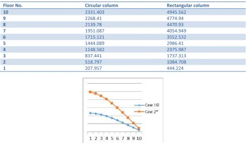
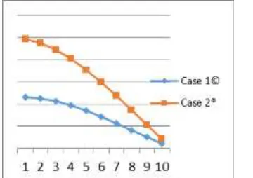
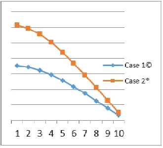
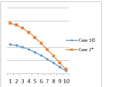
Table 3.7: - Corner Edge Displacement Value along X Direction is considering all the cases for load combination 0.9DL+1.5(+X).
Floor No. Circular column Rectangular column
10 2331.403 4945.562
9 2268.41 4774.94
8 2139.78 4470.93
7 1951.087 4054.949
6 1715.121 3552.532
5 1444.089 2986.41
4 1148.582 2375.987
3 837.441 1737.313
2 518.797 1084.708
1 207.957 444.224
Organized by C.O.E.T, Akola. Available Online at www.ijpret.com
484
Fig:3.6: - Shows Corner Edge Displacement Value along X Direction for load combination 1.2(DL+LL+ (+X)).Fig:3.7: - Shows Corner Edge Displacement Value along X Direction for load combination 0.9DL+1.5(+X).
Table 3.8: - Shows Corner Edge Displacement Value along Z Direction for load combination 1.5(DL+ (Z)).
Floor No. Circular column Rectangular column
10 2205.086 3848.858
9 2144.459 3710.261
8 2022.323 3470.674
7 1844.063 3143.816
6 1621.544 2749.026
5 1366.115 2304.012
4 1087.689 1824.086
3 794.569 1322.202
2 494.269 811.133
1 200.255 318.166
Table 3.9: - Shows Corner Edge Displacement Value along Z Direction for load combination 1.2(DL+LL+ (+Z))
Floor No. Circular column Rectangular column
10 1764.073 3079.092
9 1715.569 2968.21
8 1617.858 2776.539
7 1475.25 2515.053
6 1297.235 2199.221
Organized by C.O.E.T, Akola. Available Online at www.ijpret.com
485
4 870.151 1459.268
3 635.655 1057.761
2 395.415 648.907
1 160.202 254.53
Table 3.10: - Shows Corner Edge Displacement Value along Z Direction for load combination 0.9DL+1.5(+X).
Floor No. Circular column Rectangular column
10 2205.036 3848.804
9 2144.461 3710.264
8 2022.323 3470.674
7 1844.064 3143.817
6 1621.545 2749.027
5 1366.117 2304.013
4 1087.691 1824.087
3 794.572 1322.205
2 494.269 811.133
1 200.274 318.185
Fig:3.8: - Shows Corner Edge Displacement Value along Z Direction for load combination 1.5(DL+ (Z)).
Organized by C.O.E.T, Akola. Available Online at www.ijpret.com
486
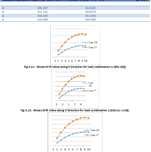
Fig:3.10: - Shows Corner Edge Displacement Value along Z Direction for load combination 0.9DL+1.5(+X).Table 3.11: - Story Drift Value along X Direction considering all the cases for load combination 1.5(DL+ (X)).
Floor No. Circular column Rectangular column
10
9 63.059 170.702
8 128.629 304.011
7 188.693 415.981
6 235.967 502.417
5 271.032 566.123
4 295.506 610.423
3 311.143 638.676
2 318.649 652.599
1 310.865 640.518
Table 3.12: - Story Drift Value along X Direction considering all the cases for load combination 1.2(DL+LL+(+X)).
Floor No. Circular column Rectangular column
10
9 50.465 136.564
8 102.908 243.213
7 150.954 332.785
6 188.774 401.933
5 216.825 452.899
4 236.406 488.339
3 248.914 510.94
2 254.911 522.079
1 248.704 512.418
Table 3.13: - Story Drift Value along X Direction considering all the cases for load combination 0.9DL+1.5(+X).
Floor No. Circular column Rectangular column
10
9 62.993 170.622
8 128.630 304.01
7 188.693 415.981
6 235.966 502.417
Organized by C.O.E.T, Akola. Available Online at www.ijpret.com
487
4 295.507 610.423
3 311.141 638.674
2 318.644 652.605
1 310.840 640.484
Fig:3.11:- Shows Drift Value along X Direction for load combination 1.5(DL+(X)).
Fig:3.12:- Shows Drift Value along X Direction for load combination 1.2(DL+LL+ (+X)).
Fig:3.13:- Shows Drift Value along X Direction for load combination 0.9DL+1.5(+X).
Table 3.14: - Story Drift Value along Z Direction considering all the cases for load combination 1.5(DL+ (Z)).
Floor No. Circular column Rectangular column
10
9 60.627 138.597
8 122.136 239.587
7 178.260 326.858
Organized by C.O.E.T, Akola. Available Online at www.ijpret.com
488
5 255.429 445.014
4 278.426 479.926
3 293.120 501.884
2 300.300 511.069
1 294.014 492.967
Table 3.15: - Story Drift Value along Z Direction considering all the cases for load combination 1.2(DL+LL+ (+Z)).
Floor No. Circular column Rectangular column
10
9 48.504 110.882
8 97.711 191.671
7 142.608 261.486
6 178.015 315.832
5 204.343 356.012
4 222.741 383.941
3 234.496 401.507
2 240.240 408.854
1 235.213 394.377
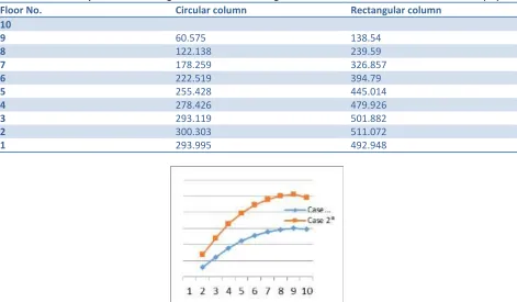
Table 3.16: - Story Drift Value along Z Direction considering all the cases for load combination 0.9DL+1.5(+Z).
Floor No. Circular column Rectangular column
10
9 60.575 138.54
8 122.138 239.59
7 178.259 326.857
6 222.519 394.79
5 255.428 445.014
4 278.426 479.926
3 293.119 501.882
2 300.303 511.072
1 293.995 492.948
Organized by C.O.E.T, Akola. Available Online at www.ijpret.com
489
Fig:3.15:- Shows Drift Value along Z Direction for load combination 1.2(DL+LL+ (+Z)).Fig:3.16:- Shows Drift Value along Z Direction for load combination 0.9DL+1.5(+Z).
4. CONCLUSION:
1. The analysis of the multi-storeyed building reflected that there is not much variation of base shear between the rectangular and circular building. Almost both the buildings have same base shear. This is due to the assumption of same dimensions for both buildings.
2. Corner Edge Displacement is found to be more in the rectangular columns than the frames having circular columns. Thus, the rectangular column building will perform better with less roof displacement as compared to circular column building with same amount of loading.
3. Story drift is found to be more in the rectangular columns than the frames having circular columns. Thus, the behaviour of rectangular column building is good as compared to circular column building.
4. From the above points discussed we can conclude that rectangular shaped columns give good performance against earthquake as compared to circular column, hence rectangular shaped columns should be preferred as compared to circular shaped columns in areas porn to high risk of earthquake.
5. REFERENCES:
1. S.L.Yunga, “Natural disaster, vol-1, Earthquake parameters including strong earthquakes.
2. Mizan Dogan, Earthquake education in civil engineering departments of universities of turkey, Europan journal
of educational studies 2(1), 2010
3. David vere Jones, Forecasting earthquakes and earthquake risks, International journal of forecasting, 11(1995)503-538.
4. G.H. Girty, Understanding Processes Behind Natural Disasters, ver. 1.0, June, 2009, Department of Geological
Sciences, San Diego State University.
5. Santosh Kumar Adhikari and Dr K. Rajasekhar,” Comparative Static and Dynamic Study on Seismic Analysis of
Organized by C.O.E.T, Akola. Available Online at www.ijpret.com
490
6. Thambisetty. Jaya Krishna and Mrs. B.Ajitha, Seismic Analysis of Lateral Systems in Tall Buildings for Different Soil Type and Seismic Zones, IJSRD - International Journal for Scientific Research & Development,Vol. 3, Issue 05, 2015.
7. E. Pavan Kumar1, A. Naresh2, M. Nagajyothi3, M. Rajasekhar4 “Earthquake Analysis of Multi Storied Residential
Building - A Case Study” ISSN: 2248-9622, Vol. 4, Issue 11(Version 1), November 2014, pp.59-64
8. Swapnil N. Dhande, Y. R. Suryawanshi, Praline S. Patil, Industrial Building Design on Seismic Issues, IJIRSET, Vol.4, Issue 5,2015.
9. K. Hari Prasad, P.Praveen Reddy, V. Satish kumar,B.Sandeep reddy hereby declare that the project report entitled “Analysis and design of multistory(G+6) residential building using Staad Pro”
10.K. Rama Raju*,1, M.I. Shereef3, Nagesh R Iyer2, S. Gopalakrishnan4 “analysis and design of rc tall building subjected to wind and earthquake loads” The Eighth Asia Pacific Conference on Wind Engineering, December 10– 14, 2013, Chennai, India
11. Verma Kapil; International Journal of Advance Research, Ideas and Innovations in Technology.
12.CĂTĂLIN MOGA, RALUCA NERIŞANU* and DELIA DRĂGAN
13.Indian Journal of Science and Technology, Vol 9(30), DOI: 10.17485/ijst/2016/v9i30/99230, August 2016