Comparative Study of Inner Core, Peripheral
and RC Shear Wall System
Raju K J Karthik Sampath
PG Student Assistant Professor
Department of Civil Engineering Department of Civil Engineering
Global Academy of Technology, Bengaluru - 560098 Global Academy of Technology, Bengaluru - 560098
Abstract
There has been a considerable increase in the construction of tall buildings both residential and commercial and the modern trend is towards more tall and slender structures. Thus, the effects of lateral loads like wind loads, earthquake loads and blast forces are attaining increasing importance. Shear wall system is one of the most commonly used lateral load resisting system in high rise buildings. Shear wall has high in plane stiffness and strength which can be used to simultaneously resist large horizontal loads and support gravity loads, which significantly reduces lateral sway of the building and thereby reduces damage to structure and its contents. When shear walls are situated in advantageous positions in the building, they can form an efficient lateral force resisting system by reducing lateral displacements under earthquake loads. Therefore, it is very necessary to determine effective, efficient and ideal location of shear wall.
Keywords: High-Rise Buildings, Lateral loads, Shear Wall System, efficient lateral force resisting system, Dynamic Loads _______________________________________________________________________________________________________
I. INTRODUCTION
Concrete walls made to resist lateral forces acting on the building is known as shear walls, these are vertical elements of the horizontal force resisting systems. Conventional RCC building resist lateral load up to an extent, but they do not resist as good as shear wall, various structural parameters exceed the limit and deform substantially when compared to shear wall. Whereas moderately designed shear wall will comparatively perform very well when compared to conventional RCC building in terms of resisting lateral load, gravity load etc. The cost to construct shear wall is also low when compared to the conventional RCC building, thickness of RCC shear wall should be in the range of 150mm-400mm. They deform substantially prior failure and hence provide a warning during failure. Hence shear wall is more economically than the conventional RCC building.
II. LITERATURE REVIEW
M PRIYANKA SONI: In this paper, A G+26 story structure of SMRF type is analyzed, here shear wall is located at 2 locations and the comparison of various structural parameters are compared for those shear walls the 2 shear walls positions are one is at the peripheral and one is at the internal when results are compared for these two differently located shear walls, the results conclude that the external shear walls reduce the various structural parameters are less for the external shear walls values are less for structural parameters when compared to internal shear walls, Hence it is finally concluded that shear walls at the peripheral give more stability to the building when compared to internal.
MEN JINJE: In this paper, a tall residential building with RC shear wall and with rectangular layout is presented. The parameter of constraints including story lateral stiffness, ratio of inter-story drift, seismic response force, and ratio of torsional period to translation period. Results are compared for each of following parameters. G+15 structure has been analyzed, seismic strengthening technology and the platform used to analyze is E-TABS.
O ESMAILI: In this paper, a 56-storey structure has been considered which is located in high seismic zones, in this tower shear wall system with irregular openings are utilized under both lateral, gravity and wind loads. Parameters considered are overall torsion, time dependent effects, construction sequence loading. Having concrete structure element with different longitudinal stiffness makes the tower to be more sensitive to differentiate displacement due to concrete time dependent and also the critical demands would be found to occur in the middle height of the structure.
M R SURESH: In this paper, study of optimum location of shear walls has been investigated with the help of different models. Main objective of this study is to determine parameters such as base shear, displacement and story drift of a G+20 structure, Platform used to analyze is E-TABS along four edges we can reduce story, story shear and also, we can increase strength and stiffness of the structure.
III. OBJECTIVES
Analyzing all the Structural Systems for Dynamic Analysis
To get several Structural Parameters of various Structural systems and obtain the corresponding Charts and graphs.
The following Structural Parameters are compared. Maximum Story Displacement. Maximum Story Drifts. Overturning Moments. Story Shears.
Also, to compare the charts to arrive to a conclusion on Stability among different Structural Systems.
IV. METHODOLOGY
Model Description:
The complete description of the methods followed in the modelling of the required buildings for the present work are stated. In the present work 3D models of three different types of structural systems are being modelled in seismic zone II to study
and compare the performance of the structures subjected to Earthquake forces of structures. Type of support for building is a fixed support.
All the models have same structural plan dimensions.
The grade of concrete considered for all columns is M50, for shear wall it is M40 and M30 for Slabs and Beams. The structure proposed for this project is a high-rise building of G+23 floors, used for residential building. The building is constructed using RC shear wall, Inner core and Peripheral shear wall.
Structural Data of the Building:
DETAILS DESCRIPTION
Site measurement 24.15x51.70m
Area 1248.56m2
No. of floors G+23
Height of each floor 2.9m
Height of the structure 69.6m
Grade of concrete
M30 for Beam and Slab M40 for Shear wall
M50 for Columns
Density of concrete 25kN/m3
Type of structure Inner core, Peripheral, RC Shear wall.
Thickness of slab 150mm
Thickness of shear wall 200mm
Beam geometrical dimensions 200x450mm and 200x650mm
Type of supports Fixed support
Seismic zone Zone II
Codes referred IS 456:2000, IS 1893:2002, IS 875, IS 13920
Parameters analysed Storey drift, lateral displacement, Base shear and Overturning Moment
Soil type Type II
Importance factor 1
Load combinations According IS 875-V
Terrain category for wind loads Category 3
Structure class for wind loads Class C
Material used Reinforced Cement Concrete
Reinforcement used HYSD Rebar
Purpose of Structure Residential use
Concrete Frame SMRF
Models:
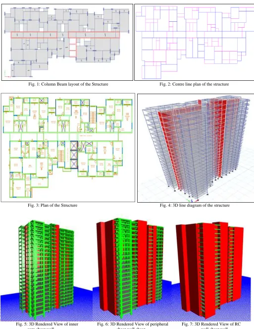
Fig. 1: Column Beam layout of the Structure Fig. 2: Centre line plan of the structure
Fig. 3: Plan of the Structure Fig. 4: 3D line diagram of the structure
Results of Analysis:
Structural parameter = Story shear
Type of structural system Base shear % increase
Inner Core 4712.99 -
Peripheral 4992.86 5.93
RC shear wall 5506.51 16.86
Story Shear values for case combo SPEC X for various Structural systems.
Fig. 8: Graphical representation of Story shear results for SPEC X of various Structural systems.
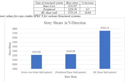
Type of structural system Base shear % increase
Inner Core 3213.95 -
Peripheral 3229.39 0.5
RC shear wall 3755.18 16.84
Story Shear values for case combo SPEC Y for various Structural systems.
Fig. 9: Graphical representation of Story shear results for SPEC Y of various Structural systems.
Structural Parameter = Maximum story displacement
Type of structural system Maximum Deflection (mm) % Reduction
Peripheral 9.431 -
Inner Core 5.242 44.41
Max. Story Displacement values for case combo SPEC X for various Structural systems.
Fig. 10: Graphical representation of Max. Story Displacement results for SPEC X of various Structural systems.
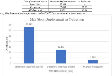
Type of structural system Maximum Deflection (mm) % Reduction
Inner Core 32.981 -
Peripheral 12.497 62.10
RC shear wall 2.985 90.94
Max. Story Displacement values for case combo SPEC Y for various Structural systems.
Fig. 11: Graphical representation of Max. Story Displacement results for SPEC Y of various Structural systems.
Structural Parameter = Maximum Story Drift
Type of structural system Drift % Reduction
Peripheral 0.000171 -
Inner Core 0.000093 45.61
Max. Story drift values for case combo SPEC X for various Structural systems.
Fig. 12: Graphical representation of Max. Story Drift results for SPEC X of various Structural systems.
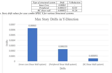
Type of structural system Drift % Reduction
Inner Core 0.00063 -
Peripheral 0.000233 63.01
RC shear wall 0.000055 91.26
Max. Story drift values for case combo SPEC Y for various Structural systems.
Fig. 13: Graphical representation of Max. Story Drift results for SPEC Y of various Structural systems.
Structural Parameter = Story Overturning Moment.
Type of structural system Overturning Moment (kN-m) % increase
Peripheral 12425.5421 -
Inner Core 15370.4756 23.70
Overturning Moment values for case combo SPEC X for various Structural systems.
Fig. 14: Graphical representation of Overturning Moment results for SPEC X of various Structural systems.
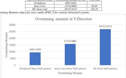
Type of structural system Overturning Moment (kN-m) % increase
Peripheral 9467.2039 -
Inner Core 15734.9882 66.20
RC shear wall 26715.9174 182.19
Overturning Moment values for case combo SPEC Y for various Structural systems.
Fig. 15: Graphical representation of Overturning Moment results for SPEC Y of various Structural systems.
V. CONCLUSION
In this present study, the comparison between hollow core shear wall, peripheral shear wall and RC Shear wall structural system were considered and were analyzed for different parameters for Dynamic loading, from the results the following conclusions can be drawn.
RC shear wall model analyzed for the dynamic analysis, comparatively performs well.
Overturning moment for the RC shear wall is higher, while the moment for the peripheral shear wall is lower.
RC shear wall values are less for the Story shear parameter, whereas Inner core shear wall values dominate the RC shear wall values in Y direction, and Peripheral shear wall does the same to RC shear wall in X direction.
Finally, it can be summarized that the variations in values is due to the type of structure and stiffness of the same, RC shear wall system performs well in all the considered structural parameters, because the entire structure is composed of RC wall where the stiffness, strength and load bearing capacity is homogeneous throughout the structure. Whereas for Peripheral shear wall and Inner core shear wall the stiffness, strength and load bearing capacity is heterogenous, that is to stay, in some parts they have excellent stiffness, strength and load bearing capacity and some parts do not. Hence it is evident by observing the variations in the values. Therefore, RC Shear wall is recommended and performs better when compared to Peripheral shear wall and inner core shear wall and it is the best for use in high tremor suspected areas.
REFERENCES
[1] Ms. Priyanka Soni1, Mr. Purushottam Lal Tamrakar, Vikky Kumhar, “Structural Analysis of Multistory Building of Different shear Walls Location and
Heights”, (IJETT) – Volume 32 Number 1- February 2016.
[2] Khushbu Jania, Paresh V. Pate, “Analysis and Design of Diagrid Structural System for High Rise Steel Buildings”.
[3] Varsha R. Harne, “Comparative Study of Strength of RC Shear Wall at Different Location on Multi-Storied Residential Building”, ISSN 2278-3652 Volume
5, Number 4 (2014).
[4] Haibei Xiong, Miguel Angel Hidalgo Calvo, “High-Rise Residential Reinforced Concrete Building Optimization”.
[5] Men Jinjie, Shi Qingxuan, He Zhijian, “Optimal Design of Tall Residential Building with RC Shear Wall and with Rectangular Layout”. International Journal
of High Rise Buildings Volume 3 Number 4.
[6] EsmailiS, Epackachi, M. Samadzad 3 and S.R. Mirghaderi, “Study of Structural RC Shear Wall System in a 56-Story RC Tall Building”, The 14th World
Conference on Earthquake Engineering October 12-17, 2008, Beijing, China.
[7] J. V. Sunil Ganesh, Mallikarjun S. Bhandiwad, “Seismic Analysis of Irregular Multistoried Structure with Shear Wall”, (ISSN 2321 – 919X).
[8] Er. Nishant Rana, SiddhantRana, “Structural Forms Systems for Tall Building Structures”, (SSRG-IJCE) – volume1issue4 September2014.
[9] Dr Sandeep Pingale, M. Pavani, G. Nagesh Kumar, “Shear Wall Analysis and Design Optimization in Case of High Rise Buildings Using Etabs (software)”,
ISSN Volume 6, Issue 1, January-2015.
[10] A.M. Pradhan, J.G. Bouwkamp, “Shear Walls in Hybrid construction for aseismic design”, ISBN 9054100605 1992Balkema, Rotterdam.
[11] JIANG Jun, YOU Bing, HU Ming, HAO Jiping, LI Yangcheng, “Seismic Design of a super High-Rise Hybrid Structure”, The 14th World Conference on