Channel Capacity Analysis of Spread Spectrum
Watermarking in Radio Frequency Signals
XU XIE1, (Member, IEEE), ZHENGGUANG XU2, AND HUI XIE1
1Naval University of Engineering, Wuhan 430033, China
2Huazhong University of Science and Technology, Wuhan 430074, China Corresponding author: Xu Xie ([email protected])
This work was supported in part by the Natural Science Foundation of China under Grant 61501195 and in part by the Naval University of Engineering under Grant HGDYDJJ13008.
ABSTRACT The carrier of the digital watermark expands from audio signals to radio frequency (RF) signals. Unlike audio signals, RF signals, such as the watermark transmission carrier, must be correctly demodulated with the watermark signals so that the distortion of the digital carrier embedded with the watermark is associated with the change in bit error rate. Based on the spread spectrum watermarking scheme, the distortion of the digital carrier signal is redefined, and the channel capacity expression of the watermarking scheme is derived. In addition, the optimal parameters to achieve the maximal channel capacity are discussed, and the constraint relation between the channel capacity and the allowable distortion is investigated.
INDEX TERMS Spread spectrum communication, demodulation, watermarking, channel capacity, distortion, bit error rate.
I. INTRODUCTION
Communication Authentication (CA) is an important aspect of security. Most authentication mechanisms (e.g., digital signatures and certificates) are above the physical layer and have an additional cost in bandwidth. In conventional digital communications systems, a sender uses a message signal to transmit message symbols to a receiver. The sender and receiver agree on a transmission scheme so that the mapping between signals and symbols is unique and known by both parties. The radio frequency (RF) watermarking extends the conventional communication system to concurrently transmit an additional authentication signal with the messages. The authentication signal is subject to the constraints of the mes-sage signal and can avoid using extra bandwidth. Unlike the traditional digital watermark, the carrier of the RF watermark is a radio frequency signal, so it is commonly called an RF carrier signal. The new scheme is authentication at the physical layer, where authentication is added to the signal by superimposing a carefully designed secret modulation on the waveform without requiring additional bandwidth. The physical layer identification can be used in both wired [1] and wireless channels [2].
A. PHYSICAL LAYER AUTHENTICATION
Applications using physical layer authentication have appeared in recent years. In [3], a transmitter identification
signal was added into the transmit signal from each transmit-ter in the Advanced Television Systems Committee (ATSC) terrestrial digital television (DTV) system. The injection level of the spread spectrum signal is significantly lower than the DTV signal, so the performance loss of the DTV signal is small. A watermarking technique is developed to embed cryptography encoded authorship signatures into data acquired by a wireless sensor network in [4]. The signature can be embedded into the data-sensing process or during data processing. The hidden information can be retrieved during extraction, and the original data are not required. An ID Modulation method to embed a bit-stream sensed in the RFID(Radio Frequency Identification) channel was proposed in [5] and used to authenticate sensor nodes. Watermarking to the physical layer of the wireless modulation waveform by Orthogonal Frequency Division Multiplexing (OFDM) was applied in [6], which can be used for copyright protection, distribution tracing, and authentication in wireless networks. In [7], the authentication information was embedded into the transmitted waveform by inserting an intentional frequency offset, which is a practically viable approach and notably robust to harsh channel conditions. In [8], the inherent redun-dancy in pulse shaping was used to embed the authentication signal into the message signal, which uses the controlled Inter Symbol Interference (ISI) to embed the authentication bits. In [9], the physical layer watermarking was added into
the direct sequence spread spectrum Signals, and only 2 dB extra signal-to-noise ratio (SNR) was required to maintain an acceptable packet error rate for one additional flipped chip. In [10], the Tikhonov-distributed artificial noise was introduced to interfere with the phase-modulated key to resist potential key-recovery attacks, which is also used in OFDM systems. In [11], the authors embedded watermark signals in duobinary modulation schemes. The watermarking information was embedded by designing the difference of bipolar codes of the initialization bit, which is required to begin the encoding of the carrier signal.
B. SPREAD SPECTRUM WATERMARKING
Although there are many schemes in the physical layer authentication, the most used RF watermarking scheme is spread spectrum watermarking, since the spread spectrum watermarking has been used in the ATSC Synchronization Standard for Distributed Transmission [12]. Spread spectrum watermarking is an important branch of the digital water-marking technology, whose core idea is hiding a watermark bit into carrier symbols to hide the watermark signal accord-ing to the theory of spread spectrum communication [13]. Most studies on spread spectrum watermarking focused on watermarking multimedia data and minimizing the distortion at the receiver in terms of human perception [14], [15]. The channel capacity of the spread spectrum in the RF signals remains lacking in research. Compared with the traditional digital watermark, the challenge is the distortion definition for the digital carrier signal. The traditional distortion def-inition is designed for analog signals, which measures the waveform changes, but the transmitted information in digital communication is the digital symbol. We are concerned about the BER of the digital symbol, not the waveform changes. Therefore, the distortion should be redefined, and the analysis conclusion is different from that of the available literature. This paper has two main contributions: the redefinition of the distortion for the RF watermark, which is different from the available definition for the multimedia watermark, and the expression of the channel capacity and optimal parameters to achieve the maximal channel capacity.
The present work has the following sections. Related works are discussed in Section II. Section III presents the model of the spread spectrum watermarking and the BER expression of the carrier symbol and watermark bit. The distortion of the carrier is redefined, and the channel capacity of the spread spectrum watermarking is analyzed in Section IV. Finally, the conclusions for this approach are drawn in Section V.
II. RELATED WORK
In the simplest spread spectrum watermarking scheme, the bits that compose the desired message are modulated by a spread spectrum sequence and added to the signal [16]. Since spread spectrum sequence is robust to interfering noise, the amount of energy (or distortion) that must be added to the watermarked signal to erase the watermark can be notably high. In fact, the signal is a source of
interference. In more elaborate schemes, differences in the signal may be explored to reduce subjective distortion intro-duced by the watermark [17], [18]. Since the RF carrier signal is generally much stronger than any interference that the signal must endure, the interference from the signal dominates the process. To eliminate the self-interference, an improved spread spectrum watermarking scheme is pro-posed by Malvar and Florêncio [19]. In this scheme, the information of the carrier is fully used to compensate for its interference to the watermark signal. The spread spec-trum watermarking scheme is also used in RF signals [20] for transmitter identification. However, embedding additional information in the RF signal usually degrades the original signal quality. Therefore, the watermarking model with side information is investigated [21], where the carrier is con-sidered a noise, but it can provide side information for the watermark embedding terminal to compensate for the self-interference. Hence, the embedding channel capacity is used to measure the performance of the watermarking scheme.
The theory of the embedding channel capacity was first investigated by Costa and is known as the dirty paper model [22]. Then, the method was used to analyze the channel capacity of the spread spectrum watermarking scheme [23], [24]. However, these works focused on the watermark in audio signals. Compared with traditional mul-timedia watermarking, the challenge is the distortion defi-nition for digital carrier signals. The traditional distortion definition was designed for analog signals, which measures the waveform changes. However, in digital communication, the transmitted information is based on the digital symbol. We are concerned about the BER of the digital symbol, not the waveform changes. Thus, the conclusions in [23] cannot be used for the RF signals. The experimental performance of the spread spectrum watermarking in RF signals is investigated in [25], and the authors show that the average performance loss of the conventional receiver because of the watermark signal is less than 0.2 dB when the watermark signal is injected at 30 dB below the original signal power. However, the theoretical channel capacity analysis for the spread spec-trum watermarking in RF signals remains absent.
In this paper, we attempt to analyze the watermark chan-nel capacity in RF signals. An important characteristic for the RF carrier is that the transmitted carrier must be accu-rately demodulated with the watermark bit, whereas the audio signal, as the watermark carrier, requires no demodulation. Therefore, the distortion definition of the RF carrier is notably different from that of the audio carrier. However, the dis-tortion for the RF carrier is not discussed in the available literature, so we investigate the distortion definition of the RF carrier after embedding the watermark. Then, the channel capacity expression is derived, and the optimal parameters for the maximal channel capacity are analyzed.
III. MODEL OF SPREAD SPECTRUM WATERMARKING To simplify the analysis, we do not consider the real fre-quency of the RF signal because the real frefre-quency does not
affect the conclusion in the additive white Gaussian channel. If we investigate the channel capacity in the fading channel, we should consider the effect of the real frequency because the signals with different frequencies have different fading characteristics. Now, we only consider the baseband model of the digital modulation. The digital signal is commonly used to transmit the exact information, so it should be correctly demodulated with the watermark signal at the receiving end. This is the key different characteristic between the digital carrier and the audio carrier.
For the binary digital baseband signal vector x, the ele-ments are xi = ±σx and satisfy the discrete uniform
dis-tribution. The pseudo random numbers u whose elements ui= ±σuare embedded into the host digital signal. Sequence
u is used as the spread spectrum sequence in the scheme, which is known in both sending and receiving ends and fixed in the communication process. If the length ofuis N, one watermark bit d is embedded into N carrier symbols. Therefore, the watermarked signal vectorswith lengthN is
s=x+du (1)
whered = ±1 is the value of the watermark bit. However, the information of the carrier can be used to change the water-mark embedding method. To explain the improved scheme in [19], we introduce the function of the normalized inner product (x,u)= 1 N N X i=1 xiui (2)
and the vector module is expressed as kuk =(u,u)= 1 N N X i=1 u2i. (3) To compensate for the interference of carrier, the embedding process in [19] can be expressed as
s=x+αdu−λxu=x+(αd−λx)u (4) and the watermark vector is
w=(αd−λx)u, (5) where
x=(x,u) /kuk (6) represents the correlation degree betweenxandu. Obviously, x is a Gaussian random variable with mean 0 and variance σ2
x/Nσu2, which is introduced to compensate for the carrier
interference. Parameters λ and α are used to control the compensation rate and watermarking embedding strength, respectively, and their ranges are both in the interval of [0,1]. Whenλ = 0 and α = 1, the watermarking scheme in (4) degenerates into the scheme in (1).
After being transmitted in the AWGN channel, the received vector is
y=x+(αd−λx)u+n. (7)
Since the carrier is the binary digital signal, we can decode the original carrier symbol by
ˆ xi= ( 1, yi≥0; −1, yi<0. (8) According to (7), the received vector can be rewritten as
y=x+αdu+v (9) where
v= −λxu+n
is the noise vector. Becausexis a Gaussian random variable with varianceσx2/Nσu2anduis known in the receiving end, the elements ofv are also Gaussian random variables with varianceσv2=λ2σx2/N+σn2.
Therefore, the probability density ofyiis expressed as
f (yi)= 1 √ 2πσv e− (yi−xi−αdui)2 2σ2 v . (10)
Whenxiandduihave identical signs, i.e.,dxiui>0, (10) can
be rewritten as f (yi)= 1 √ 2πσv e−
(yi−(σx+ασu)sign[xi])2 2σ2
v
where sign [] indicates the sign of the variable. Therefore, the BER formula ofxˆiis P=Q σ x+ασu σv
Similarly, whendxiui<0, the BER formula is
P=Q
σ x−ασu
σv
where the Q-function is the tail probability of the standard normal distribution, which is defined as
Q(x)=√1 2π
Z ∞ x
e−t2/2dt.
The BER formula and definition of the Q-function are pro-vided in [13].
Therefore, the BER ofxˆican be written as
Px = 1 2Q σ x+ασu σv +1 2Q σ x−ασu σv . (11) In the spread spectrum watermarking scheme, one water-mark bit is correspondingly embedded into N carrier ele-ments. To detect the watermark bit, we perform the following transformation, y= (y,u) (u,u) =αd+(1−λ)x+n (12) where x=(x,u) /kuk and n=(n,u) /kuk.
Then, we can estimate the embedded watermark bit by ˆ d = ( 1, y≥0; −1, y<0. (13) According to (11), the probability density ofyis
f (y)= √ 1 2πσw e− (y−αd)2 2σ2 w (14) where σ2 w= (1−λ)2σ2 x +σn2 Nσ2 u . Thus, we obtain the BER ofdˆas follows
Pd =Q α
σw
. (15) We define γ = σx/σu as the ratio of the amplitudes between the carrier and the watermark signal, andη=σx/σn as the ratio of the amplitudes between the carrier and the noise. Therefore, the BER formulas ofxˆianddˆ are
Px = 1 2Q η (1+α/γ ) p 1+λ2η2/N ! +1 2Q η (1−α/γ ) p 1+λ2η2/N ! (16) and Pd =Q αη γ s N η2(1−λ)2+1 ! . (17) The flowchart of the demodulation process is shown in Fig. 1. Carrier symbol xˆi and watermark bitdˆ are
inde-pendently demodulated.
FIGURE 1. Flowchart of the demodulation process.
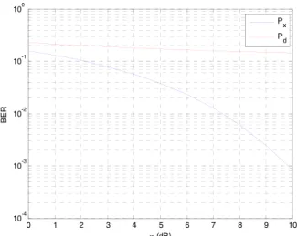
Fig. 2 shows the relationships between the bit error ratios and γ, and the other parameters are fixed as N = 1000, α = 0.1, λ = 0.1 and η = 10dB. Px decreases and
Pd increases with the increase in γ. Therefore, the BER
performances of the carrier symbol and watermark bit are competing. Consideringγ = σx/σu,Px decreases whenγ
increases, since the interferenceσuis small compared toσxin
this case. However, another interferenceσnremains constant
sinceη=σx/σnis fixed. Thus,Pxconverges to the constant
Qη/p1+λ2η2/N when γ tends to infinity, which can
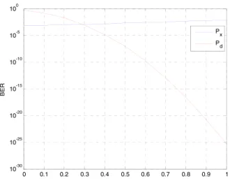
be obtained according to (16). Fig. 3 shows the relationships between the bit error ratios andη, and the other parameters are fixed asN =1000,α = 0.1,λ = 0.1 andγ = 10dB. Both Px andPd decrease with the increase in η, where η
is the traditional SNR. Therefore, the BER performances
FIGURE 2. Relationships between the bit error ratios andγ.
FIGURE 3. Relationships between the bit error ratios andη.
of the carrier symbol and watermark bit improve when the SNR increases. Fig. 4 shows the relationships between the bit error ratios andα, and the other parameters are fixed as N =1000,λ=0.1,γ =10dBandη=10dB. Considering α/γ 1,Px ≈ Q η/p 1+λ2η2/N. Therefore,P x has
smaller changes withαthanPd. Fig. 5 shows the relationships
between the bit error ratios andλ, and the other parameters are fixed asN =1000,α=0.1,γ =10dBandη=10dB. Consideringλ2η2/N 1,Pxalso has smaller changes with
λthanPd.
Figs. 2-5 show that the BER performance of the carrier symbol and the watermark bit depend on parametersN,α, andλ. Therefore, we can adjust the BER performance by changing the parameters.
Whenα=0 andλ=0, (16) becomes the BER formula
Pe=Q(η) (18)
which is only the BER expression for the binary digital mod-ulation signal without the watermark. Obviously,Px ≥ Pe,
i.e., the embedding of the watermark bit increases the BER of the original digital communication system. The watermark signal is a type of noise for the original carrier signal. Hence,
FIGURE 4. Relationships between the bit error ratios andα.
FIGURE 5. Relationships between the bit error ratios andλ.
the presence of the watermark bit interferes with the demod-ulation process of the original digital signal. This conclusion is also provided in the literature [3]. Therefore, we attempt to define the distortion according to the BER performance loss of the digital carrier.
IV. CHANNEL CAPACITY ANALYSIS
A. DISTORTION DEFINITION OF THE DIGITAL CARRIER
In the multimedia watermarking scheme, the watermark sig-nal energy is limited to ensure the imperceptibility of the watermark. Therefore, the distortion degree is commonly defined as E(D)=E[ks−xk]= α2+λ2σx2 Nσ2 u σ2 u (19)
in most available literature [19]. However, for digital commu-nication carrier, the distortion in (19) cannot directly reflect the performance loss of the original communication system. The demodulation BER of the carrier symbol should be intro-duced to the distortion definition, so we define the distortion for the digital carrier as
E(D)=lnPx Pe
(20)
wherePx and Pe are given by (16) and (18), respectively.
Because of the presence of the Q function, the expression of the distortion in (20) is notably complex.
To simplify the distortion constraint condition, we first simplify Px using Taylor expansion. In the embedding
scheme,αandλare the embedding parameters, which can be adjusted according to different application requirements, so we define
f (α, λ)=lnPx(α, λ) . (21)
Based on Taylor expansion theorem, Taylor expansion for the binary function is f(α0+h, λ0+k)≈f(α0, λ0)+ h ∂ ∂α+k ∂ ∂λ f(α0, λ0) +1 2 h ∂ ∂α +k ∂ ∂λ 2 f(α0, λ0). (22)
To expand f (α, λ) at point (0,0) using (22), the multiple derivatives off (α, λ)are calculated as
f (0,0)=lnQ(η) ∂f (0,0) ∂α = ∂f (0,0) ∂λ = ∂2f (0,0) ∂α∂λ =0 ∂2f (0,0) ∂α2 = η3e−η2/2 √ 2πQ(η) γ2 ∂2f (0,0) ∂λ2 = η3e−η2/2 √ 2πQ(η)N.
Therefore, we obtain the second-order Taylor expansion of f(α, λ)at point (0,0) as follows ˆ f(α, λ)=lnQ(η)+ η 3e−η2/2 2 √ 2πQ(η) 1 γ2α 2+ 1 Nλ 2 . (23) Substituting (23) into (21) yields
lnPˆ x(α, λ)=lnQ(η)+ η 3e−η2/2 2 √ 2πQ(η) 1 γ2α 2+ 1 Nλ 2 wherePˆ
x(α, λ) is the approximate expression ofPx(α, λ)
because fˆ(α, λ) is the approximate expression of f(α, λ). Then, the exponential operation is taken at both sides of the equation, and the approximate expression ofPxis
ˆ Px(α, λ)=exp η3e−η2/2 2 √ 2πQ(η) 1 γ2α 2+ 1 Nλ 2 ! Q(η). (24) Substituting (18) into (24) yields
ˆ Px Pe =exp η 3e−η2/2 2 √ 2πQ(η) 1 γ2α 2+ 1 Nλ 2 ! . Substituting the above expression into (20), we have
E(D)≈ η 3e−η2/2 2 √ 2πQ(η) 1 γ2α 2+ 1 Nλ 2 (25)
which is an approximation because Pˆ
x is the approximate
expression ofPx. According to the expression of E(D) in (25),
the distortion degree can be written as E(D)= η 3e−η2/2 2 √ 2πQ(η)l where l= 1 γ2α 2+ 1 Nλ 2 (26)
is a binary function ofαandλ, which can be modified in the watermarking algorithm. Therefore, parameterlis called the watermark index. The slope ofE(D) is η3e−η
2/2
2√2πQ(η), which only
depends onη. A largerηcorresponds to a larger slope, so the watermark indexlshould be sufficiently small to satisfy the distortion requirement.
With (26), we can further obtain α=γ
q
l−λ2/N. (27)
Eq. (27) is similar to the distortion constraint expression in [19] forl =1/γ2, but the distortion definitions of the two carriers are completely different. Substituting (27) into (17) yields the demodulation BER of the watermark bit as follows
Pd =Q s lN−λ2 (1−λ)2+1/η2 ! . (28)
B. WATERMARKING CHANNEL CAPACITY AND OPTIMAL PARAMETERS
From the watermarking transmission perspective, the decod-ing process of the watermark bit can be considered a part of the watermarking channel, so the watermarking communica-tion channel is equivalent to a discrete channel. According to the theory of discrete channel capacity [26], the generalized spread spectrum watermarking channel capacity in digital carrier is defined as
C=max
p(d)
H(d)−H d|d0 (29) whered is the transmitted symbol,d0is the received symbol, and H(d)= − n X i=1 p(di)log2p(di) H d|d0= − n X j=1 pdj0 n X i=1 pdi|dj0 log2pdi|dj0 p di|dj0 = p(di)p dj0|di n P i=1 p(di)p dj0|di .
For binary signals,d1 = 1 andd2 = −1, wherei = 1,2.
At the receiving end,d10 =1 andd20 = −1, wherei =1,2. In this case,H(d)−H d|d0is maximized whenp(d1)=
p(d2)=1/2, and the channel capacity C can be obtained.
In the generalized spread spectrum demodulation scheme, we have
p d10 =p d20= 1 2 p d20|d1 =p d10|d2=Pd
p d10|d1 =p d20|d2=1−Pd
wherePdis given by (28). Therefore, (29) becomes
Cd=1+Pdlog2Pd+(1−Pd)log2(1−Pd) . (30)
In practical applications,Pd <1/2 always holds, and we
have dCd dPd =log2 Pd 1−Pd <0.
Hence,Cdis a monotonous decreasing function ofPd, so
the channel capacityCd is maximum whenPdis minimum.
Therefore, the optimalλfor the maximalCdis obtained when
dPd/dλ=0; then
λ2−lN+1/η2+1λ+lN =0.
By solving the above equation, we obtain λopt= 1 2 lN+1/η2+1− q lN +1/η2+12 −4lN . (31) In [19], the distortion is defined asE[D] = E[ks−xk], which measures the waveform changes between the original signal and the marked signal. Then, the optimalλis calculated based on the distortion definition. In our paper, the original signal transmits the digital symbol, so the distortion is defined as E[D] = lnPx/Pe, which measures the BER changes
between the original signal and the marked signal. Based on this definition, we derive the optimalλ. Therefore, the two methods have different origins, and the conclusions are dif-ferent. Substituting (28) and (31) into (30) yields the final expression of the channel capacity.
Fig. 6 shows the relationship curves between the channel capacityCdandηwith differentλs, where the other
param-eters are fixed as N=100 and l=0.02. The simulation results verify that the maximal channel capacity is achieved withλopt
in (31). In the communication system, another key parameter is the SNR, which is
SNR=20log10σx
σn
=20log10η. (32)
Obviously, the upper bound of the channel capacity is Cd = 1, which can be achieved when the SNR tends to
infinity.
In practical application, we commonly expect that the BER performance will not significantly decrease after the water-mark is embedded; for example,Px/Pe = 2 is acceptable
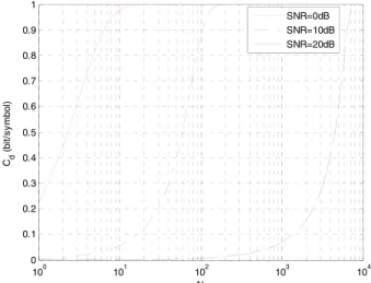
when E(D) = 0.6931. Keeping the distortion unchanged, the relationship curves between the channel capacity and the length of the spread spectrum sequence with different SNRs are shown in Fig. 7.
FIGURE 6. Relationships between the channel capacities andηwith differentλ.
FIGURE 7. Relationships between the channel capacity and the sequence length.
Obviously, the required length N for Cd = 1 increases
when the SNR increases because the watermark signal is more easily found when the SNR is larger. In this case, the watermark energy should be dispatched into more car-rier elements. Therefore, to achieve the maximal channel capacity, we must increase the length N of the spread spec-trum sequence when the SNR increases. The relationship in Fig. 6 can help us select the proper sequence length N for the fixed distortion E(D). As shown in Fig. 7, when SNR=0 dB,Cd tends to 1 when N>20. Therefore, we can
select N=20, which is the minimal sequence length for Cd =1. Similar, we can select N=200 for SNR=10 dB and
N=8000 for SNR=20 dB. The conclusions from Fig. 7 can help us select the proper sequence length in the system design.
V. CONCLUSION
In this paper, we investigate the generalized spread spec-trum watermarking scheme for binary digital signals. The distortion definition of the digital carrier is investigated by introducing the demodulation BER. Then, the capacity expression of the watermarking channel is re-investigated,
and the optimal parameter values for the maximal channel capacity are obtained. Finally, the relationship between the distortion and the watermarking channel capacity is inves-tigated to select the proper length of the spread spectrum sequence.
The spread spectrum watermark is a new technology to transmit the hidden information in the RF signal, so there are many new characters to be investigated. In the paper, we only establish the model of the spread spectrum watermark in the RF signals and discuss the channel capacity of the spread spectrum watermarking. In the future, we will investigate other watermark technologies in RF signals.
ACKNOWLEDGMENT
The authors would like to thank Prof. Chao Liu and Prof. Zhengyu Zhao for their support and valuable sugges-tions about the analysis of the channel capacity and BER. REFERENCES
[1] R. M. Gerdes, M. Mina, S. F. Russell, and T. E. Daniels, ‘‘Physical-layer identification of wired Ethernet devices,’’IEEE Trans. Inf. Forensics Security, vol. 7, no. 4, pp. 1339–1353, Aug. 2012.
[2] P. L. Yu, G. Verma, and B. M. Sadler, ‘‘Wireless physical layer authenti-cation via fingerprint embedding,’’IEEE Commun. Mag., vol. 53, no. 6, pp. 48–53, Jun. 2015.
[3] S. I. Park, J. Y. Lee, H. M. Kim, and W. Oh, ‘‘Transmitter identification signal analyzer for single frequency network,’’IEEE Trans. Broadcast., vol. 54, no. 3, pp. 383–393, Sep. 2008.
[4] J. Fang and M. Potkonjak, ‘‘Real-time watermarking techniques for sensor networks,’’ inProc. SPIE Security Watermarking Multimedia Contents V, vol. 5020, pp. 391–402, Jun. 2003.
[5] J. R. Smith, B. Jiang, R. Sumit, and P. Matthai, ‘‘ID modulation: Embed-ding sensor data in an RFID timeseries,’’ in Proc. Inf. Hiding, 2005, pp. 234–246.
[6] J. E. Kleider, S. Gifford, S. Chuprun, and B. Fette, ‘‘Radio frequency watermarking for OFDM wireless networks,’’ in Proc. IEEE ICASSP, May 2004, pp. 397–400.
[7] V. Kumar, J. M. Park, and K. Bian, ‘‘Blind transmitter authentication for spectrum security and enforcement,’’ inProc. ACM SIGSAC Conf. Comput. Commun. Secur. (CCS), 2014, pp. 787–798.
[8] V. Kumar, J. M. Park, T. C. Clancy, and K. Bian, ‘‘PHY-layer authentication by introducing controlled inter symbol interference,’’ inProc. IEEE Conf. Commun. Netw. Secur., Oct. 2013, pp. 27–35.
[9] X. Li, C. Yu, and M. Hizlan, W.-T. Kim, and S. Park, ‘‘Physical layer watermarking of direct sequence spread spectrum signals,’’ inProc. IEEE Military Commun. Conf. (MILCOM), Oct. 2013, pp. 476–481.
[10] X. Wu, Z. Yang, C. Ling, and X.-G. Xia, ‘‘Artificial-noise-aided physical layer phase challenge-response authentication for practical OFDM trans-mission,’’IEEE Trans. Wireless Commun., vol. 15, no. 10, pp. 6611–6625, Oct. 2016.
[11] V. Kumar, J. M. J. Park, and K. Bian, ‘‘PHY-layer authentication using duobinary signaling for spectrum enforcement,’’IEEE Trans. Inf. Forensics Security, vol. 11, no. 5, pp. 1027–1038, May 2016.
[12] ATSC Candidate Standard CS/110A: Synchronization Standard for Dis-tributed Transmission, ATSC, McLean, VA, USA, Mar. 2003
[13] J. G. Proakis,Digital Communication. New York, NY, USA: McGraw-Hill, 2001.
[14] I. J. Cox and M. L. Miller, ‘‘The first 50 years of electronic watermarking,’’ EURASIP J. Appl. Signal Process., vol. 1, pp. 126–132, Dec. 2002. [15] F. Hartung and M. Kutter, ‘‘Multimedia watermarking techniques,’’Proc.
IEEE, vol. 87, no. 7, pp. 1079–1107, Jul. 1999.
[16] A. Z. Tirkel, C. F. Osborne, and R. G. van Schyndel, ‘‘Image watermarking-a sprewatermarking-ad spectrum watermarking-applicwatermarking-ation,’’ inProc. IEEE 4th Int. Symp. Spread Spectr. Techn. Appl., Mainz, Germany, Sep. 1996, p. 785- 789.
[17] F. Hartung, J. K. Su, and B. Girod, ‘‘Spread spectrum watermarking: Malicious attacks and counterattacks,’’Proc. SPIE Security Watermarking Multimedia Contents, vol. 3657, pp. 147–158, Apr. 1999.
[18] D. Kirovski and H. Malvar, ‘‘Robust spread-spectrum audio watermark-ing,’’ inProc. Int. Conf. Acoust., Speech, Signal Process., vol. 3. May 2001, pp. 1345–1348.
[19] H. S. Malvar and D. A. F. Florêncio, ‘‘Improved spread spectrum: A new modulation technique for robust watermarking,’’IEEE Trans. Sig-nal Process., vol. 51, no. 4, pp. 898–905, Apr. 2003.
[20] X. Wang, Y. Wu, and B. Caron, ‘‘Transmitter identification using embed-ded pseudo random sequences,’’IEEE Trans. Broadcast., vol. 50, no. 3, pp. 244–252, Sep. 2004.
[21] I. J. Cox, M. L. Miller, and A. L. McKellips, ‘‘Watermarking as communi-cations with side information,’’Proc. IEEE, vol. 87, no. 7, pp. 1127–1141, Jul. 1999.
[22] M. Costa, ‘‘Writing on dirty paper,’’IEEE Trans. Inf. Theory, vol. 29, no. 3, pp. 439–441, May 1983.
[23] Y. Zhang, Z. Xu, and B. Huang, ‘‘Channel capacity analysis of the gen-eralized spread spectrum watermarking in audio signals,’’IEEE Signal Process. Lett., vol. 22, no. 5, pp. 519–523, May 2015.
[24] Z. Xu, C. Ao, and B. Huang, ‘‘Channel capacity analysis of the multiple orthogonal sequence spread spectrum watermarking in audio signals,’’ IEEE Signal Process. Lett., vol. 23, no. 1, pp. 20–24, Jan. 2016. [25] S. I. Park, J. Kim, D. Choi, H. M. Kim, and W. Oh, ‘‘RF watermark
backward compatibility tests for the ATSC terrestrial DTV receivers,’’ IEEE Trans. Broadcast., vol. 57, no. 2, pp. 246–252, Jun. 2011. [26] T. M. Cover and J. A. Thomas,Elements of Information Theory, 2nd ed.
Hoboken, NJ, USA: Wiley, 2006.
XU XIE (M’09) was born in Wuhan, China, in 1982. He received the M.S. and Ph.D. degrees in communication engineering from Huazhong University of Science and Technology, Wuhan, in 2010. He has taught graduate- and undergraduate-level courses on radio frequency signal processing and wireless communication theory. He is currently a Lecturer with the Depart-ment of Electronics and Engineering, Naval Uni-versity of Engineering, China. He has authored several IEEE journal papers in the area of radio frequency and com-munication systems. His research interests focus on the applications of communication signal processing and radio frequency circuit design.
ZHENGGUANG XUwas born in Wuhan, China, in 1981. He received the M.S. and Ph.D. degrees in communication engineering from Huazhong University of Science and Technology, Wuhan, China, in 2009. He is currently a Lecturer with the College of Electronics and Communications, Huazhong University of Science and Technology. His research interests include signal processing and information hiding.
HUI XIEwas born in Huangshi, China, in 1977. He received the M.S. and Ph.D. degrees in commu-nication engineering from the College of Electron-ics Engineering, Naval University of Engineering, China, in 2008. He is currently an Associate Pro-fessor with the Naval University of Engineering. His research interests include wireless communi-cation, electromagnetic wave propagation, antenna design, and radio frequency communication.