TECHNICALUNIVERSITY OF CLUJ-NAPOCA
ACTA TECHNICA NAPOCENSIS
Series: Applied Mathematics, Mechanics, and Engineering Vol. 62, Issue IV, November, 2019
RESEARCH OF FUEL INJECTION DUTY ON A SPARK IGNITED ENGINE
Doru-Laurean BĂLDEAN
Abstract: Using a spark ignited Mitsubishi engine, with a volumetric capacity of 1997 cm3, this study presents the testing results of fuel injection duty and ignition advance in relation to the manifold pressure and throttle position. The later parameters are controlled by the driver’s applied force upon the accelerator pedal. Displacement of the last one is digitally translated or encoded as engine’s load. Peak value of the crank-shaft speed in this case study is close to 3000 rpm.
Key words: control, engine, fuel, injection, spark ignition
1. INTRODUCTION
The last fifty years or so have been very significant in terms of fuel injection control and optimization both for spark ignition and other thermal engines. Fuel injection is one of the most important and influencing factors in engine’s operation due to its mark upon performance and pollution. In the present scientific work is outlined a short overview on the testing protocol and experimental result from a rally spark ignited engine. Mitsubishi developed some of the most competitive power-trains for series models as well as motor-sport engines. In the present paper is studied the spark ignited engine in regard with fuel injection duty. Following trend-lines of fuel injection duty and other important parameters such as ignition advance, manifold pressure, crank-shaft speed, in specific regimes gives us the possibility to obtain a valuable insight on the relation between driver’s request and throttle position, on one hand, respectively engine’s operating regime and its
performance on the other hand. The
experimental research of actual values and their trends, beside the adjustment of the spark ignited engine, were made due to the necessity for a better understanding of mechanical effects given by extreme stresses in operation. Using digital
pressure, which in turn dictate the engine speed and torque [4, 5].
Important advanced and applied methods for researching the engine’s parameters and components were designed and used [6, 7, 8].
Highly digital and smart features are giving their support and assistance in managing both the production and later control in optimal operation as well as in servicing or technical investigations.
The main purpose of the paper is to present the fuel injection duty as a function of throttle position, engine speed and manifold pressure as well as to comment on trend-lines. Specific objectives are to relate the fuel injection duty with all the available parameters of the engine and to highlight the practical opportunities.
2. MATERIALS AND METHOD
The present research is an experimental approach, using a specific power-train on the basis of predesigned methodology. Figure 1 shows the architecture of the spark ignited engine studied with the volumetric capacity of 1997 cm3.
Fig. 1.Simple schematic of spark ignited engine
According to Figure 2 methodology of the study is pointing out the parameters which are
considered in spark ignited engine control
procedure that makes it easy to understand the
importance of mechanical values and
mathematical modelling.
Fig. 2. Methodology of the fuel injection duty control
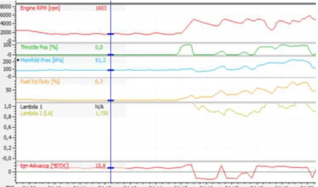
Figure 3 presents the evolution of first set of recorded parameters, such as engine speed and temperature.
Fig. 3. Engine parameters screen shot from Motec
In Figure 4 real values are considered individually alongside the recording timeline.
Fig. 4. Fuel injection duty variation besides other actual values in the recorded time frame
3. MATHEMATICAL MODELS
Fuel injection duty in relation with throttle position is given by polynomial equation (1):
21 . 7 T 0983 . 0 T 10
1
Finj.duty =− 4⋅ p2+ ⋅ p+ , [%]. (1) where: Finj.duty is fuel injection duty in %; Tp – throttle position, expressed in %.
The excess air available is correlated with fuel injection being expressed by equation (2):
4 . 747 7
, 984 16.1
3
-F 2
duty .
inj = ⋅λ + ⋅λ− , [%]. (2)
4. RESULTS AND OBSERVATIONS
Applied results are mainly concentrated toward the fuel injection duty representation versus throttle position, engine speed and other important parameters, according to figures 5-9.
Fig. 5. Fuel injection duty versus throttle position
Fig. 6. Fuel injection duty versus manifold pressure
Fig. 7. Fuel injection duty versus lambda
Fig. 8. Fuel injection duty versus ignition advance
Fig. 9. Fuel injection duty versus engine speed
Figures 10-14 show the values vs. speed.
Engine speed is beside the throttle position one of the most important operational parameters which dictates the performance of the power-train, especially power output. Thus it is a good opportunity to study its effect upon other secondary actual values during operation.
Fig. 10. Manifold pressure versus engine speed
Fig. 11. Aux duty ECU versus engine speed
Fig. 12. Ignition advance versus engine speed
Fig. 13. Lambda coefficient versus engine speed
Fig. 14. Cam (shaft) aim in relation to engine speed
Cross-values are recorded in Figures 15-28.
y = -1E-04x2+ 0,0983x + 7,2101
R² = 0,9721
0 5 10 15 20
0 20 40 60 80 100
F ue l I nj . D ut y, [ % ]
Throttle Pos, [%]
y = 0,0211x2- 3,4208x + 144,6
R² = 0,9171 0
5 10 15 20
85 90 95 100 105
F ue l I nj . D ut y, [ % ]
Manifold Pressure, [kPa]
y = -316,09x2+ 984,74x - 747,42
R² = 0,8182 0 5 10 15 20 25
1,4 1,5 1,6 1,7 1,8
F ue l I nj . D ut y, [ % ] Lambda, [-]
y = -0,0583x2+ 3,4283x - 33,225
R² = 0,8587
0 5 10 15 20
14 16 18 20
F ue l I nj . D ut y, [ % ]
Ignition advance, [°BTDC]
y = -5E-06x2+ 0,0322x - 30,759
R² = 0,8245 0
5 10 15 20
1000 1500 2000 2500 3000
F ue l I nj . D ut y, [ % ]
Engine speed, [rpm]
y = -7E-06x2+ 0,0402x + 42,748
R² = 0,6416 0 20 40 60 80 100 120
1000 1500 2000 2500 3000
M an if ol d P re ss ur e, [k P a]
Engine speed, [rpm]
y = 2E-06x2+ 0,0182x + 5,8375
R² = 0,8583 0 20 40 60 80 100
1000 1500 2000 2500 3000
A ux 3 D ut y E C U , [ % ]
Engine speed, [rpm]
y = 0,0093x + 1,3503 R² = 0,9881
0 10 20 30 40
1000 1500 2000 2500 3000
Ig ni ti on a d va nc e, [° B T D C ]
Engine speed, [rpm]
y = -2E-07x2+ 0,0006x + 1,2765
R² = 0,9511
0 0,5 1 1,5 2
1000 1500 2000 2500 3000
L am bd a, [ -]
Engine speed, [rpm]
y = 0,0104x - 19,186 R² = 0,9817
-5 0 5 10 15
1000 1500 2000 2500 3000
C am A im E rr or I nl et , [° ]
Fig. 15. Intake manifold pressure versus ignition angle
Fig. 16. Lambda coefficient related to the ignition angle
Fig. 17. Camshaft aim inlet versus ignition advance
Fig. 18. Combustion initiation vs. fuel injection duty
Fig. 19. ECU auxiliary duty versus fuel injection duty
Fig. 20. Crank-shaft speed correlated to throttle position
Fig. 21. ECU auxiliary duty vs. throttle position
Fig. 22. Injection advance versus to throttle position
Fig. 23. Excess air coefficient related to throttle position
Fig. 24. Intake manifold pressure versus throttle position
Fig. 25. Ignition advance in relation with intake pressure
Fig. 26. Lambda coefficient versus manifold pressure
Fig. 27. Accelerator versus manifold pressure
Fig. 28. Ignition advance correlated to lambda coefficient
y = -0,069x2+ 4,2075x + 40,234
R² = 0,6887 50
70 90 110
14 16 18 20
M an if ol d P re ss ur e, [ kP a]
Ignition advance, [°BTDC]
y = -0,0021x2+ 0,0738x + 1,101
R² = 0,931 1,5
1,6 1,7 1,8
14 16 18 20
L am bd a, [ -]
Ignition advance, [°BTDC]
y = -0,0097x2+ 1,6177x - 26,83
R² = 0,9992
-10 -5 0 5 10 15
0 5 10 15 20 25 30 35
C am A im E rr or In le t, [ °]
Ignition advance, [°BTDC]
y = 0,1333x2- 2,124x + 25,118
R² = 0,9216
0 10 20 30 40
0 2 4 6 8 10 12 14 16 18 20
C om b us ti on st ar t, [ °B T D C ]
Fuel Inj. Duty, [%]
y = 0,5678x2- 10,032x + 85,097
R² = 0,9325
0 50 100
0 2 4 6 8 10 12 14 16 18 20
A ux 3 D ut y E C U , [% ]
Fuel Inj. Duty, [%]
y = 0,1771x2- 8,4908x + 1713,9
R² = 0,7943 0
1000 2000 3000 4000
0 20 40 60 80 100
C ra nk s pe ed , [r ot /m in ]
Throttle Pos, [%]
y = 0,0067x2- 0,3644x + 43,311
R² = 0,9112 0
20 40 60 80
0 20 40 60 80 100
A ux 3 D ut y E C U , [% ]
Throttle Pos, [%]
y = 0,0016x2- 0,0697x + 17,099
R² = 0,8435 0
10 20 30 40
0 20 40 60 80 100
Ig ni ti on a dv an ce , [° B T D C ]
Throttle Pos, [%]
y = -3E-05x2+ 0,0017x + 1,7444
R² = 0,6068 1,5
1,6 1,7 1,8
0 20 40 60 80 100
L am bd a, [ -]
Throttle Pos, [%]
y = 0,0003x2+ 0,109x + 90,12
R² = 0,9752 50
70 90 110
0 20 40 60 80 100
M an if ol d P re ss ur e, [ kP a]
Throttle Pos, [%]
y = 0,1012x2- 18,926x + 901,21
R² = 0,8096 0
10 20 30 40
85 90 95 100 105
Ig ni ti on a dv an ce , [° B T D C ]
Manifold Pressure, [kPa]
y = -0,0014x2+ 0,262x - 10,426
R² = 0,5381 1,4
1,5 1,6 1,7 1,8
85 90 95 100 105
L am bd a, [ -]
Manifold Pressure, [kPa]
y = 0,1804x2- 27,437x + 1010,1
R² = 0,9777
-50 0 50 100 150
85 90 95 100 105
A cc el er at or , [ % ]
Manifold Pressure, [kPa]
y = -176,87x2+ 527,82x - 365,07
R² = 0,859 0
10 20 30 40
1,4 1,5 1,6 1,7 1,8
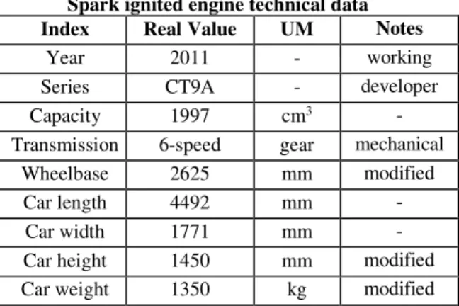
The practical measurements were taken on a Mitsubishi Lancer Evo9 with technical data presented in Table 1.
Table 1
Spark ignited engine technical data
Index Real Value UM Notes
Year 2011 - working
Series CT9A - developer
Capacity 1997 cm3 -
Transmission 6-speed gear mechanical Wheelbase 2625 mm modified
Car length 4492 mm -
Car width 1771 mm -
Car height 1450 mm modified Car weight 1350 kg modified
Observing the practical measurements and their trend-lines on each graph is possible to issue few conclusions on the specific matter.
5. CONCLUSION
Fuel injection duty being the hydrocarbon loading presented as a percent from maximum amount of liquid fuel introduced in a cylinder during a stroke, gives an expression of stress and fluid dynamics at a specific time.
The pick fuel injection duty (at 100% throttle position) was determined at 3062 rpm. At this moment of the operating regime the lambda value was 1.435, meaning that the excess air made a quite lean combustion. Practical recording shows at the same instance that manifold pressure was exactly 103.2 kPa leading us to assume the turbo charger boosted already. A minimum of 6.6 % fuel injection duty was measured zero accelerator position and with the lowest combustion starting angle recorded at 15.3 °BTDC.
The peak manifold pressure (at 103.2 kPa) was recorded for the 100% accelerator position and 29 °BTDC combustion start angle, respectively the lowest value of air intake pressure has been 87.9 kPa at 18 °BTDC spark advance.
Lowest fuel injection duty recorded at the 82.8°C engine temperature and 1.75 lambda coefficient, respectively the highest fuel
injection duty has been correlated with a small increase (of 0.5 %) in engine temperature.
Mapping the fuel injection duty in relation with other operating parameters gives the opportunity of better understanding the engine’s calibration and adjusting procedures. Injection process is quite significant and gives effects on consumption, fuel efficiency, pollution and carbon footprint. Fuel injection duty also dictates the qualitative level of air-fuel composition and thus influences the combustion phase of the engine’s cycle.
Testing the car in real environment allowed the possibility to validate the assumption of interdependence between fuel injection duty and turbo charger operation as well as the mapping of the optimal operation pole. Most appreciated output performance at the testing moment was at 23.4 °BTDC ignition angle and 2319 rpm due to momentary optimal values stored with a 15.1 % fuel injection duty, respectively 83 °C engine temperature.
The air intake temperature was 42 °C and barometric pressure was 97.8 kPa. Throttle position for this step was 94 %. Due to the fact that the spark ignited engine is installed on a competition vehicle involved in motor-sport races the usual operating regime is above 80 % throttle position. Even in this case it is well seen to consider the fuel efficiency and even environmental impact.
Developing a well balanced operational map with the most refined efficiency means to have better digital control. Further measurements will be made as on board recording is available and easy to use in other investigations.
6. REFERENCES
[1] Andrei, L., et al, Applied Measurements and Instrumentation for Improving Diagnostic Devices and Systems in Metropolitan Polluted Environments with Nitric and
Carbon Oxides, IFMBE Proceedings book
series (IFMBE, volume 71), MEDITECH 2018, ClujNapoca, 2018.
[3] Borza, E.V., et al, Research Concerning Fuel Economy Coefficient and Carbon Foot Print in Various Conditions for a City Compact Size Vehicle with Digital Control for a Green Solution and Method at Technical University
from Cluj-Napoca, Proceedings of the
International Congress of Automotive and Transport Engineering, In: Burnete N., Varga B. (eds) Proceedings of the 4th International Congress of Automotive and Transport Engineering (AMMA 2018). Proceedings in Automotive Engineering. Springer, Cham, pp. 181-189, ISBN978-3-319-94408-1. [4] Botean, A.I., Influence of working fluid
pressure on the power of a Stirling gamma
engine, Acta Technica Napocensis-Series:
Applied Mathematics, Mechanics, and Engineering, 61 (2), 2018. Accessed July 3, 2019.
[5] Botean, A.I., Optimization of a Γ-Type Stirling engine performance based on an
experimental approach, Acta Technica
Napocensis-Series: Applied Mathematics, Mechanics, and Engineering, 62 (2), 2019. Accessed Sept. 3, 2019.
[6] Cherecheș, I.A., et al, Contribution of developing advanced engineering methods in interdisciplinary studying the piston rings from 1.6 spark ignited Ford engine at Technical University of Cluj-Napoca, IOP Conf. Ser.: Mater. Sci. Eng. 252 012072, doi.org/10.1088/1757-899X/252/1/012072, 2017.
[7] Crișan-Lupa, L.V., et al, Research applied to exhaust gas after-treatment systems in 1.6 L Zsg 416 Ford engine, In: Andreescu C., Clenci A. (eds) Proceedings of the European Automotive Congress EAEC-ESFA 2015.
Springer, Cham, Online ISBN 978-3-319-27276-4, 2015.
[8] Cordoş, N., et al., Automobiles.
Construction. Wear. Evaluation /
Automobile. Construcţie. Uzare. Evaluare, Ed. Todesco, ISBN 973-99779-7-9, Cluj-Napoca, 2000.
[9] Ferenți, I., et al., Artificial intelligence implemented in rally vehicles for increasing energetic efficiency in competitions / Inteligența artificială implementată în autovehicule de raliuri pentru creșterea eficienței energetice în competiții,Science and engineering/Știință și inginerie, 34 (18), Mai 29, 2018. Accessed June 3, 2019. [10] Ferenți, I., et al., The analize of specific
parameters for spark ignited engine
operational cycle depending on
altitude/Analizamărimilorspecificecicluluifu
ncțional al unui motor cu
aprindereprinscânteieînraport cu
altitudinea,Science and engineering/Științăși inginerie, 26 (46), January 31, 2015. Accessed June 3, 2019.
[11] Hodor, A., et al., Some considerations about 3D replication of complex surfaces,
Acta Technica Napocensis-Series: Applied Mathematics, Mechanics, and Engineering, 56 (1), 2013. Accessed July 3, 2019.
[12] Marincaș, C., et al., Contributions to the experimental research of Electronic Diesel Control (EDC) module operation in relation with supply of the N47 engine from BMW
320d (E90) automobile, Science and
engineering/Științășiinginerie, 31 (82), May 3, 2017. Accessed July 3, 2019.
CERCETAREA SARCINII INJECŢIEI DE COMBUSTIBIL PE UN MOTOR CU APRINDERE PRIN
SCÂNTEIE
Rezumat: Utilizând un motor Mitsubishi cu aprindere prin scânteie, cu o capacitate volumetrică de 1997 cm3, acest studiu
prezintă rezultatele testării sarcinii injecţiei de combustibil şi a avansului la aprindere în raport cu presiunea din galeria de admisie şi poziţia clapetei. Aceşti din urmă parametri sunt controlaţi prin forţa aplicată de către şofer asupra pedalei de acceleraţie. Deplasarea acesteia din urmă este codificată sau tradusă digital ca sarcină a motorului. Valoarea de vârf a turaţiei în acest studiu de caz este apropiată de 3000 rpm.
Cuvinte cheie: control, motor, combustibil, injecție, aprindere prin scânteie