Interference Effects
with
Surface Plasmons
Interference Effects
with
Surface Plasmons
Proefschrift
ter verkrijging van
de graad van Doctor aan de Universiteit Leiden,
op gezag van Rector Magnificus prof.mr. P.F. van der Heijden, volgens besluit van het College voor Promoties
te verdedigen op donderdag 10 januari 2008 klokke 15:00 uur
door
Nikolay Victorovich Kuzmin
Promotor: Prof. Dr. G.W. ’t Hooft (Philips Research / Universiteit Leiden) Copromotor: Dr. E.R. Eliel (Universiteit Leiden)
Referent: Dr. J. G´omez Rivas (AMOLF / Philips Research)
Leden: Prof. Dr. L. Kuipers (AMOLF /
Universiteit Twente)
Prof. Dr. H.P. Urbach (Technische Universiteit Delft) Prof. Dr. M.W. Beijersbergen (Cosine / Universiteit Leiden) Dr. M.P. van Exter (Universiteit Leiden)
Prof. Dr. J.P. Woerdman (Universiteit Leiden) Prof. Dr. J.M. van Ruitenbeek (Universiteit Leiden)
The work presented in this thesis is part of the scientific program of the “Stich-ting voor Fundamenteel Onderzoek der Materie (FOM)” and has been made possible by financial support from the “Nederlandse Organisatie voor Weten-schappelijk Onderzoek (NWO)”.
Contents
1 Introduction 1
1.1 Basic properties of metals . . . 1
1.2 Surface plasmons . . . 2
1.2.1 What is a surface plasmon? . . . 2
1.2.2 Surface plasmon dispersion and attenuation . . . 5
1.2.3 Surface-plasmon excitation . . . 6
1.3 Outline of thesis . . . 9
2 Plasmon-assisted two-slit transmission: Young’s experiment revisited 13 2.1 Introduction . . . 14
2.2 Idea . . . 14
2.3 Experiment . . . 14
2.4 Results . . . 15
2.5 Theoretical calculation . . . 19
2.6 Conclusions . . . 21
2.7 Appendix: Erasing the interference . . . 22
3 Enhanced spatial coherence by surface plasmons 27 3.1 Introduction . . . 28
3.2 Experiment . . . 29
3.3 Results . . . 29
4 Bouncing surface plasmons 35
4.1 Introduction . . . 36
4.2 Experiment . . . 37
4.3 Results . . . 39
4.4 Discussion . . . 41
4.5 Conclusions . . . 47
4.6 Appendix: Slowed-down surface plasmons . . . 48
5 Phase factors in light-plasmon scattering 51 5.1 Introduction . . . 52
5.2 Heuristic models . . . 54
5.2.1 Two-slit system . . . 55
5.2.2 Three-slit system . . . 55
5.3 Experimental setup . . . 58
5.4 Results and Discussion . . . 59
5.4.1 Signal modulation along the slanted slit . . . 60
5.4.2 Coupling phase slip . . . 62
5.4.3 Plasmon tunneling . . . 64
5.4.4 Slanted slit as a source of surface plasmons . . . 65
5.5 Conclusions . . . 67
5.6 Appendix: Towards a complete picture of surface-plasmon scat-tering . . . 68
6 Retardation effects in sub-wavelength slits in thin metal films near cut-off 73 6.1 Introduction . . . 74
6.2 Experiment . . . 77
6.3 Experimental results . . . 78
6.3.1 Transmission of purely TE/TM polarized incident light. 79 6.3.2 Polarization analysis of transmitted light . . . 80
6.4 Discussion . . . 83
6.5 Conclusions . . . 87
7 Short-wavelength surface plasmons 89 7.1 Introduction . . . 90
7.2 Dispersion and Damping . . . 90
7.3 Experiment . . . 91
7.4 Results and Discussion . . . 93
Contents
Bibliography 99
Samenvatting 109
Интерференционные эффекты с поверхностными плазмонами
(in Russian) 117
Волны в природе . . . 117 Поверхностные плазмоны . . . 118 Тема и содержание диссертации . . . 122
Curriculum Vitae 135
Acknowledgements 137
Chapter 1
Introduction
1.1
Basic properties of metals
Since ancient times people have been intrigued by the sparkling properties of crystals and the shimmering of shiny metals like gold and silver. These pre-cious metals were valued by many cultures and used as coinage, for ornaments and jewelry.
Polished silver surfaces were also used as mirrors and legend has it that, during the second Punic war, Archimedes used a large number of mirrors to set afire a hostile Roman fleet anchored off the bay of Syracuse, by focusing the light of the sun on the ships [1, 2]. Gold was also used to make stained glass, well known from the windows of many cathedrals around Europe and, much earlier, to make the base glass of the well-known Lycurgus cup [3]. An understanding of the physics of these phenomena came much later, in the 19th and 20th centuries, when scientists came up with a theoretical description of the optics of metals.
In one of these models, the so-called free-electron model, a metal is de-scribed as a collection of ions, that are fixed in space, and a gas of free con-duction electrons that interact with themselves and with the ions through the Coulomb force [4, 5]. The interacting system of ions and electrons is basically a plasma where the ions have much larger inertia than the electrons. When this plasma interacts with an electromagnetic field, the electrons will execute a forced oscillation relative to the ions. The amplitude and phase of this os-cillation relative to that of the driving electromagnetic field depends on the frequency of the latter relative to the eigen oscillation frequency of the plasma, the so-called plasma frequency ωp:
ωp2=
ne2
0m∗,
which follows directly from a simple harmonic oscillator description of the response of the electrons [4]. Heren is the electron density,eand m∗ are the charge and effective mass of the electron. The quantum of this oscillation is called a plasmon, or, since the electrons are oscillating in the metal volume, a
bulk plasmon. For gold and silverωp∼1016 rad/s.
The plasma oscillation is damped, for instance, due to the scattering of the electrons off impurities, lattice defects, etc. Phenomenologically, this is taken into account by introducing a damping constantγ, and in the Drude model [4] the relative dielectric function is expressed as:
˜
(ω) = 1− ω
2 p
ω(ω+iγ). (1.2)
Hereγ represents the collision rate of the electrons and determines the damp-ing of the plasma oscillation. The Drude model is a simple and convenient model that explains, for instance, the high reflectivity of metals in the vis-ible and infrared, i.e. below the plasma frequency. In that spectral regime the real part of the dielectric function is negative (ω) ≡Re(˜) <0 and the incident electromagnetic radiation is back reflected by the plasma, penetrat-ing into the metal only over a distance of the order of λ/2π|m|, which is
25 nm for case of gold at λ = 0.8 µm. In the UV range, i.e., above the plasma frequency, (ω) is positive and the metal is transparent for incident electromagnetic radiation.
1.2
Surface plasmons
In 1957 Ritchie theoretically showed [6] that, when a metal is in the form of a thin foil, a second type of plasma resonance can occur atω=ωp/
√
2. Here the charge oscillations take place at the top and bottom interfaces of the metal film. This prediction was confirmed in an experiment by Powell and Swan [7].
1.2.1 What is a surface plasmon?
1.2 Surface plasmons
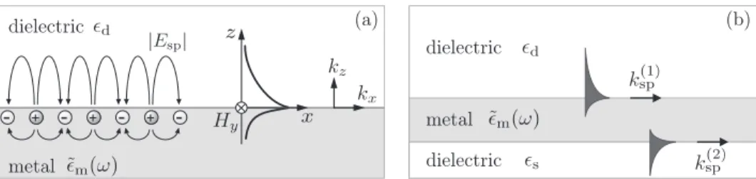
Figure 1.1. (a) Schematic picture of the charge distribution of a sur-face plasmon and the associated electromagnetic wave. (b) Metal film, sandwiched between two dielectrics, carrying surface plasmons at each interface. When the metal film is thin (50 nm) the plasmons of both interfaces can couple via their evanescent fields.
In the recent literature [9] a distinction is made between surface plasmons, that propagate on essentially extended interfaces (length scale much larger than the optical wavelength), called surface-plasmon polaritons, andlocalized
surface plasmons which are associated with metal objects or protrusions that are much smaller than the wavelength [10, 11]. The latter are referred to as “particle plasmons” and are responsible, e.g., for the optical properties of the Lycurgus cup mentioned earlier.
The boundary conditions for the electromagnetic field require that the magnetic field of a surface plasmon, propagating along a smooth and flat interface, is parallel to the metal surface. With the SP, propagating in the x-direction as a transverse magnetic wave, we have Hx = Hz = 0. The propagation constant of the SP is complex:
˜
kx ≡ksp+ikx= ω
c
˜ md
˜
m+d,
(1.3)
with ˜m and d the dielectric functions of the metal and of the dielectric,
respectively. Note that ˜m is complex: ˜m=m+imwith m<0.
The magnetic component of the surface-plasmon field can be written as
Hsp= ˆy Hyf(z) exp[i(˜kxx−ωt)], (1.4)
with
f(z) =
exp(−qdz) for z >0,
exp(+qmz) for z <0,
where ˜k2
x−qi2=i(ω/c)2,i= m,d. In the limit that|m| d one has
qd ω
c d
|m|, qm ω
c
|m|,
(1.6)
showing that the surface plasmon field decays in thez-direction over a length roughly equal to λ|m|/2πd in the dielectric and λ/2π
|m|in the metal. For large values of|m|the field extends well into the dielectric (microns) and only marginally into the metal (nanometers). The fact that the electromag-netic field of a surface plasmon is confined to the metallo-dielectric interface makes SP into a highly sensitive probe of such interfaces [12, 13].
The electric field of the surface plasmon has both a longitudinal (x) and transverse (z) components with ratio
Ex
Ez =−i
qd
ksp
for z >0,
Ex
Ez = +i
qm
ksp
for z <0,
(1.7)
so that fields in both media are “elliptically” polarized.
An important property of the surface plasmon is that it is attenuated during propagation, basically due to dissipation in the metal — the electrons are inelastically scattered. The field attenuation length, i.e. the length over which the SP field amplitude decays by factor e in the x direction, is given by Lsp = 1/kx. For gold and silver Lsp spans from millimeters in the
mid-infrared range to less than a micron in the blue part of the visible spectrum (see Fig. 1.3b). A second cause of surface plasmon damping is surface roughness [8, 14].
1.2 Surface plasmons
(a) (b)
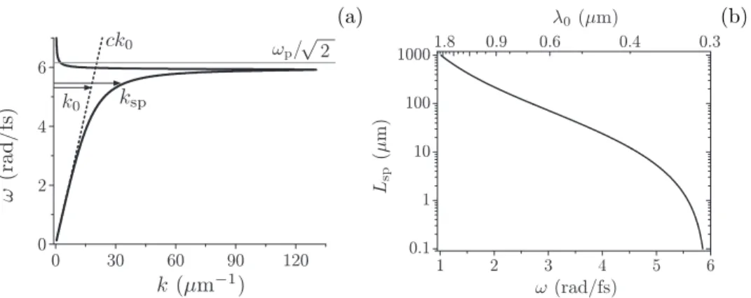
Figure 1.2. (a) Dispersion of the surface plasmon on the sodium-vacuum interface (solid black line). The dashed line shows the light line (ω =ck0). Arrows show that the SP wavenumber ksp exceeds the free radiation wavenumberk0. (b) Surface plasmon propagation length Lsp on the sodium-air interface.
1.2.2 Surface plasmon dispersion and attenuation
The dispersion of the surface plasmon, i.e., the dependence of the SP fre-quency ω on its wave number ksp shows how the properties of the surface
plasmon change in various frequency ranges, and determines the value of both the phase and group velocities. To gain a conceptional understanding of the dispersive properties of a surface plasmon we return to the Drude model (see Eq.(1.2)) for the dielectric function of the metal, and assume the dielectric to be dispersionless. Metallic sodium behaves very much like a Drude metal, i.e., the dispersion of its dielectric function can accurately be fitted with the Drude model yielding ωp = 8.7 rad/fs and γ = 0.042 fs−1 [18]. The results for the
SP dispersion and the damping on the sodium-vacuum interface are shown in Fig. 1.2.
At low frequencies (near IR and IR, ω < 2 rad/fs) the SP on the Na-vacuum interface has a photon-like nature, i.e., its phase velocity is very close to the speed of light: it extends mainly in the vacuum rather than in the metal. At optical frequencies the dispersion curveω(ksp) starts to bend over,
which results in a decrease of the SP group velocityvgr=∂ω/∂ksp and higher
damping due to deeper penetration of the SP into the metal. In the limit that ω → ωp/
√
2 the SP becomes a localized excitation, since vgr → 0. At the
largest value ofksp (ksp ∼130µm−1) the dispersion curve is seen to fold back.
(a) (b)
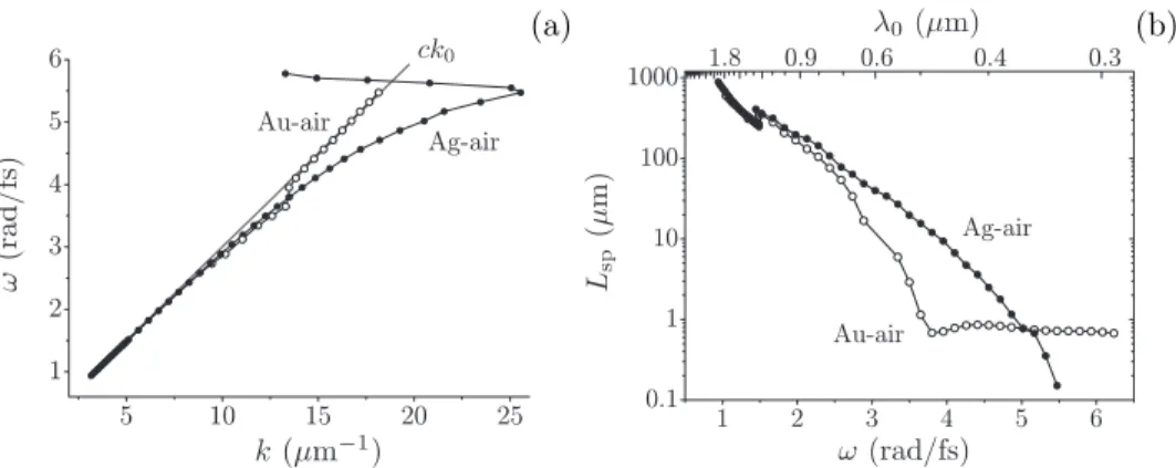
Figure 1.3. The dispersion (a) and damping (b) of a surface plasmon on gold-air (◦) and silver-air (•) interfaces. Data are based on tabulated values for the dielectric functions of metals [22].
strongly damped that the concept of a propagating wave loses its meaning. Figure 1.2b shows how the attenuation length Lsp varies as a function of
the frequency of the surface plasmon. While for frequenciesω <4.7 rad/fs the relationship between Lsp and ω is almost exponential, for higher frequencies
Lsp drops even much more rapidly.
In most practical cases it is convenient to use metals that are less reactive than sodium, e.g. gold or silver. The dispersion and damping of a surface plasmon on a gold-air or silver-air interfaces are shown in Fig. 1.3. Clearly, silver behaves much better than gold insofar that the wavenumber of the sur-face plasmon on the silver-air intersur-face deviates much more from the light line than on the gold-air interface. Additionally silver shows a lower SP attenua-tion compared to gold. However, gold doesn’t oxidize in air, which makes it easy to study surface plasmons on the gold-air interface while thin silver layers are prone to chemical attack in air [23]. Note that it is still possible to study SPs on the silver-dielectric interface when the silver layer is buried or freshly applied.
1.2.3 Surface-plasmon excitation
The value of the SP wave numberksp is larger than that of light in free space
k0(see Fig. 1.2a). Consequently, there is a wave-vector mismatch between the
pro-1.2 Surface plasmons
Figure 1.4. Surface-plasmon excitation schemes: a) Kretschmann con-figuration; b) double-layer Kretschmann concon-figuration; c) Otto configu-ration; d) excitation with a SNOM probe; e) light diffraction on a single surface feature; f) excitation by means of a diffraction grating.
posed by Kretschmann and Otto [25, 26], are still widely used, especially in surface-plasmon spectroscopy [27, 28]. These schemes require careful angular tuning of the setup to couple to the surface plasmons. A scanning near-field optical microscope (SNOM) tip (Fig. 1.4d) is also a widely used powerful tool for both local excitation and probing of the surface plasmons [29–33]. Finally, a surface feature like a protrusion, grating, or surface roughness can be em-ployed to excite and de-excite SPs (Fig. 1.4e–f). In all cases the polarization of the incident radiation has to be chosen so as to optimally couple with a surface plasmon. In the present thesis, where we use one, two or three slits to launch and detect surface plasmons, the incident light has to be polarized perpendicular to the slit axis.
Obviously, the detailed shape of the surface feature has a major impact on the excitation probability of a surface plasmon. Naively, one can say that for normally incident light the excitation probability is determined by the square of the Fourier transform of the surface feature at the wave vector of the surface plasmon. For a rectangular bump of width a the Fourier spectrum is shown in Fig. 1.5. It is seen to rapidly drop off and to become zero whenk= 2π/a. This suggests that, in order to efficiently excite surface plasmons one should have ksp 2π/a, i.e. a λ. In that case the SP excitation probability only
weakly depends onλ.
Figure 1.5. Fourier spectrum of a step function.
one of the studied structures is shown in Fig. 1.6 together with the light pattern behind it, observed under two illumination conditions. The sample is a 200 nm thick gold film, deposited on top of 0.5 mm thick glass plate with a 10 nm Ti adhesion layer between the gold and the glass. The gold film is perforated by two parallel, 0.2 µm wide and 50 µm long slits, that are 25 µm apart. One of the two slits is illuminated by a tightly focused laser beam with a spot size of order 5µm, much smaller than the slit separation. The laser is tuned to a wavelength of 800 nm where the SP on the Au-air interface is weakly damped (Lsp 90 µm). The polarization of light can be chosen to be either TE or
TM, i.e. parallel or perpendicular to the length of the slits. The dark side of the sample is imaged on a CCD camera by means of a microscope objective (40/0.65). Figures 1.6b and c show the case for TE and TM illumination, respectively. Under TM illumination the non-illuminated slit is bright being “fed” by the SP launched by the illuminated slit at left.
1.3 Outline of thesis
1.3
Outline of thesis
The work in this thesis describes a series of interlinked experiments on surface plasmons propagating along a metallo-dielectric interface. The metal is either gold or silver applied as a thin (≈200 nm thick) film on top of a transparent substrate with a binding layer in between. That film is perforated by a num-ber of long, sub-wavelength slits, separated by many optical wavelengths (see Fig. 1.6). The common idea behind all the experiments is that each of the slits has a number of functions:
1. It transmits part of the incident light.
2. It scatters part of the incident light into a surface plasmon that propa-gates along the interface.
3. It scatters part of an incident surface plasmon into light, being visible at both the front and rear sides of the sample.
This list is not complete; however, it enumerates the effects that dominate the experimental results described in this thesis.
In the second Chapter we study a sample consisting of a 200 nm thick gold film on top of a glass substrate with a titanium adhesion layer between the gold and the glass. The metal film is perforated by a series of double slits, each of the slits being≈50µm long and 200 nm wide. There are five sets of double slits, each with a different inter-slit distance, namely 5, 10, 15, 20 and 25µm. When illuminated by a spatially coherent, narrow-band source, each slit pair will give rise to the well-known double-slit interference pattern, described in any textbook on optics or wave phenomena. Here we do not study this well-known interference phenomenon; instead we look at the total amount of light transmitted by the double slit. We vary the wavelength of the incident light and observe a periodic modulation of the transmitted power, the modulation period being inversely proportional to the slit separation. The visibility of this interference phenomenon is strongly affected by the slit width so that the effect is most pronounced when very narrow slits are used. We attribute this modulation to an interference effect, namely between light directly transmitted by one of the slits and light that transiently traveled as a surface plasmon, having been launched by the other slit. The slits experience cross talk due to the surface plasmons.
spectral modulation is also not observed if the incident light is TE-polarized, i.e., is polarized parallel to the slits.
In Chapter 3 we use the same configuration as in Chapter 2 but we focus the incident radiation on justone slit. When looking at the unilluminated side of the sample one observes thatboth slits transmit light, one much stronger than the other (the non-irradiated slit). In this second system exhibiting plasmonic cross talk we study the nature of the far-field interference pattern, specifically how the interference orders move when the wavelength of the incident radiation is changed. In a second experiment, we illuminate both slits, the light incident on slit 1 being totally incoherent with the light incident on slit 2. Nevertheless, the far field behind the double slit shows clear interference features indicating that the light exiting the slit is in partcoherent. Here the cross-coupling due to the surface plasmons acts as a source of coherence.
The spectral fringes that one observes in the experiment described in Chap-ter 2 are slightly non-sinusoidal, indicating that the effect is possibly more than a two-beam interference effect. That suggests a picture of a resonator, with the surface plasmon bouncing between mirrors, in our case the slits. In Chapter 4 we explore this picture of a bouncing surface plasmon using a time-domain approach. In this Chapter we use pairs of slits separated by 25, 50, 75 or 90 µm. We are able to observe the surface plasmon making two full round trips through the cavity. This experiment allows us to determine the surface-plasmon power reflection coefficient, obtain information on the phase shift in various scattering processes, and directly measure the surface-plasmon group velocity at the wavelength of the incident radiation.
In Chapter 5 we use a sample containing not two but three slits, two of which are parallel, the third one intersecting the other two at a rather acute angle. The surface plasmons now give rise to an intricate interference pattern in each of the slits unless the polarization of the incident radiation is chosen so that a specific slit does not directly transmit the incident light or does not launch surface plasmons. By judiciously selecting the polarization of the incident light and the dimensions of the sample we are able to observe the standing surface-plasmon wave launched by the two parallel slits. By comparing the light transmitted by various parts of the structure we are able to obtain information on the scattering phase acquired when light is scattered into a plasmon an back-scattered into light, and on the amplitude and phase acquired by the surface plasmon as it “transits” a sub-wavelength slit.
transmis-1.3 Outline of thesis
sion) than one would naively think. Moreover, when the incident light is linearly polarized at an angle of 45◦ relative to the slit the transmitted light is circularly polarized, indicating that such a slit is highly birefringent.
However, it is widely assumed that a slit with width≈λ/4 has a very much smaller transmission for incident light that is TE-polarized as compared to light that is TM-polarized and our initial results were therefore quite puzzling. In Chapter 6 we investigate this by studying the width dependence of the transmission of a single slit. We compare our experimental data with the results of a numerical calculation and obtain excellent agreement. The strong birefringence of certain slits is explained in terms of the difference in phase evolution between a propagating and an evanescent mode.
In Chapter 7 we apply the spectral modulation method of Chapter 2 to the study of surface-plasmons propagating along a buried interface, namely the silver-glass interface. From a plasmonic point of view, silver is much to be preferred over gold being a much less lossy metal, particularly at higher photon energies (in the blue spectral region). However, silver has a disadvantage in that it rapidly tarnishes in air, requiring the plasmon-supporting interface to be buried. There are two interesting aspects to studying surface plasmons on such a buried interface: the surface-plasmon wavelength λsp = 2π/ksp is
reduced by, roughly, the refractive index of the dielectricnd, and the damping
is increased by a factor of order n3d. On this sample we are able to observe
plasmonic interference up to photon energies of 2.6 eV (vacuum wavelength λ0= 477 nm), corresponding to a plasmonic wavelength of 260 nm, one of the
Chapter 2
Plasmon-assisted two-slit
transmission: Young’s experiment
revisited
1We present an experimental and theoretical study of the opti-cal transmission of a thin metal screen perforated by two sub-wavelength slits, separated by many optical sub-wavelengths. The total intensity of the far-field double-slit pattern is shown to be reduced or enhanced as a function of the wavelength of the inci-dent light beam. This modulation is attributed to an interference phenomenon at each of the slits, instead of at the detector. The interference arises as a consequence of the excitation of surface plasmons propagating from one slit to the other.
1) H.F. Schouten, N.V. Kuzmin, G. Dubois, T.D. Visser, G. Gbur, P.F.A. Alkemade,
2.1
Introduction
Recently, there has been a surge of interest in the phenomenon of light trans-mission through sub-wavelength apertures in metal plates. This followed the observation of enhanced transmission through a two-dimensional hole array by Ebbesenet al.[36], who found that the transmission of such an array could be much larger than predicted by conventional diffraction theory [37]. This discovery has rekindled the interest in a similar but simpler problem, viz. the transmission of a one-dimensional array of sub-wavelengthslitsin a metal film, i.e., of a metal grating [36, 38–51]. In many cases the enhanced transmission of hole or slit arrays has been explained in terms of the excitation of (cou-pled) surface plasmons on the metal film [38–40, 42], an explanation that has recently been challenged [51]. It has been shown that, for slit arrays, Fabry-P´erot-type waveguide resonances can also give rise to considerably enhanced transmission [40, 41, 44, 45, 47].
2.2
Idea
In this chapter we study an even more fundamental system than the metal-lic grating, namely a thin metal layer perforated by just two parallel sub-wavelength slits. In contrast to the systems that have recently attracted so much attention, our slits are separated bymanyoptical wavelengths. Thus we study the light transmission of a setup that lies at the heart of wave physics, namely that of Thomas Young. We do, however, not focus on the well-known interference pattern named after him, but on the angle-integrated power trans-mission coefficient of the perforated screen, i.e. the transtrans-mission integrated over many interference orders. We show that this transmission coefficient is strongly modulated as a function of the wavelength of the incident light for the case that that light is TM-polarized, i.e., with the electric field aligned perpendicular to the slits. In contrast, there is no such modulation when the incident light is TE-polarized, or when the “wrong” metal is chosen. All our observations can be explained in terms of a model involving the coherent transport of electromagnetic energy between the slits by surface plasmons.
2.3
Experiment
2.4 Results
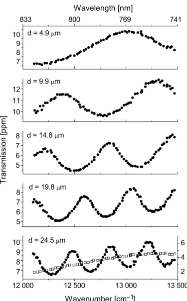
written using a focussed ion beam [52], each slit being 50µm long and 0.2µm wide. The centers of the slits are separated by a distance, as measured with a scanning electron microscope, of 4.9, 9.9, 14.8, 19.8 or 24.5 µm, respectively. Such a two-slit pattern, with the metallized side facing the laser, is illuminated at normal incidence with the well-collimated output beam (≈2 mm diameter) of a narrow-band CW Ti:sapphire laser, tunable between 740 and 830 nm. We detect in transmission, integrating the double-slit pattern over a large number of interference orders. The zeroth order peak is considerably stronger than the other orders, presumably as a result of non-negligible leakage through the bulk metal, and is therefore fully blocked by an opaque screen. We choose the polarization of the incident light to be either parallel (TE) or perpendicular (TM) to the long axis of the pair of slits.
2.4
Results
The results for the case of TM-polarization are shown in Fig. 2.1. The trans-mission is seen to be approximately sinusoidally modulated as a function of wave number, the modulation period being inversely proportional to the the slit separation. The visibility of the fringes is of order 0.2, roughly indepen-dent of the slit separation. Note that the fringes are superposed on an offset that gradually decreases as a function of wavelength.
When, instead, a TE-polarized beam is used to illuminate the double slit (24.5 µm slit distance) the detected signal shows no modulation whatsoever (see bottom frame of Fig. 2.1). Equally, no modulation is observed when the experiment is performed using a 200 nm thick titanium layer instead of gold, independent of the polarization of the incident radiation.
The observed strong polarization anisotropy and the dependence on the material of the screen both suggest that surface plasmons propagating along the gold/air interface lie at the heart of the observed phenomena. Alternative explanations in terms of waveguide modes within the slit [40, 41, 44, 45, 47] or diffractive evanescent waves [51] are excluded by the observed dependence of the spectral modulation period, and theindependenceof the modulation depth on the slit separation.
2.4 Results
Figure 2.2. Two interfering paths leading to light emission from the leftmost slit. A similar set of paths gives rise to emission from the slit on the right-hand side. The dashed line indicates the propagating surface plasmon.
constantksp of such a surface plasmon is given by [8]:
ksp=k0
md
m+d,
(2.1)
where m and d are the complex (relative) dielectric constants of the metal
and dielectric, respectively, andk0 = 2π/λ the free-space wave number. The
surface-plasmon wavelength is related to the real part of ksp by λsp=
2π/Re(ksp)≡λ0/nsp, while its (amplitude) decay length is given by 1/Im(ksp).
For the gold/air interface at λ0 = 800 nm nsp = 1.02 and 1/Im(ksp) ≈
80µm [53], considerably larger than the separation of the slits. Consequently, surface plasmons propagating along this interface can easily cover the distance between the slits. In contrast, the amplitude decay length for the Ti/air in-terface at λ0 = 800 nm is only ≈ 7 µm [54], considerably shorter than the
separation of most of our double slits. Surface plasmons launched on this in-terface simply do not survive long enough, as is confirmed by our experiments. Since the gold film is sandwiched between glass (d ≈2.1) and air (d= 1),
the surface plasmons living on the Au/air and Au/glass interfaces have differ-ent (complex) propagation constants (see Eq. (2.1)). Moreover, a 10 nm film of Ti lies between the glass substrate and the gold film, resulting in a much reduced decay length of the surface plasmons on that interface. Consequently, of all the interfaces that we probe in the experiment, only the Au/air vari-ety supports surface plasmons propagating over distances comparable to the separation of the slits.
Eslit(2)=E0(λ0)(1 +α(ksp) exp[i(kspd+ Φ)]), (2.2)
wheredis the slit separation,α(ksp) the relative strength of the plasmon
con-tribution and Φ a phase factor, assumed to be wavelength-independent. The field amplitude Eslit(2) behind the second slit is thus enhanced or suppressed, depending on the argument of the complex phase factor in Eq. (2.2). Be-cause our laser beam is normally incident on the sample and symmetrically illuminates the two slits, the field amplitude behind the first slit is given by Eslit(1) =E
(2) slit.
In the present experiment the far-field two-slit pattern arises as a conse-quence of the interference offourpaths, two of which are partially plasmonic, while the other two are photonic all the way. Although the number of inter-fering channels is four in the present experiment, the far-field pattern that arises behind the sample is simply that of Young’s experiment, i.e. a pattern of two interfering sources. The novel aspect is that the strength of each of these sources is enhanced or reduced due to the interference of a photonic and a plasmonic channel.
We collect a large number of interference orders on our detector thereby effectively erasing the far-field two-slit pattern. Hence, the signalS picked up by our detector is simply proportional to the total power radiated into the acceptance angle of the detector, i.e., to twice the power radiated by each slit separately,
S∝2E02(λ0)
1 +α2(ksp) + 2α(ksp) cos(kspd+ Φ)
. (2.3)
From the experiment we estimate that, across the wavelength range probed, the parameter α(ksp) ≈0.1 and is independent of the wavelength of the
inci-dent radiation. Further, in order to reliably fit our experimental transmission spectra with the expression given by Eq. (2.3) and the measured values for the slit separation we need to take the dispersion of the surface plasmon’s propa-gation constant into account. This provides additional support for our claim that the effect observed here is to be attributed to communication between the slits by propagating surface plasmons.
2.5 Theoretical calculation
Figure 2.3. The calculated transmission coefficient T of a double slit in a 200 nm thick gold film as a function of the wavelength of the inci-dent light. The slits are 200 nm wide and separated by 25.0µm. The full line displays the results for TM polarization, while the dotted line (magnified 10 times) shows the results for the case of TE polarization. The transmission coefficient is normalized to the area of the slits.
Note that for this polarization the incident light is beyond cut-off for each slit separately.
2.5
Theoretical calculation
Theoretically, we calculate the transmission of the double-slit system using a rigorous scattering model based on a Green’s function approach. We write the total electric field, E, as the sum of the incident field, E(inc), taken to be monochromatic and propagating perpendicular to the plate, and the scattered field, E(sca). The former is the solution of the scattering problem (including multiple reflections) in the absence of the slits, while the latter is the field due to their presence. The total electric field can be written as [55, 56]
E=E(inc)−iω∆
slits
G·Ed2r, (2.4)
where ∆=0−m is the difference in permittivity of the slits (vacuum) and
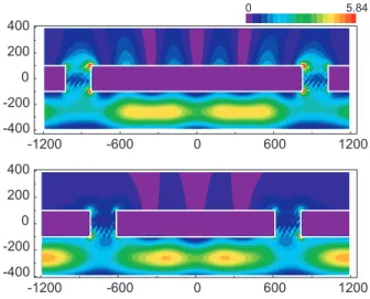
Figure 2.4. Intensity distribution in the immediate vicinity of the double-slit system for TM-polarized incident radiation when the trans-mission is maximum (top frame, slit separation equal to 5λsp/2), and minimum (bottom frame, slit separation equal to 4λsp/2)). The field is incident from below. All lengths are in nm.
The wavelength dependence of the dielectric constant of the gold film is fully taken into account [53].
In Fig. 2.3 the total transmission of the two-slit configuration is shown as a function of the wavelength of the incident radiation. When the incident field is TE polarized, the transmission of the double slit is small and weakly mod-ulated as a function of wavelength. In contrast, for a TM-polarized incident field, the transmission shows a strong modulation as a function of wavelength with a visibilityV ≈0.45. Overall the agreement between the experiment and the results of the Green’s function model is seen to be good, the theoretical data having a somewhat larger visibility than the experimental ones (V ≈0.2). This difference can be attributed to the different embedding of the gold film in the experiment and in the calculation. While in the experiment the gold film is asymmetrically encapsulated, in the calculation the materials at either side of the film are identical, greatly enhancing the plasmonic effects.
Using the theoretical model outlined above we have also calculated the intensity distribution, i.e. the value of |E|2, on both sides of a free-standing perforated gold film (see Fig. 2.4). For calculational convenience we have taken values of the slit separation that are considerably smaller than those of the experiment, viz. 5λsp/2, where the transmission is maximum, and 4λsp/2,
2.6 Conclusions
one can distinguish at the dark side of the metal film a well-developed standing wave pattern along the interface, having six antinodes, two of which coincide with the slits themselves. In contrast, when the transmission is minimum the antinodes of the standing-wave pattern do not coincide with the slits; at these locations one rather finds a node of the standing-wave pattern. In both cases the intensity is seen to rapidly decay away from the air-metal interface.
2.6
Conclusions
2.7
Appendix: Erasing the interference
(unpublished)In Chapter 2 we studied the transmission spectrum of a metallic film con-taining two close-lying sub-wavelength wide slits at normal incidence. The observed spectral modulation is explained in terms of plasmonic cross-talk, i.e., a coherent energy transport from one slit to the other by means of surface plasmons. Due to this process a fraction of the light incident on slit A emerges from slit B where it interferes with a fraction of the light incident on that same slit. This interference effect takes place in both slits and at normal incidence the relative phases of the two interfering channels in the two slits ∆φA and
∆φB are equal.
Here we study the transmission spectrum of such a double slit at non-normal incidence.
Figure 2.5. Experimental setup for measuring the transmission spec-trum of a double slit.
2.7 Appendix: Erasing the interference
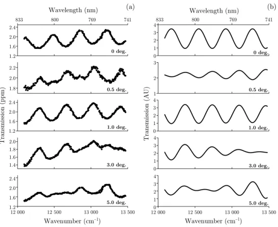
Figure 2.6. Experimental (a) and calculated (b) two-slit transmission spectra for angles of incidence of 0◦,0.5◦,1◦,3◦ and 5◦ (from top to bottom).
These observations can be explained by realizing that, at non-normal in-cidence, the relative phases ∆φA and ∆φB of the interfering channels in slits
A and B are no longer equal (see Fig. 2.7). The fields in the two slits can be written as:
EA = E0[1 +αexp{i(kspd+ Φ)}exp{i∆φ}], (2.5)
EB = E0[exp{i∆φ}+αexp{i(kspd+ Φ)}], (2.6)
where α is the surface-plasmon coupling coefficient and Φ a coupling phase, both of which are introduced in Chapter 2, and ∆φ =k0dsinψ is the extra
phase accrued by the light when traveling to slit B, with k0 the wave vector
The detector signalS(λ) can now be calculated1 by evaluating|EA|2+|EB|2,
S(λ) =S0[1 +α2+ 2αcos(kspd+ Φ) cos(k0dsinψ)]. (2.7)
It is seen that the term 2αcos(kspd+ Φ), describing the spectral modulation,
is itself amplitude modulated by the term cos(k0dsinψ). Whenever the latter
term goes to zero, the plasmon-induced spectral modulation is suppressed. Figure 2.6b shows the spectra according to Eq. (2.7) for α = 0.2 and Φ = π (see Chapter 5).
Figure 2.7. Pathways of light and surface plasmons when the sample is illuminated at an angle of incidence equal toψ.
We find good agreement between the calculated and observed modulation spectra. Note that the spectral modulation at an angle of incidence of 0.5◦ is calculated to be almost erased. This can be understood by evaluating the quantityk0dsinψ, which varies between 0.52πand 0.58πacross the wavelength
range studied so that cos(k0dsinψ) ≈ 0. The observed phase shift of the
modulation pattern upon changing the angle of incidence from 0◦ to 1◦ is due to the fact that k0dsinψgoes from 0 to ≈π.
Another way to look at the erasure phenomenon is by realizing that the spectral modulation originates in an interference phenomenon in each of the slits. The modulation being erased implies that, at the detector, the interfer-ence is made to vanish. By writing the signals from slits A and B as:
SA = S0[1 +α2+ 2αcos(kspd+ Φ + ∆φ)], (2.8)
SB = S0[1 +α2+ 2αcos(kspd+ Φ−∆φ)], (2.9)
we realize that the spectral modulation in SA is π out of phase with that in
SB whenever ∆φ=π/2 +mπ, withm an integer.
1A bucket detector is used to collect most of the interference orders such that the spatial
2.7 Appendix: Erasing the interference
Chapter 3
Enhanced spatial coherence by
surface plasmons
1We report on a method to generate a stationary interference pat-tern from two independent optical sources, each illuminating a single slit in Young’s interference experiment. The pattern arises as a result of the action of surface plasmons travelling between sub-wavelength slits milled in a metal film. The visibility of the interference pattern can be manipulated by tuning the wavelength of one of the optical sources.
1) N.V. Kuzmin, G. Gbur, H.F. Schouten, T.D. Visser, G.W.’t Hooft and E.R. Eliel,
3.1
Introduction
It is well known that the visibility of the interference fringe pattern observable in Young’s double-slit experiment is determined by the spatial and temporal coherence properties of the light incident on the slits [58]. For a stationary light field, these properties are described by the mutual coherence [58–60] function
Γ(P1, P2, τ) =E∗(P1, t)E(P2, t+τ), (3.1)
withE the complex amplitude of the field, assumed here to be scalar; P1 and
P2 denote the positions of the slits, τ a delay time, and the brackets a time
average. For our purpose it useful to employ the normalized mutual coherence function (the so-called complex degree of coherence), defined as
γ(P1, P2, τ) =
Γ(P1, P2, τ)
I(P1)I(P2)
, (3.2)
where I(Pi) is the averaged intensity at slit i. Under typical circumstances, the visibility V of the interference fringes near a point P in the far zone is equal to the modulus of the complex degree of coherence, i.e.
V =|γ(P1, P2, τ)|, (3.3)
withτ equal to the time difference (P1P−P2P)/c,cbeing the speed of light in
air. If one slit is illuminated by a light source radiating at frequencyω1 while
the other slit is illuminated by a separate source, radiating at frequencyω2, it
is easily seen that then γ(P1, P2, τ) = 0. Under these illumination conditions
the fringe visibility should thus be zero across the entire interference pattern for sufficiently long integration times.
3.2 Experiment
Figure 3.1. Sketch of the experimental setup. The outputs of a fiber-coupled diode and a Ti:sapphire laser are individually focussed on one of a pair of 200 nm wide slits, separated by ≈ 25 µm, in a thin gold film. The light diffracted at the two parallel slits is imaged onto a CCD camera. A = attenuator, M = mirror, BS = beam splitter,λ/2 = half-wave plate, P = polarizer, L = lens, and S = gold sample. The inset shows the illumination of the double slit.
3.2
Experiment
The experimental setup is shown in Fig. 3.1. Two separate lasers, a tunable narrow-band Ti:sapphire laser and a semiconductor diode laser operating at 812 nm, each illuminate a single sub-wavelength slit in a 200 nm thick gold film. Each laser is focused to a spot of approximately 5 µm FWHM. The two parallel slits,∼25µm apart, are 50µm long and 0.2µm wide. The gold film is evaporated on top of a 0.5 mm thick fused-quartz substrate with a 10 nm thick titanium adhesion layer between the gold and the quartz. A CCD camera is used to record the far-field pattern.
3.3
Results
When the polarization of the two beams is parallel to the two slits (TE po-larization), the resulting far-field pattern exhibits no fringes (see Fig. 3.2a), thereby confirming that the fields emerging from the two slits are completely uncorrelated (γ(P1, P2, τ) = 0). However, when the polarization is changed
to be perpendicular to the slits (TM polarization), a stationary interference pattern is obtained: γ(P1, P2, τ) = 0. This is shown in the bottom part of
Fig. 3.2, with a fringe visibility V = 20%. The fact that the appearance of interference depends on the polarization of the incident beams demonstrates that the interference phenomenon can not be attributed to one or both of the input beams illuminating the two slits to some extent.
Figure 3.2. (a) The far-field pattern for the case that both laser beams are TE-polarized (polarization parallel to the slits). The semiconductor laser emits at 812 nm while the Ti:sapphire laser is tuned to 808 nm. (b) The experimental far-field pattern when the polarization of both laser beams is perpendicular to the two slits (TM polarization). Large-period fringes with a visibilityV ≈20% are easily discerned. The arrow indicates the period of the fringes.
the mutual coherence (Eq. (3.1)) of the light fields incident on slit 1 and slit 2 is identical to zero, independent of the polarization. The fact that we, nevertheless, observe interference fringes for the case of TM-polarized illumination indicates that the fields emerging from slits 1 and 2 must, in that case, be at least partially mutually coherent. This mutual coherence is acquired by traversing the sample and, in view of the wavelength range of our study and the separation of the slits, we attribute it to the action of surface plasmons [8, 63]. Only when the incident light is TM polarized can they be excited at the slits. In the geometry of our sample they travel from one slit to the other with little loss, the slit separation (∼25µm) being smaller than their attenuation length (∼40 µm) [64]. At the second slit the surface plasmons are partially converted back into a propagating light field [34, 61]. The consequence is that, while we illuminate slit 1 with a laser operating at frequency ω1 and slit 2 with a laser operating at frequency ω2,both slits will
scatter at frequencies ω1 and ω2. Moreover, since the processes of scattering
free-space radiation into a surface plasmon and vice versa are phase coherent, the plasmon-mediated emission at frequency ω2 from slit 1 is fully coherent
with the direct emission by slit 2 at that frequency. Similarly, the plasmon-mediated emission by slit 2 and the direct emission by slit 1 at frequency ω1
3.3 Results
Figure 3.3. Interference patterns recorded with only a single slit illu-minated by the TM-polarized output of the Ti:sapphire laser for, from top to bottom,λ= 767 nm,λ= 775 nm andλ= 784 nm.
To corroborate the proposed explanation we have switched off one of the lasers so that only a single slit is illuminated (by a single laser). One then expects to again observe an interference pattern when the incident light is TM-polarized and none when it is TE-polarized. This is confirmed by the experiment, with Fig. 3.3 showing the results for the case of TM-polarized il-lumination. Here, the fringe visibility, of order 0.2, does not provide a measure for the phase correlation between the fields emitted by the two slits; it rather reflects the unbalance of the intensities of the fields emerging from the two slits (ratio ≈ 170). This unbalance can be tuned by adjusting the widths of the individual slits. High-visibility fringes are observed only when sub-wavelength slits as narrow as the ones of the current experiment (200 nm) are used.
Additional support for our interpretation in terms of surface-plasmon-enhanced spatial coherence comes from measuring the shift of the interference pattern upon changing the wavelength of the incident radiation. As shown in Fig. 3.3 we record the interference pattern for far-field angles ranging between 12◦ and 22◦, at the right side of the z-axis. If the left slit is illuminated and the wavelength is increased from 767 nm to 784 nm, the fringes shift to the left by approximately half a fringe, as shown in the figure. Actually, all the fringes that can be recorded shift to the left. However, when the right slit is illuminated, one observes that all the fringes shift to the right. This is not possible in a traditional Young’s-type experiment where the interference arises as a result of both slits being illuminated by a singlesource. In that case the pattern expands symmetrically around the z-axis.
Because the surface plasmon has to propagate from one slit to the other, the field emitted by the non-illuminated slit is delayed relative to that of the directly illuminated slit, the phase delay ∆φ(ω) being equal to
∆φ(ω) =ksp(ω)d+ψ. (3.4)
Hereksp(ω) is the surface-plasmon propagation constant,dthe slit separation,
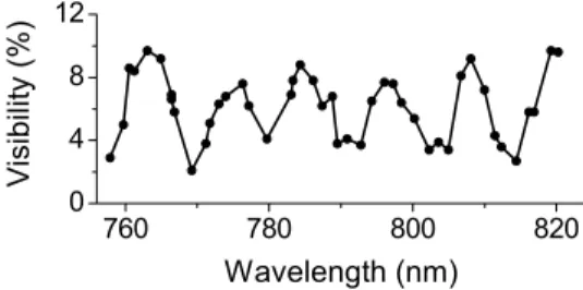
interfer-Figure 3.4. The fringe visibility of the recorded pattern (for TM-polarization) as a function of the wavelength of the Ti:sapphire lasers.
ence maximum is then given by
k0dsinθ±∆φ(ω) = 2πm, (3.5)
the sign depending on which slit is being illuminated. Here k0 represents the
free-space wave number of the incident radiation, andm is an integer. From this expression one calculates that the pattern shifts by half a fringe spacing for a wavelength change of 17 nm, in excellent agreement with the experimental result shown in Fig. 3.3.
In the case that both slits are illuminated (as in Fig. 3.2), albeit at differ-ent frequencies, we expect to observe anincoherent superposition of two fringe patterns. If ω1 and ω2 are not vastly different, as in the present experiment,
these patterns have very similar fringe spacings. However, because of the frequency-dependent phase delay of Eq. (3.4), these interference patterns can be aligned in different ways. In the case that the two patterns are perfectly aligned the observed interference pattern will have good visibility, while the visibility of the observed pattern can become close to zero when the two wave-lengths are chosen so that the nodes of the pattern at one frequency overlap with the antinodes of the pattern at the other frequency. Consequently, one expects the visibility of the fringe pattern to go up and down when tuning, for instance,ω1. Figure 3.4 shows our experimental results, taken in a setup using
3.4 Conclusions
3.4
Conclusions
Chapter 4
Bouncing surface plasmons
1Employing an interferometric cavity ring-down technique we study the launching, propagation and reflection of surface plasmons on a smooth gold-air interface that is intersected by two parallel, sub-wavelength wide slits. Inside the low-finesse optical cavity defined by these slits the surface plasmon is observed to make multiple bounces. Our experimental data allow us to determine the surface-plasmon group velocity (vgroup = 2.7±0.3 ×10⁻⁸ m/s at λ =
770 nm) and the reflection coefficient (R ≈ 0.04) of each of our slits for an incident surface plasmon. Moreover, we find that the phase jump upon reflection off a slit is equal to the scattering phase acquired when light is converted into a plasmon at one slit and back-converted to light at the other slit. This allows us to explain fine details in the transmission spectrum of our double slits.
1) N.V. Kuzmin, P.F.A. Alkemade, G.W. ’t Hooft and E.R. Eliel, Bouncing surface
4.1
Introduction
The observation by Ebbesen et al. [36] that a metal film that is perforated by a regular array of sub-wavelength holes transmits much more light than what is predicted by classical theory [37] has sparked a wide-ranging research effort into the physics of electromagnetic fields interacting with structured metal films. It is now broadly understood that surface plasmons (SPs) play a very important role in this transmission enhancement and this understanding has birthed a novel field of research commonly called “plasmonics”. Possible applications of plasmonics can be found in microscopy [65], bio-sensing [66,67], nano-optics [68, 69], nonlinear optics [70], cavity-QED [71] etc.
Although the transmission enhancement by surface plasmons in a metal hole array is dramatic, this 2D system is not optimal for studying the basic physics of scattering of EM radiation by perforations in metal films. Single sub-wavelength holes or slits in thin metal films provide more fundamental systems and their transmission has therefore received considerable attention, both the-oretically and experimentally [72]. An elegant extension to these basic systems is provided by the double slit, well known from Thomas Young’s landmark ex-periment; it has recently been shown that surface plasmons can give rise to a modulation of the transmission spectrum of the double slit [34, 35, 61, 73]. Furthermore, it has been reported that the spatial coherence of the light field behind such a double slit can be modified by the surface plasmons [74, 75]. In this type of experiments the sub-wavelength slit acts as an antenna — it scat-ters the incident radiation field into (Fig. 4.1a): i) a forward propagating field with emission angles ranging from −π/2 to +π/2; ii) a surface plasmon field travelling away from the slit along the metal-dielectric interface; iii) evanescent modes. A second, nearby slit can act as a receiver for the surface plasmon field and scatter it into, e.g., free space or into a backward-travelling/transmitted plasmon (Fig. 4.1b).
Incident light, that is coherently scattered into a plasmonic mode by one of the slits, can be re-radiated by the other slit, with a well-defined phase relationship with the light that is forward scattered by the latter slit; this explains the observed wavelength modulation of the transmission spectrum of the double slit [61].
4.2 Experiment
Figure 4.1. (a) The coupling of incident TM-polarized light into sur-face plasmons propagating along the metal-dielectric intersur-face on top, accompanied by direct transmission; (b) Incident surface plasmon out-coupling to free-propagating light, back-reflection and tunneling through the slit. Bottom interface is covered with metal (Ti) that suppresses sur-face plasmon propagation.
that travel up and down the cavity, displaying sharp structure when the waves make many round trips through the resonator, and shallow features when the number of round trips is small (of order 1). In conventional optical resonators this number depends on the loss per round trip [78]. There are two contribu-tions to this loss: internal loss due to extinction during propagation through the resonator (usually small or negligible in conventional optical resonators), and loss due to the finite mirror reflectivity or to diffractive losses at the edges of the mirror [78]. Both types of loss apply to our metallic resonator.
Here we report on time-domain measurements of the decay of the sur-face plasmon as it travels up and down a mesoscopic metallic resonator de-fined by sub-wavelength slits. These measurements yield data on the surface-plasmon group velocity, the reflection coefficient of a surface surface-plasmon for a sub-wavelength slit, and on phase jumps upon scattering and reflection.
4.2
Experiment
A conventional optical resonator is characterized by two parameters, namely the cavity round-trip time tax = L/vgroup and the cavity decay time τcav = −tax/ln(R), with R the mirror reflectivity. The former measures the time
it takes a pulse to make a round trip through the cavity of length L, while the latter equals the 1/edecay time of the intracavity power. The equivalent parameters in the frequency domain are the free spectral range ωax = 2π/tax
and thefinesse F; the finesse measures the ratio of the free spectral range and the cavity linewidth. Round-trip losses are the dominant factor that determine the finesse, and in conventional stable optical resonators the round-trip loss is usually determined by the reflectivity of the mirrors.
round-Figure 4.2. Experimental interferometer setup. The output of a wave-length tunable ultrashort pulsed Ti:sapphire laser, λ= 770–800 nm, is incident on a 50/50 beamsplitter (BS). The light reflects from two broad-band dielectric mirrors (M1,M2) and is recombined at the beamsplitter. Behind the sample (S) the light is detected by a Si photodiode detector (D). The pump-probe delay is varied by moving mirror M2.
trip losses are not only determined by the slit reflectivity but also by damping of the surface plasmon as it travels between the slits, due to the finite conduc-tivity of the metal film. By a judicious choice of the cavity length L we can tune the ratio of these two loss mechanisms. Measurements of the spectrum of a surface-plasmon resonator consisting of a smooth metal film bounded by two sub-wavelength slits demonstrate that its finesse is small (F ≈2) [61]. In that limit the finesse of a resonator is not a sensitive measure of the reflectivity as opposed to the case that the finesse is high, and requires experimental data with good signal-to-noise ratio. Note that if the finesse of a cavity is low it is not given by the well-known approximate expression F = π R1/2/(1−R),
but by F = π/{arccos[2R/(1 +R2)]} ≈ 2(1 + 4R/π). We therefore have chosen to measure in the time domain, essentially using a cavity ring-down technique [79].
4.3 Results
time will be of that same order of magnitude. Because of this ultra-short time scale traditional cavity ring-down techniques, where the power leaking through one of the cavity mirrors is monitored in real time [79], are not suited to the case of a SP cavity. Upconversion and autocorrelation techniques [81] provide alternatives here; the latter is used in the present work.
As a sample we use a 200 nm thick plane gold film attached to a fused-quartz substrate by a 10 nm thick titanium adhesion layer. The film is per-forated by two 50 µm long and 100 nm wide slits, separated by distances ranging from 25 to 90µm. The titanium adhesion layer is strongly dissipative to surface plasmons [61]; consequently the SPs that we study here are those of the gold-air interface.
We illuminate the sample by the output of a Michelson interferometer which, in turn, is illuminated by a short-coherence-length femtosecond tun-able Ti:sapphire laser (Fig. 4.2). We choose the polarization of the incident light to be perpendicular to the long axis of the slits (TM-polarization). The laser is operated at wavelengths around 770–800 nm, with a spectral width of ≈30–40 nm, yielding a coherence lengthcoh ≈16–20µm. The Michelson
interferometer serves to generate a time-delayed copy of the laser pulse and, together, these two pulses illuminate both slits of our sample. We image the double-slit output on a low-noise detector (New Focus model 2001-FS) and measure its output as a function of the delay ∆t between the two pulses in-cident on the sample. We collect the data on a computer using a 24-bit A/D converter (National Instruments PCI 5911) while slowly changing ∆t using a motorized translation stage (Newport model CMA-25CCCL). Note that our experimental approach is slightly unusual in that we send both the original pulse, henceforth called pump, and its copy, called probe, onto our sample, instead of illuminating the sample with just one of the pulses [82]. We have made this choice because of the large angular spread of the output of the sam-ple, its low transmission (typically 10−6 for a spot size of 50 µm diameter) and considerations of signal to noise.
4.3
Results
Figure 4.3. Experimental interferograms measured without sample (a) and with a sample containing a sub-wavelength slit pair with 25µm slit separation (b). The insets show details of the interference signal.
sample, using a double slit with a slit separation of 25 µm and TM-polarized incident light. The interference fringes show a quite different behavior here: most noticeably one observes the signal to partially recover after the initial collapse (peak B, Fig. 4.3b). This “echo” has an amplitude of order 10% of the initial signal. Upon careful observation one notices that the signal goes through an additional cycle of collapse and recovery (peak C). When the po-larization of the incident light is chosen to be TE, we observe no revivals; the signal is indistinguishable from that measured with the double slit absent (Fig. 4.3a).
As we will argue below, the first echo (B) comes about because surface plasmons are launched at the slits, travel from one slit to the other, to arrive there after a delay ∆t; the second, weaker, echo (C) arises because a surface plasmon that is launched at one of the slits, can be back-scattered by the other slit to return to its place of birth with a delay equal to 2∆t.
4.4 Discussion
Figure 4.4. Carrier envelopes of the demodulated experimental signal for samples with slit separation equal to 25 µm (a) and 50 µm (b), respectively.
plot, on a logarithmic scale, in Fig. 4.4a. Here we see that the signal contains
five interference maxima (peaks A–E), spanning four decades of signal. The interference maxima are equidistant with a peak-to-peak separation of 93 fs. The two additional peaks that show up in the carrier envelope (D,E) are then identified with the case that a surface plasmon is back-scattered twice and
three times, respectively. Altogether, the surface plasmon is seen to make two full round trips through the cavity. Figure 4.4b shows the carrier envelope for the case that a double slit with a slit separation of 50 µm is studied. Here we observe essentially the same features as before, except that, naturally, the subsidiary maxima are farther apart and thus better resolved.
4.4
Discussion
The experimental data of Fig. 4.4 give direct access to some important ex-perimental parameters, i.e., the SP group velocity vgroup, the complex SP
Figure 4.5. (a) Delay between peaks A (direct transmission) and B (representing the surface plasmon wavepacket) for different slit separa-tionsL. The slope of the line through the points determines the value of 1/vgroup; (b) Ratio of the second to first peaks (B/A) as a function of the slit separationL; (c) Ratio of the third to second peaks (C/B) for different values of the slit spacing.
group-velocity dispersion of the SP is small or negligible, the group velocity can be determined directly from the separation between subsequent peaks in the signal envelope. Bothvgroup and its dispersion can be calculated from the
dispersion relation of the SP travelling along the plane interface between a metal and a dielectric [8],
ksp(ω) = ω
c
m(ω)d(ω)
m(ω) +d(ω),
(4.1)
withm(ω) andd(ω) the dielectric coefficients of the metal and the dielectric,
respectively. We use the tabulated values form(ω) [53] and setd(ω) = 1, the
dielectric being air. Atλ= 770 nm we calculatevgroup= dω/dksp 2.72×10⁸
m/s and a value for the group velocity dispersion d2ksp/dω2 0.76 fs2/µm
equivalent to a group delay dispersion d(vgroup−1 )/dλ −2.4 as/nm·µm. For the
experiment with a slit separation of 50µm and the pulse spectral width ∆λ= 27 nm (corresponding to a Fourier-limited cosh−1 pulse duration of 32 fs) the group delay dispersion leads to a pulse broadening of only 5 fs and can therefore be neglected. It is therefore perfectly allowed to extract an experimental value of the SP group velocity directly from the separation between successive peaks in the interferogram (Fig. 4.5a), provided that they are well separated, as in the case of 50 µm slit separation. This yieldsvgroup= 2.70±0.03×10⁸ m/s.
This result is in excellent agreement with the calculated value and with [73], in contrast to the findings of Baiet al. [83]. An experimental indication that effects of group velocity dispersion are indeed small comes from the observation that all peaks in the interferogram have the same width.
4.4 Discussion
on both the absolute value of the light→SP→light coupling coefficientα and of the SP reflection coefficient r. The peak-height ratio (B/A) of the first echo and the peak at zero delay is given by |α|exp(−kspL), while that of the
second and first echo’s (C/B) is given by|r|exp(−kspL). By determining these
peak-height ratio’s from measurements performed on double-slit systems with different inter-slit separations L, and plotting these ratio’s on a logarithmic scale versus L, as shown in Fig. 4.5, we can extract |α|and |r|from the line intercepts andkspfrom the slope of the lines. This yields|α|= 0.19±0.02,|r|=
0.18±0.01 andksp = 0.02µm−1. The damping constant is approximately twice
the value that one calculates from the surface-plasmon dispersion relation (Eq. (4.1)) using Palik’s data for the dielectric coefficient of gold [53]. We attribute the additional damping to the fact that our gold film has deteriorated over a period of a year of use, giving rise to scattering loss in the film. The value for α is in good agreement with the prediction by Lalanne et al. [34]. The intensity reflection coefficientR=|r|2of the slit is quite small (R ≈0.04);
consequently the cavity finesse is very small: F = 2.1. Similar values for the reflection coefficients from edges and subwavelength-wide groves and barriers have been reported [84–89].
The interferogram is also sensitive to the phase of both α and r, and to illustrate that point we return to the resonator picture discussed earlier. The output of the “resonator” consists of a sequence of pulses, the first one (A) simply being the light directly transmitted through the slits, the second (B) due to the SP being excited at one slit and scattered back into light at the other slit, the third (C) due to the reflected SP being back-scattered into light at the first slit, etc. The transfer functionG(ω) of the double slit can thus be written as:
G(ω) = 1 +αexp[ikL] +αrexp[2ikL] +αr2exp[3ikL] +· · · , (4.2)
= 1 + αexp[ikL]
1−rexp[ikL], (4.3)
withk=ksp(ω) the complex surface-plasmon wave vector (see Eq. (4.1)); here
the coefficientsα andrare assumed to be frequency independent. In the limit thatr= 0 this transfer function gives rise to a sinusoidally modulated two-slit spectrum [61], showing maxima wheneverkL+ arg(α) = 2πm, withminteger. Various theoretical studies suggest that arg(α) =π [34, 61, 90].