Research Article
a
April
2018
Special Issue: National Conference on Emerging Trends in Engineering 2018
Conference Held at Sri Venkatesa Perumal College of Engineering & Technology, Puttur, A.P., India
Computer Science and Software Engineering
ISSN: 2277-128X (Volume-8, Issue-4)
Static Analysis of a Primary Suspension Spring Used in
Locomotive
S. Praveen Kumar N. Rajesh P V Divakar Raju
Assistant Professor Associate Professor Assistant Professor
Department of ME, C.R. Engineering College
Department of ME, C.R. Engineering College
Department of ME, C.R. Engineering College
Tirupati-517506, India. Tirupati-517506, India. Tirupati-517506, India.
[email protected] [email protected] [email protected]
Abstract: A spring is an elastic object used to store mechanical energy. They can twist, pulled or stretched by some force and can return to their original shape when the force is released. Static analysis determines the safe stress and corresponding pay load of the helical compression spring. The present work attempts to analyze the safe load of the locomotive suspension spring with different materials. A typical locomotive suspension spring configuration is chosen for study. In this present work is carried out on modeling and analysis of primary suspension spring (60Si2MnA) is to replace the earlier conventional steel helical spring (Chrome Vanadium). The work is to reduce the overall stress and deflections of the helical spring by using the new material. This work describes static analysis of the locomotive suspension spring is performed using Ansys 14.0 and compared with analytical results. The spring model is done by using Pro/E Wildfire 4.0 software.
Keywords: Locomotives, Primary suspension system, Helical spring, Modeling, Static analysis, Ansys 14.0, Pro E-4
I. INTRODUCTION
Locomotives are one of the primary transport systems for all classes of people. Mainly a train is divided into two parts one is bogie and compartment. Lower part of the train is known as bogie and upper part of the train is known as compartment. In this study, locomotive primary suspension spring is chosen for analysis. The calculation, design and testing of spring suspension as an important component of the bogie represent a complex and high engineering task.
II. PRIMARY SUSPENSION SYSTEM
The natural progression from the rigid framed vehicles used in the early days of European railways to a bogie vehicle brought with it a more sophisticated suspension system. This system was based on a steel plate framed bogie with laminated spring axle box suspension, much as seen on the first vehicles, and with a secondary suspension added between the car body and the bogie. First, we look at the primary suspension.
The diagram above shows a plate framed bogie with the primary, axle box suspension.
ISSN(E): 2277-128X, ISBN: 978-93-87396-07-4, pp. 294-298
The weight of the bogie on the axle box is transmitted through the steel laminated spring and the two spring hangers. Each spring hanger and its associated spring carry 1/16th of the total car weight. The height of the bogie relative to the rail level could be adjusted by using the screwed spring hangers. The adjustment allowed for small variations in wheel diameter.
SPRINGS
Springs are elastic bodies (generally metal) that can be twisted, pulled, or stretched bysome force. They can return to their original shape when the force is released. In otherwords it is also termed as a resilient member. Based on the shape behavior obtained bysome applied force, springs are classified into the following ways:
• Helical springs • Leaf springs
HELICAL COMPRESSION SPRING
The gap between the successive coils is larger.
• It is made of round wire and wrapped in cylindrical shape with a constant pitch between the coils. • By applying the load the spring contracts in action.
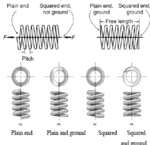
• There are mainly four forms of compression springs as shown in Figure 3.
They are as follows:
• Plain end• Plain and ground end• Squared end• Squared and ground end
Among the four types, the plain end type is less expensive to manufacture. It tends to bow sideways when applying a compressive load.
Applications
• Ball point pens• Pogo sticks• Valve assemblies in engines
Figure 3: Compression Helical Spring
III. SPECIFICATION OF HELICAL COMPRESSION SPRING
Existing Spring(Chrome Vanadium)
Profile and Material Properties of primarysuspension spring:
Dimensions for spring
Table 1: Dimensions of Helical Spring
S.No Description Dimension Value
1 Wire dia. (d) 33.5 mm 2 Outer Dia (Do) 244.5 mm 3 Mean Dia (D) 211 mm 4 Free Height (Hf) 360 mm
5 Test Load (W) 19.6 KN (on each spring) 6 No. of Active Coils (n) 8
ISSN(E): 2277-128X, ISBN: 978-93-87396-07-4, pp. 294-298 Table 2: Chemical Composition
C Mn P S Si Cr
0.48-0.55 0.65-0.90 0.04 max 0.04 max 0.20-0.35 0.80-1.0
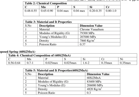
Table 3: Material and It Properties
S.No Description Dimension Value
1 Material Chrome Vanadium
2 Modulus of Rigidity (G) 79300 MPa 3 Young’s Modulus (E) 207000 MPa
4 Density 7860 Kg/m3
5 Poisson Ratio 0.37
Proposed Spring (60Si2MnA)
Table 4: Chemical Composition of (60Si2MnA)
C Mn P S Si Cr Ni
0.56-0.64 0.7-1 0.025max 0.025max 1.6-2 0.35max 0.35max
Table 5: Material and It Properties(60Si2MnA)
S.No Description Dimension Value
1 Material 60Si2MnA
2 Modulus of Rigidity (G) 83600 MPa 3 Young’s Modulus (E) 206000 MPa
4 Density 4820 Kg/m3
5 Poisson Ratio 0.3
ANALYTICAL CALCULATIONS OF HELICAL SPRING Calculation Part (Existing System)
Maximum shear stress τ = K 8WD
πd3
Wahl’s stress factor =4C − 1
4C − 4+
0.615 C
C =D
d=
211
33.5= 6.3
Now k = 1.24
𝝉 = 𝟏. 𝟐𝟑 ∗ 𝟖 ∗ 𝟏. 𝟗𝟔 ∗ 𝟏𝟎
𝟑∗ 𝟐𝟏𝟏
𝝅 ∗ 𝟑𝟑. 𝟓𝟑
Maximum shear stress 𝝉= 347.34 MPa
Deflection
Deflection of the spring(δ) = 8WD
3n
Gd4
𝜹 = 𝟖 ∗ 𝟏𝟗𝟔𝟎𝟎 ∗ 𝟐𝟏𝟏
𝟑∗ 𝟔. 𝟕𝟓
𝟕𝟗𝟑𝟎𝟎 ∗ 𝟑𝟑. 𝟓𝟒
= 99.55 mm
Calculation Part (Proposed System) Deflection
Maximum shear stress τ = K 8WD
πd3
Wahl’s stress factor =4C − 1
4C − 4+
0.615 C
C =D
d=
211
33.5= 6.3
Now k = 1.24
𝝉 = 𝟏. 𝟐𝟑 ∗ 𝟖 ∗ 𝟏. 𝟗𝟔 ∗ 𝟏𝟎
𝟑∗ 𝟐𝟏𝟏
𝝅 ∗ 𝟑𝟑. 𝟓𝟑
ISSN(E): 2277-128X, ISBN: 978-93-87396-07-4, pp. 294-298 Deflection
Deflection of the spring(δ) = 8WD
3n
Gd4
𝜹 = 𝟖 ∗ 𝟏𝟗𝟔𝟎𝟎 ∗ 𝟐𝟏𝟏
𝟑∗ 𝟔. 𝟕𝟓
𝟖𝟗𝟑𝟎𝟎 ∗ 𝟑𝟑. 𝟓𝟒
= 94.43 mm
IV. FINITE ELEMENT ANALYSIS
FEA consists of a computer model of amaterial or design that is stressed andanalyzed for specific results. It is used in newproduct design, and existing productrefinement. A company is able to verify aproposed design will be able to perform to theclient’s specifications prior to manufacturingor construction. Modifying an existing productor structure is utilized to qualify the product orstructure for a new service condition. In caseof structural failure, FEA may be used to helpdetermine the design modifications to meetthe new condition.
There are generally two types of analysisthat are used in industry: 2-D modeling, and3-D modeling. While 2-D modeling conservessimplicity and allows the analysis to be run ona relatively normal computer, it tends to yieldless accurate results. 3-D modeling, however,produces more accurate results whilesacrificing the ability to run on all but the fastestcomputers effectively. Within each of thesemodeling schemes, the programmer can insertnumerous algorithms (functions) which maymake the system behave linearly or nonlinearly.Linear systems are far less complexand generally do not take into account plasticdeformation. Non-linear systems do accountfor plastic deformation, and many also arecapable of testing a material all the way tofracture.
V. ANALYSIS OF BOTHHELICAL SPRINGS
A static analysis calculates the effects of steady loading conditions on a structure, while ignoring inertia and damping effects, such as those caused by time-varying loads. A static analysis can, however, include steady inertia loads (such as gravity and rotational velocity), and time-varying loads that can beapproximated as static equivalent loads (such as the static equivalent wind and seismic loadscommonly defined in many building codes). Static analysis is used to determine thedisplacements, stresses, strains, and forces in structures or components caused by loadsthat do not induce significant inertia and damping effects. Steady loading and responseconditions are assumed; that is, the loads andthe structure’s response are assumed to varyslowly with respect to time.
VI. RESULTS
The above results shows that the 60Si2MnA is best replacement of Chrome Vanadium and the deflection and stress induced are very less comparative.
Figure 4: 3D Model of Spring Figure 5: Mesh of Primary Suspension Spring
ISSN(E): 2277-128X, ISBN: 978-93-87396-07-4, pp. 294-298
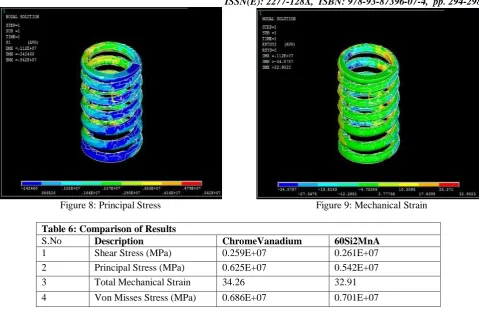
Figure 8: Principal Stress Figure 9: Mechanical Strain
Table 6: Comparison of Results
S.No Description ChromeVanadium 60Si2MnA
1 Shear Stress (MPa) 0.259E+07 0.261E+07 2 Principal Stress (MPa) 0.625E+07 0.542E+07 3 Total Mechanical Strain 34.26 32.91 4 Von Misses Stress (MPa) 0.686E+07 0.701E+07
VII. CONCLUSION
From the above analysis, even though the stresses are almost equal, but the deflection of suspension spring is less when comparative to the Chrome Vanadium and it will works efficiently with less maintenance.
Due to the placing of 60Si2MnA steel maintenance can be reduced. The cost60Si2MnA steel material is cheaper in India and international markets compare to Chrome Vanadium.
REFERENCES
[1] Valsange P S (2012), “Design of Helical Coil Compression Spring: A Review”,International Journal of Engineering Research and Applications, ISSN: 2248-9622.
[2] Research Committee on the Analysis of Helical Spring, Transactions of JapanSociety for Spring Research, No. 49, p. 35 (2004).
[3] PriyankaGhate, Shankapal S R and Monish Gowda M H (2012), “FailureInvestigation of A Freight Locomotive Suspension Spring and Redesign of theSpring for Durability and Ride Index”, Automotive and AeronauticalEngineering, Dept. M.S. Ramaiah School of Advanced Studies, Bangalore 560058.
[4] L. Del Llano-Vizcaya, C. Rubio-Gonzalez &G.Mesmacque (2007), “Stress relief effect on fatigue and relaxation of compression springs”, material and design, vol.28, pp.1130-1134.