Grid Connected Single Phase Rooftop Pv System With Limited
Reactive Power Supply
Tota Sankara Rao1, Smt.N.Sirisha2
1PG Scholar, Pydah College of Engineering, Kakinada, AP, India. 2Associate Professor, Pydah College of Engineering, Kakinada, AP, India.
Abstract- In this paper SRF theory based PV system with MPPT DC-DC controller for grid connected single phase rooftop system have been presented. Photovoltaic (PV) systems are the alternative source of generation because these can be placed near to the load centers when compared with other renewable source of generation. The rooftop PV system in general is grid connected and supports the off grid load with battery backup. It is therefore rooftop PV is the centre of attraction for majority PV systems. The proposed system must ensure total evacuation of generated power and with high efficiency of conversion, and utilizes the resource adequately to maximize the utilization of energy. The voltage source converter (VSC) will operate based on the PWM controller to realize maximum generated power evacuation by maintaining the DC link voltage as a constant value without any battery storage system, low THD sinusoidal line synchronized current output, and also limits the reactive power and controls the power actor based on the unutilized capacity of the inverter. This paper proposes SRF theory based PV system with
MPPT DC-DC PWM controller. Incremental
conductance (IC) method is used to get maximum power from the PV system. The simulation results shows the efficient working of rooftop PV with proposed control algorithms in grid connected mode using MATLAB/ SIMULINK software.
Index Terms- MPPT, Synchronous reference frame (SRF), Incremental Conductance (IC), Photovoltaic (PV)
I. INTRODUCTION
The major utilization of these sources with grid
integration is the challenging task. It is therefore
Distribution Generation (DGs) particularly single phase rooftop PV system are major research area for grid integration, since these sources have huge opportunity of generation near load terminal. World is moving towards the greener sources of energy to make the planet pollution free and environment friendly. The rooftop application involving single phase DG’s fed with PV source can be not only utilized for household use but the excess energy can be transferred to the grid through proper control scheme and adequate hardware. Control scheme based on instantaneous
PQ theory has been presented in some literatures for single phase system. Other control scheme such as synchronous reference frame (SRF) is mainly used with three phase system in which sinusoidal varying quantities are being transferred to dc quantities that provides better and precise control than PQ based control even under distorted condition of mains. But SRF based control scheme can be customized for single phase which can’t be utilized to get the desired dc quantity to generate required reference command. PV sources are interfaced with the grid through voltage source converters (VSC’s).
VSC’s can be controlled either in PWM based voltage control method or hysteresis based current controlled method (HCC). HCC based controller gives fast response and better regulation but its major drawback lies with variable frequency. On the other hand the PWM based control gives fixed switching frequency that could be utilized easily for proper design of LC or LCL filters. With PV sources connected at the DC side of the inverter, it is utmost essential to fetch maximum power from the source to make the system efficient. Out of different algorithm to track maximum power point (MPP) such as perturb and observe (P&O), Incremental Conductance (IC) etc., IC based method provides fast dynamics and control over fast changing insolation condition. In this paper new control scheme based on SRF theory has been proposed for single phase rooftop PV grid connected system.
II. SYSTEM CONFIGURATION
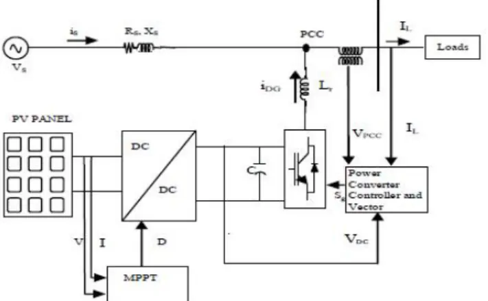
Fig.1 depicts the schematic diagram of single phase grid connected PV system comprising PV panels, DC-DC converter, MPPT charge controller, tank capacitor, VSC and RL loads. IC based MPPT controller is used to extract the maximum available power from the PV panels. Control based on tank capacitor voltage is used to control the transfer of maximum power to the grid via VSC. The direct voltage controlled current driven VSC keeps the voltage across the tank capacitor constant by regulating the power evacuation through voltage control. Proper design of LCL filter at the output of VSC filters out harmonics at the PCC. The conventional 3 phase SRF theory is modified to suit the single phase system. The modified SRF theory is applied to decompose the load current to generate the reference reactive power current command. Reference for the real current component is obtained by applying PI controller on the error between measured voltage and the reference voltage.
Fig. 1Block diagram for system configuration of PVDGCC
III. MODELING OF PV ARRAYS
The basic equations that govern I-V characteristic of the ideal photovoltaic cell are reported in literatures. The typical equation governing the PV arrays is given by (1)
Ns-Number of cells connected in series; Rp=Equivalent
parallel Resistance; Rs= Equivalent contact series
Resistance. Commercially available KC200GT Kyocera make PV panels are considered here to design the array to deliver power of 800W by connecting 3 panels in a string and similar 2 strings in parallel in MATLAB Simulink. The parameters of the panel are shown in Table I. The proposed charge controller operates to extract the maximum power at
one level of solar insolation by using Incremental
Conductance based MPPT controller.
Fig 2 PV panel Model
IV. CONTROL THEORY
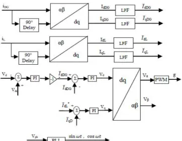
The proposed system the 3 phase SRF based theory is modified for single phase system. The heart of the control scheme lays with correct estimation of phase voltage though phase locked loop (PLL), which is used for generation of unit template vectors. The output of the PLL will be in phase with single phase voltage at PCC. For applying modified SRF theory to single phase system, phase voltage or current is assumed as alpha (α) component in α-β frame (stationary frame of reference), and β component is obtained by introducing phase delay of 90° to alpha components as shown in Fig. 3. Using modified SRF theory both DG and load currents are transformed into d-q components and passed through low pass filter (LPF) to obtain only DC components corresponding to fundamental frequency as shown in Fig. 3. For such synchronized modified SRF theory based transformation and components corresponds to real and reactive power components respectively.
TABLE I
PARAMETERS OF THE KYOCERA MODEL KC200GT SOLAR ARRAY AT NOMINAL
OPERATING CONDITIONS
Id and Iq obtained through transformation is passed though LPF to obtain the at DC quantities which after proper control on this DC quantity, it’s again converted back to α-β component.
is required to be maintained across DC link capacitor, and reference current is generated to obtain the command voltage reference for PWM control of the VSC as shown in Fig. 3. The control forces the output current of VSC to closely follow the reference current.
The DG’s main task is to send maximum power to the grid via VSC. In the event of varying insolation or during low insolation, the VSC capacity is not fully utilized for real power transfer. The unutilized capacity can be used for limited reactive power compensation. The depth of
compensation is based on capacity remaining after
deducting MPPT tracked PV power from the total capacity of VSC. In view of this reactive power component in load is determined and multiplied with ‘k’ showing the selective or amount of power to be compensated as shown in Fig. 3. This reference reactive command is compared with DG ‘ qDG’ component and error is passed through PI controller to generate reference Vq*component. This voltage reference d-q component is then reverse transformed to α-β using equations (8). Out of the two components in stationary frame of reference vα* component is used for PWM gating signal generation.
Fig. 3.Control Scheme for proposed System
LCL filter design:
Fig. 4 shows the LCL filter which is placed at the VSC output terminal to get the filtered output. Proper design of filter is crucial from the stability point of view. Applying KCL to the LCL circuit following equations are synthesized:
Fig. 4 LCL model
Using above equations (6) - (10) circuit can be modeled as block diagram as shown in Fig. 5. For checking the stability of the filter design bode plot is drawn in the MATLAB for the parameters given in table II as shown in Fig. 6. From Fig. 6 it can be seen that the plot have overshoot near resonant frequency other plot with low damping and other with proposed system of LCL filter parameters show no overshoot and proper damping. The adequate passive damping provided avoids peak at resonant point and prevents loss of gain, by appropriately choosing the damping ratio. By keeping L1 and L2 same, reactive interaction of filter capacitance gets minimized with the line with minimized value of capacitance.
Fig. 5 Block diagram representation of LCL filter
V. SIMULATION RESULTS
The complete single phase grid connected PV system is simulated under MATLAB simulink with RL load (R= 4 Ω, L = 4 mH) as shown in Fig.7. PV panels are connected in series and parallel in such a way that array
insolation level. IC based MPPT algorithm is verified by writing embedded MATLAB code. LCL filter is connected at the output of VSC as per parameters given in the table II.
The simulated results are studied to compute the
performance of single phase grid connected system under limited available capacity of VSC. The parameters of the considered system are shown in Table-III.
Fig 6 simulation diagram of single phase system
Fig 7 simulation diagram of proposed system with PV
Fig 8 simulation diagram of SRF controller for the proposed system with PV
Fig 9 waveforms of PV power, VSC converter, active & reactive powers, power factor and irradiance of PV system
Fig 10 waveforms of source voltage, source current and load current
Fig 11 10 waveforms of source voltage, source current load current and DG system current
Fig 12 waveforms of active & reactive powers and power factor
CONCLUSION
estimation is employed which provides rugged control with cost effective solution. The proposed SRF based approach enable the control for providing limited compensation of reactive power depending on available unutilized capacity of VSC. The implemented scheme derives the advantage of simplicity and is capable of delivering under varying insolation conditions effectively. Such technique is envisaged to benefit the PV rooftop system and grid/micro-grid by the limited compensation.
REFERENCES
1. Velasco de la Fuente, D. ; Garcera, G. ; Figueres, E. ; Guacaneme, J. “Reconfigurable control scheme for a PV microinverter working in both grid connected and island modes,” IEEE Trans. Industrial Electronics, 2012.
2. Jmjun Liu ;Jun Yang ;Zhaoan Wang "A New Approach For Single- Phase Harmonic Current Detecting And Its Applicationin in a Hybrid Active Power Filter," IEEE conf., 1999.
3. B. Singh, V. Verma, “,Selective compensation of power-quality problems through active power filter by current decomposition”IEEE Trans. Power delivery., vol. 23, no. 2, April 2008.
4. Guohong Zeng; Rasmussen, T.W.; Lin Ma; Teodorescu, R., “Design and of LCL-filter with active damping for Active Power Filter,” IEEE International Symposium on Industrial Electronics, pp. 2657-2562, 2010.
5. S.Mekhilef, "Performance of grid connected inverter with maximum power point tracker and power factor control," International Journal of Power Electronics, vol. 1, pp. 49-62, 2008.
6. S.Mekh Femia, N.; Petrone, G.; Spagnuolo, G.; Vitelli, M., “A Technique for Improving P&O MPPT Performances of Double-Stage Grid-Connected Photovoltaic Systems,” IEEE Trans. Industrial Electronics, vol. 56, pp. 4473-4482, 2009.
7. M. G. Villalava,j. r. Gazoli,E. Ruppert F., “Modelling and circuit –based simulation of Photovoltaic arrays” Brazilian Journal of Power Electronics,vol 14,no.4,pp. 35-45, 2009 8. B. Crowhurst, E.F. El-Saadany, L. El Chaar and L.A. Lamont "Single- Phase Grid-Tie Inverter Control Using DQ
Transform for Active and Reactive Load Power