Interference Management in LTE-Advanced
Heterogeneous Network
School of Electrical Engineering
Thesis submitted for examination for the degree of Master of Science in Technology.
Espoo 15.5.2015
Thesis supervisor:
Prof. Risto Wichman
Thesis advisor:
Author: Geethu Vijayaraghavan
Title: Interference Management in LTE-Advanced Heterogeneous Network
Date: 15.5.2015 Language: English Number of pages: 8+51
Department of Signal Processing and Acoustics Professorship: S-88 Signal Processing
Supervisor: Prof. Risto Wichman
Advisor: M.Sc. (Tech.) Pramod Mathecken
In this thesis, we consider the problem of interference management in heterogeneous networks which is one of the main features proposed in long term evolution advanced (LTE-Advanced) communications standard. The network architecture of heterogeneous network consists of a main cell coexisting with different types of smaller cells. Heterogeneous networks are one cost effective way of handling the unrelenting data traffic demand. The major technical challenge associated with this type of network architecture is the interference experienced between coexisting cells. Interference can be either between similar type of cells or between different types of cells within the network area. In this thesis, we consider a heterogeneous network with a macro cell coexisting with a femto cell. The interference between the cells will lower system performance and eventually result in poor macro user experience. Among the various enhanced intercell interference coordination (eICIC) techniques proposed in the third generation partnership project (3GPP), we focus on power control and time domain schemes using almost blank subframes (ABS). However, these interference management schemes reduce the throughput of femto cell users. This necessitates the need to optimize the resources of power and ABS transmission so that interference experienced by macro user is low and throughput of femto user is high simultaneously. Hence, we consider a joint optimization problem to find the optimal value of power and number of ABS transmission required at the femto cell. In previous work, these optimal parameters were obtained for a system with a macro base station (MBS) serving only one macro user in downlink. We extend the analysis to determine optimal parameters when MBS serves multiple macro users. Specifically, we show that the optimal parameters of power and number of ABS transmissions obtained for the macro user closest to the femto base station (FBS) guarantees maximum throughput for the femto user and minimal interference for all other macro users.
Keywords: eICIC, ABS, power control, macro cell, femto cell, heterogenous network, interference management, capacity, macro user, femto user.
Preface
The journey to the completion of this thesis work has been eventful and marked with contributions from lots of people. Foremost, I thank God almighty for giving me strength to complete this thesis. I am immensely grateful to Prof. Risto Wichman for giving me an opportunity to work under him and for the valuable guidance he has given during the period of the project. I am very much indebted to M.Sc (Tech) Pramod Mathecken my thesis advisor, who guided me through each and every step of this thesis. I am extremely humbled by the way you guided and supported me.
I would also like to thank my family back home and my friends in Finland for their unconditional love and care.
Otaniemi, 15.5.2015
Contents
Abstract ii
Preface iii
Contents iv
Symbols and abbreviations vii
1 Introduction 1
1.1 Research Problem and Scope. . . 1
1.2 Contributions of the Thesis . . . 2
1.3 Thesis Structure. . . 2
2 Chapter 2 4 2.1 Long Term Evolution (LTE) . . . 4
2.2 Features Of LTE-Advanced. . . 5
2.2.1 Carrier Aggregation. . . 5
2.2.2 Multiple-input and Multiple-out . . . 5
2.2.3 Coordinated Multipoint . . . 5
2.3 Homogeneous Cellular Network . . . 6
2.3.1 Macro cell . . . 6
2.4 Heterogeneous Network. . . 7
2.4.1 Pico cell . . . 8
2.4.2 Relays . . . 8
2.4.3 Remote Radio Head (RRH) . . . 8
2.4.4 Femto cells . . . 8
2.5 Technical challenges in heterogeneous network . . . 10
2.5.1 Self-Organising Networks . . . 10
2.5.2 Backhauling . . . 10
2.5.3 Mobility Management and Handover . . . 11
2.6 Intertier and Intratier Interference . . . 11
2.7 Interference Management Techniques . . . 12
2.7.1 Frequency Domain Techniques . . . 13
2.7.2 Time Domain Techniques . . . 16
2.7.3 Power Control Techniques . . . 19
2.8 Summary . . . 20
3 Interference Management In Heterogeneous Network 21 3.1 System Model for Heterogeneous Network . . . 22
3.2 Intertier Interference . . . 22
3.3 Enhanced Intercell Interference Coordination Techniques (eICIC) . . 23
3.3.1 Time Domain Interference Management using ABS . . . 23
3.3.2 Interference Management by Power Control . . . 24
3.5 Rate Analysis using eICIC Techniques . . . 25
3.6 Problem Motivation. . . 26
3.6.1 Without Interference Management (WIM) . . . 27
3.6.2 Single Level Power Control (SLPC) . . . 27
3.6.3 Joint Power and ABS Control using Noninteger L . . . 27
3.6.4 Joint Power and ABS Control Optimization with Integer L . . 28
3.7 Simulation Results . . . 30
3.8 Conclusion . . . 32
4 Interference Management with Multiple Macro Users in Downlink 33 4.1 System Model with Multiple Macro Users . . . 33
4.2 Interference Management. . . 34
4.3 Optimization Problem for Interference Management . . . 34
4.4 Equivalence of (P:) and (S:) . . . 35
4.4.1 Case 1 . . . 35
4.4.2 Case 2 . . . 37
4.5 Special Case: Multiple Macro Users are Equidistant from the FBS . . 39
4.5.1 Special Case: Analysis . . . 39
4.6 Conclusion . . . 40
5 Intratier Interference Management Between Femto Cells 41 5.1 System Model with Many FBS in Downlink . . . 41
5.2 Intratier Interference Management in FBS . . . 42
5.3 Intratier Interference Management in FBS using ABS Power Control Schemes . . . 43
5.4 Optimization Problem with Intertier and Intratier Interference Man-agement . . . 44
5.5 Conclusion . . . 45
6 Conclusion 46 6.1 Future Scope . . . 46
List of Figures
1 Exponential increase in data traffic during the last five years [1] . . . 4
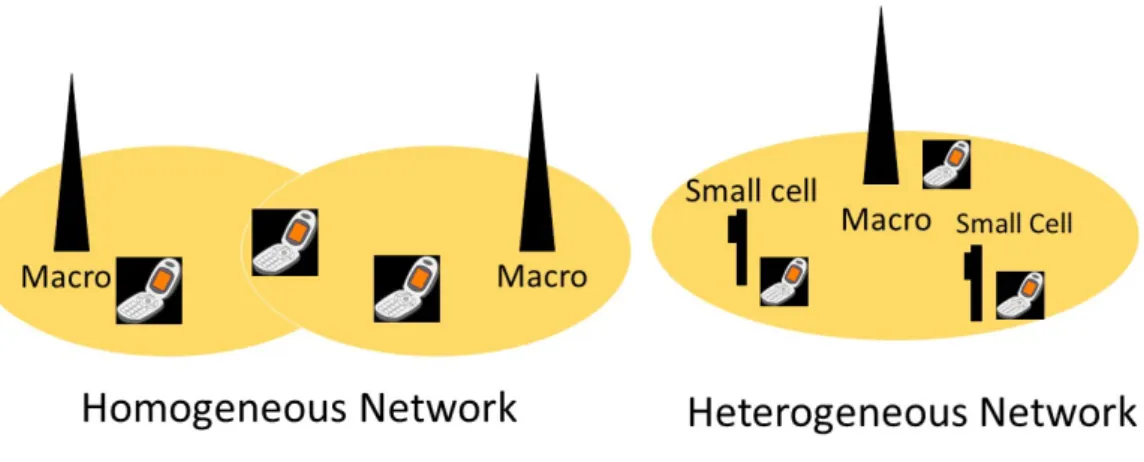
2 Illustration of a homogeneous and heterogeneous wireless network. . . 6
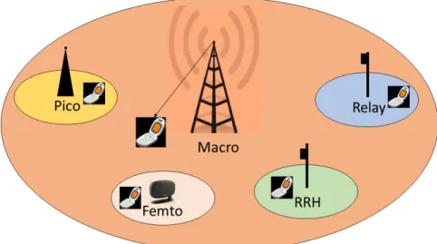
3 Heterogeneous network architecture where different cells are deployed together. . . 7
4 Illustration of femto cell signal transmission from the mobile operator network. . . 9
5 Interference scenario occuring in the heterogeneous network. . . 12
6 Demonstration of channel allocations used in frequency domain. . . . 13
7 Illustration of hard frequency reuse method. . . 14
8 Illustration of fractional frequency reuse method. . . 15
9 Illustration of soft frequency reuse. . . 15
10 Flow diagram of steps involved in interference management using ABS. 17
11 ABS pattern frequently used in frequency domain and time domain deployment. . . 18
12 Illustration of system model. . . 21
13 Demonstration of intertier interference between the MBS and FBS. . 22
14 Illustration of intertier interference management using ABS. . . 23
15 Average MU rates using different ABS and power control schemes. . . 31
16 Average FU rates using different ABS and power control schemes. . . 31
17 Heterogeneous network with multiple macro users in downlink. . . 33
18 Illustration of case 1, where the closest macro user to FBS is also farthest away from the MBS.. . . 36
19 Illustration of case 2, where the macro user is closest to both FBS and MBS.. . . 37
20 Illustration of contour plot to show that the macro user which is closest to both MBS and FBS will have minimum capacity compared to other macro users which are further away. . . 38
21 Illustration of a heterogeneous network where a MBS is surrounded with many FBS in downlink. . . 41
22 Illustration of intratier interference between FBSs. . . 42
23 Flow chart representation of round robin scheduler. . . 43
List of Tables
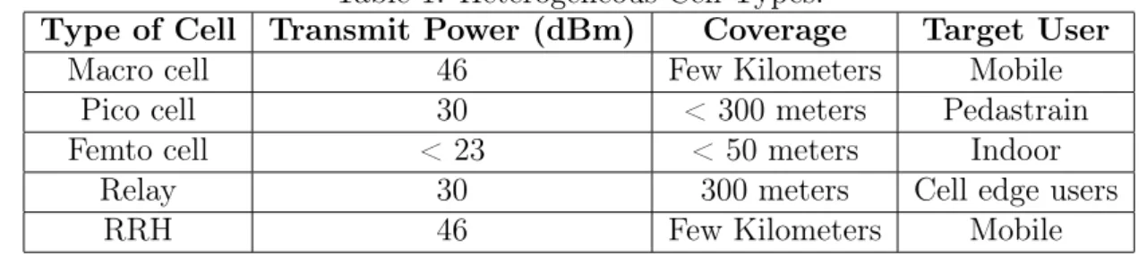
1 Heterogeneous Cell Types. . . 8
Symbols and abbreviations
Symbols
P0 MBS transmission power P FBS transmission power
Pmax Maximal transmission power of FBS γ Signal-to-interference-plus-noise ratio
G Channel power gain
n Pathloss exponent
A Fixed loss
d Distance
R0(P) Rate of macro user R1(P) Rate of femto user PN Thermal noise power
N Number of subframes
L Number of normal subframes
CM U Capacity of macro user CF U Capacity of femto user
CT Target capacity of macro user Popt Optimal value of power Lopt Optimal value of subframes Pd Critical power
ξ(P) Optimization function
˜
L(P) Optimum value of normal subframes
Lf Floored value of subframes Lc Ceiled value of subframes
Abbreviations
LTE Long term evolution
MIMO Multiple-input multiple-output CoMP Coordinated multipoint
3GPP Third generation partnership project RRH Remote radio head
MBS Macro base station FBS Femto base station CSG Closed subcriber group SON Self organising network
ICIC Intercell interference coordination
eICIC Enhanced intercell interference coordination HFR Hard frequency reuse
FFR Fractional frequency reuse SFR Soft frequency reuse
SINR Signal-to-interference-plus-noise ratio ABS Almost blank subframe
CRS Common reference signal PSS Primary synchronization signal SSS Secondary synchronization signal PBCH Physical broadcast channel SIB-1 System information block-1
PDCCH Physical downlink control channel CQI Channel quality indicator
1
Introduction
With the exponentially growing popularity of connected devices such as smartphones and wireless connected tablets, the wireless industry is confronted with a demand for huge data rates with ubiquitous wireless coverage. Smartphones generate heavy data traffic compared with basic featured mobile phones. The dominant part of data traffic generated nowadays are from indoor environments like office building, shopping malls etc. In order to satisfy the galloping demand for high data traffic in indoor locations and hotspots, traditional cellular deployments with homogeneous network plans are being replaced by a new network topology popularly known as the heterogeneous network. Heterogeneous networks consist of different kinds of smaller cells coexisting together with the main cell. Their main purpose is to provide for better indoor coverage. The heterogeneous network has many advantages over traditional networks in terms of deployment, coverage, efficiency and capital expenditure. The major technical challenge associated with heterogeneous network is the interference experienced between coexisting cells. This will degrade the performance of the system with the end result being poor user experience. To avoid such interference, various management techniques are proposed in time, frequency and power domain. One of the time domain technique is using almost blank subframe (ABS) where signal transmissions of small cells are muted at times to reduce the heavy interference on the users of other cells. Besides resource allocation schemes, power controlling of the small cells is also a feasible solution to reduce the interference. However, these interference management techniques eventually reduce throughput of the smaller cells. This necessitates the need to optimize the power and number of ABS transmissions in smaller cells such that a better tradeoff is maintained between interference experienced by the co-existing cells and throughtput of the smaller cells.
In this thesis, we consider a heterogeneous network consisting of a larger macro cell co-existing with the smaller femto cell. A macro user in the close proximity of a femto cell will experience severe interference from the femto cell. Due to this interference, the capacity of the macro user is reduced to a lower value. In order to improve the capacity of the macro user, and to provide better macro user experience, we use interference management schemes such as power control and ABS transmissions at the femto base station (FBS). However, power controlling and ABS transmissions at the FBS reduces the throughput of the femto user. Hence, a balance tradeoff to improve the capacity of both macro and femto user synchronously is essential. This is achieved by optimizing the power and number of ABS transmitted by the FBS.
1.1
Research Problem and Scope
The scope of this thesis is on interference management in heterogeneous networks using power control and ABS transmissions. We consider a heterogeneous network consisting of a central macro cell coexisting with a femto cell. The macro cell consists of a macro base station (MBS) servicing multiple macro users and a femto cell
servicing one femto user. However, using power control and ABS transmissions at the FBS reduces the throughput of the femto user. Thus, the goal is to optimize the power and number of ABS transmissions at the FBS, in order to maximize the throughput of femto user while keeping the interference of the macro users below a certain level.
1.2
Contributions of the Thesis
In previous work, optimal parameters of power and number of ABS transmissions at the FBS in downlink were obtained for a system with MBS serving only one macro user and FBS serving one femto user. We extend the analysis to determine optimal parameters when the macro cell serves multiple macro users. The macro users in the close vicinity of femto cell will experience severe interference from the femto cell, and thus, interference management must be performed for these macro users. However, the optimum value of power and number of ABS required for FBS transmission will be different for each macro user. So, the question is what value of power and number of ABS transmissions must be used such that the throughput of the femto user is maximized while keeping the interference of all the macro users below a certain level. This optimal value of power and number of ABS obtained will be used for controlling interference in the whole network.
• Specifically, we show that when multiple macro users are served by the macro cell, the optimal value of power and number of ABS obtained by performing interference management on the macro user closest to FBS is sufficient to guarantee maximum throughput to the femto user and tolerable interference for all other macro users.
• As a special case, when a set of macro users closest to the FBS are equidistant, we show that it is sufficient to perform interference management on the macro user that is furthest away from the MBS.
1.3
Thesis Structure
This section outlines briefly the basic organization of this thesis report. In Chapter 2, we review some of the proposed features of LTE-Advanced, specifically, features related to heterogeneous network deployment. One of the major technical challenges involved in heterogeneous network deployment is interference management between different cell types in the network area. Various interference management schemes are discussed in general with specific emphasis on time domain and power control schemes. In Chapter 3, we study interference management for a heterogeneous network with one macro cell and femto cell. We typically focus on the interference management between macro user and femto cell. We consider the problem to optimize the power and number of ABS transmission at the FBS, in order to maximize the capacity of the femto user while always ensuring a certain threshold capacity for the macro user. We discuss different interference management schemes depending on the optimal value of power and number of ABS obtained. We end the chapter with a discussion
on the numerical results. In Chapter 4, we extend the system setup in Chapter 3 to include multiple macro users. We consider a new problem to optimize the power and number of ABS transmission at the FBS in order to maximize the capacity of the femto user while always ensuring a certain threshold capacity for all macro users. We propose a criteria for selecting the particular macro user that has to undergo interference management when multiple macro users exist. The general selection criteria depends on the position of macro user with respect to the FBS. As a special case, we also propose the criteria when a set of macro users are equidistant from the FBS. In Chapter 5, we introduces a new system with multiple FBSs in downlink. In this chapter, we focus on interference management within femto cells and also between macro cell and femto cell. We discuss various interference management schemes used to avoid interference within the femto cells. We also propose a vector optimization problem in order to reduce the interference existing between the cells. Finally, in Chapter 6 we have the conclusion.
2
Chapter 2
2.1
Long Term Evolution (LTE)
In wireless communications, the demand for the higher data rate has grown ex-ponentially during the past few years [1]. To meet these expectations, extensive research is ongoing to develop new and advanced technologies that improve the capacity and coverage of the current wireless network. The mobile data traffic is increasing exceptionally in recent years due to the enormous usage of different mobile applications such as live video streaming, social network sites and online gaming [2]. Studies on wireless usage show that more than half of voice calls and majority of data traffic originate indoors, such as inside office buildings, shopping malls and residential areas [3]. Voice networks are tolerable to the low quality signal due to the low data rate requirement. Data networks, on the other hand, require higher signal quality. Figure. 1 shows the exponential increase in data traffic during the last five years [1].
Figure 1: Exponential increase in data traffic during the last five years [1] The cellular network has evolved from the first generation (1G) to fourth gen-eration (4G) to satisfy the demand for higher data traffic. Long Term Evolution (LTE) commonly marketed as 4G LTE, is a standard for wireless communications [4]. LTE offers higher throughput and lower latency compared with the 3G cellular networks [5]. It is mainly due to the large bandwidth usage in LTE. Bandwidth in general is a scarce resource and, thus, new ways have to be found to improve the network performance [6]. In order to enhance performance of the overall network, LTE-Advanced proposes the use of advanced technologies [7]. LTE-Advanced is a mobile communication standard and a major enhancement of the LTE standard.
Features proposed in LTE-Advanced release 10 are discussed below.
2.2
Features Of LTE-Advanced
To achieve higher network performance, LTE-Advanced include the following features:
• Carrier aggregation
• Multiple input multiple output (MIMO)
• Coordinated multipoint (CoMP)
• Heterogeneous network deployment
In this thesis, our focus is on heterogeneous network deployment. In the following subsections, we briefly summarize some of other main features of LTE-Advanced.
2.2.1 Carrier Aggregation
The operating bandwidth of the LTE system is 1 MHz to 20 MHz [8]. The carrier aggregation method is used to further extend the bandwidth which allows the concur-rent utilization of diffeconcur-rent frequency carriers [9]. This implies that several component carriers are aggregated and used for transmission. A maximum of five transmission components with the same or different carrier frequency can be aggregated at the same time. In this fashion the operating bandwidth of LTE is extended up to 100 MHz.
2.2.2 Multiple-input and Multiple-out
MIMO is a radio communications technology or RF technology in which multiple antennas are used at both the transmitter and receiver [4]. In conventional networks, one antenna is used at transmitter and another one is used at destination. This may create problems with multipath effect. The multiple antennas at transmitter and receiver in MIMO enable the transmission of more data through the same radio channel via multipath propagation. The antennas at each end of the communication circuit work synchronously to minimize the transmission errors and to optimize the data speed.
2.2.3 Coordinated Multipoint
CoMP enables dynamic coordination of transmission and reception over a variety of base stations using multiple antennas [4]. The main aim of this feature is to enhance overall system performance. It is used to ensure that optimum performance is achieved at cell edges where the peformance of mobile users may be degraded. Advantages of this feature include the better utilization of the network, enhanced reception performance for the user and to reduce the interference in the system.
The above mentioned advanced technologies are approaching towards theoretical limits in terms of spectral efficiency [10]. Moreover, the availability of usable spec-trum is limited. Thus, significant enhancement is not possible especially in case of attenuation, where the signal quality will be poor. One of the possible way to further improve network performance is by using enhanced network topologies. In order to enhance network performance, a new feature called the heterogeneous network has been introduced in LTE Advanced. Before describing the heterogeneous network in detail, we will review the traditional homogeneous network and its draw backs in the following section.
2.3
Homogeneous Cellular Network
The traditional wireless cellular network called the homogeneous network is shown in Fig. 2. The main element of the homogeneous network is the macro cell which consists of a MBS serving many macro users. All the base stations involved in the network possess equal transmission power, antenna patterns, the receiver noise floor and similar backhaul (link that connects core network to the subnetworks) connectivity to the data network [11].
Figure 2: Illustration of a homogeneous and heterogeneous wireless network.
2.3.1 Macro cell
The macro cell consist of a conventional cell tower installed in for proving wide area coverage for a few hundred kilometers. A cell radius below 500 meters is typically referred as micro cells. This increases the cell capacity and coverage. The MBS typically transmits with a power of46 dBm. To provide wide area coverage, several
macro cells are installed. The installation and maintenance cost of the macro cells are comparatively expensive. Poor indoor coverage and inability to focus on hotspots reduces the performance of the network. Moreover, site acquisition in urban areas can be a challenging task. These drawbacks demand a flexible model while ensuring better user experience. This is where heterogeneous networks will play a crucial role.
2.4
Heterogeneous Network
A heterogeneous network is a mixture of different kinds of cells that co-exist together. The cell types are macro cells, pico cells, femto cells, relays and remote radio head (RRH). These cells co-exist in the same area and share the same spectrum. The small cells in the network help in offloading data traffic from the macro cell and, thus, improve the indoor coverage. The heterogeneous network has many advantages over the traditional homogeneous cellular network. The network is deployed in a flexible manner due to the compact size of the elements involved in the design and, thus, provide better performance to the cell edge users [12]. Less upfront planning is required for the deployment of the network. Therefore, the operational and capital expenditures of the network will be comparatively less [13]. It also requires less energy consumption compared with the homogeneous networks [11]. Figure. 3 shows the network architecture of the heterogeneous network where all the network elements are deployed under one roof. The operating parameters of different cells in the
Figure 3: Heterogeneous network architecture where different cells are deployed together.
heterogeneous network are given in the Table 1. We now, briefly summarize the different cell types.
Table 1: Heterogeneous Cell Types.
Type of Cell Transmit Power (dBm) Coverage Target User
Macro cell 46 Few Kilometers Mobile
Pico cell 30 < 300 meters Pedastrain
Femto cell < 23 < 50 meters Indoor
Relay 30 300 meters Cell edge users
RRH 46 Few Kilometers Mobile
2.4.1 Pico cell
Pico cells are low power cells that co-exist with the macro cell for better coverage [14]. They support up to 100 users with a cell radius of 300 meters. Pico cells are installed in areas where the macro cell penetration is not sufficient. They transmit with a power of 30 dBm to its end users. They are usually installed and maintained directly by the network operator rather than individual customers.
2.4.2 Relays
Relay are operator deployed access points, that enable signal transmission between MBS and user equipment and vice-versa [4]. Relays are used to enhance both coverage and capacity, especially at the cell edges and tunnels using high gain antennas. LTE relays are installed in many convenient areas like on street lamps and walls, due to their small size. No separate backhaul is required for the deployment of relays [15].
2.4.3 Remote Radio Head (RRH)
RRH are high power, compact size and low weight units used to expand the reach of wireless voice and data network [16]. It acts as an extension of the macro cells antenna connected through fibre optic cables. It eliminates the power loss in the antenna cable and, thus, reduces the power consumption. It enhances flexibility for network deployments for operators that face site acquisition challenges.
2.4.4 Femto cells
Femto cells are small cellular telecommunication base stations installed in residential or business enviroment. The femto base stations are also called HeNBs or home base station. About 50% of voice calls and 70% of data traffic originate indoors according to recent studies [1, 3]. To meet the higher demands and for better indoor coverage femto cells are deployed widely in the vicinity of the cell area. FBS are low power, low cost and short range, that help in offloading the heavy data traffic handled by the MBS. Comparatively, low capital and operational expenditure is required for the deployment of femto cells. They are operated with a transmit power of 23 dBm with a range of less than 50 meters. The battery consumption of user equipment is significantly reduced when it is connected to a femto cell in comparison with a
macro cell, due to the fact that the femto users need less transmit power. Femto cells are installed and maintained by customers, primarily for their own benefit, and they determine the operating frequency and power level rather than being directed from a centrally determined master plan. Hence, a complete frequency replanning is not required when a femto cell is added or removed from the network. The access policies of femto cells are discussed below [17, 18]:
• Open-access policy : Under the open-access policy of the femto cell, the user is allowed to associate with any adjacent base station. The general trend is to associate with the base station that provide the strongest signals to the users, which may eventually lead to overloading of that particular cell [17, 19].
• Closed-access policy : Unlike the open-access policy, closed-access policy allows only pre-registered users to share the femto cell resource. These pre-registered users form a group know as the closed subscriber group (CSG). The interference will be high under the closed access policy, since the signal strength at the user from the serving base station could be much lower than that from an interfering base station [20]. In spite of the interference problem, this policy is used widely in residential purpose due to privacy issues [21].
• Hybrid-access policy : Hybrid-access policy is a combination of both open access and closed access policies where a part of resources are open to all users, and the rest of the resources are under the CSG mode.
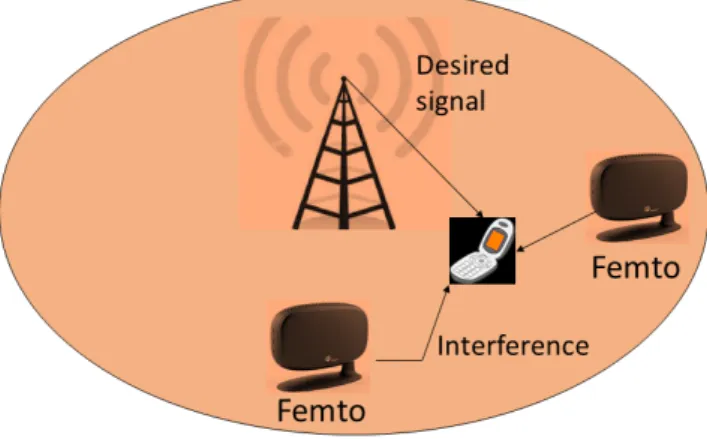
Figure 4: Illustration of femto cell signal transmission from the mobile operator network.
Figure. 4 shows the routing of signals from the mobile operator network to the individual femto users. The femto cell is connected to the service provider’s network
using a broadband router. All the users under the closed access policy of femto cell are served properly.
2.5
Technical challenges in heterogeneous network
The major technical challenges in deploying heterogeneous networks are as follows:
• Self-organising networks (SON)
• Backhauling
• Mobility management and handover
• Intercell and intracell interference
2.5.1 Self-Organising Networks
SON is used to configure, organize and optimize the performance when error or problem occurs in the network. Less human intervention is required for building and operating a SON. Hence, the chances of human errors are minimized and, thus, the operational cost is reduced. In heterogeneous network, self-organising operates in three main areas [22]:
• Self-configuration: It enables new cell sites to be configured automatically with less manual interference using a plug and play approach. Thus, the total operational cost is reduced while ensuring that the cell integrates correctly into the overall network.
• Self-healing: The failure detection system of the network may have faults from time to time. The system has to detect and repair faults. It ensures the proper operation of the overall cellular network even when failure occurs.
• Self-optimization: Optimization is required to ensure that the installed cell is proficient to perform in its best level of efficiency. The network monitors the performance, and modifies the network parameters accordingly so that the system requirements are met.
In case of the heterogeneous networks, where different kinds of cells co-exist, the implementation of SON is complicated and iterative. Cells like femto cells are operated and individually controlled by customers rather than a centralized operator. Hence, controlling these types of cells is a difficult task [14]. Above all, sudden change in data traffic adds complication to system management.
2.5.2 Backhauling
Backhaul is the main link that connects the core network to the small subnetworks. Due to the complex topology of different co-existing cells, good planning is required to have cost effective backhauling techniques [22]. Even though femto cells have low
backhauling cost, the cell operation depends on individual customers, hence, the quality of service (QoS) will be difficult to manage. On the other hand, pico cells requires wired backhauling which is expensive. Relays are effective where wireline backhaul is not available. To summarize, the heterogeneous network is a combination of wireless and wired backhaul technologies which poses real challenges to the network.
2.5.3 Mobility Management and Handover
Supporting seamless handover across the heterogeneous access network requires sev-eral functionalities to be taken into account, such as QoS, security, power management, service continuity etc [14]. Roaming across heterogeneous network is challenging as each cell may have different mobility and handover requirements. Due to different kinds of cells and backhaul links, handover within the network will be complex. In addition, the probability of handover failure increases the probability of user outage [22].
2.6
Intertier and Intratier Interference
The interference experienced in the heterogeneous network is high in comparison with the traditional cellular network. In a heterogeneous network, where small cells are deployed within a macro cell, the access control of small cells is different which leads to different interference scenarios [20, 17]. For instance, a femto cell which operates mostly in the CSG mode, the users outside the closed group are not allowed access even if they experience a strong signal. This leads to heavy interference phenomena. On the other hand, in an open access mode, all users of the network are allowed to access the femto cell. However, open access policy is not a wise trend to follow as then the users always tend to connect to the macro cell which possess the highest transmit power, and hence there will be heavy congestion over the macro cell. Continous sensing and balancing of traffic load is required to avoid interference. The self organising capabilities of the network should be excellent for better network performance. Interference may also occur due to unplanned deployment. The network consists of cells that are operator deployed and customer deployed. The location and traffic of the customer deployed cells vary as they are not controlled by a centralized authority. Interference in heterogeneous network are categorized into two types [15]:
– Intertier (Interference between different cell types) – Intratier (Interference among same cell types)
• Intertier interference: Intertier interference is between different cell types within a network, such as between macro and femto, macro and pico etc. A macro user in close proximity to a femto cell will experience heavy interference from the femto cell signal especially if the femto cell is in CSG mode. To avoid the interference, different intercell interference coordination techniques (ICIC) are used which we will discuss in detail later in this chapter.
Figure 5: Interference scenario occuring in the heterogeneous network.
• Intratier interference : Intratier interference is an important problem in downlink where users experience interference from same cell types, such as between femto cells or pico cells etc. Femto cells work mainly in two network enviroments, namely, enterprising network (for e.g.,shopping malls, office buildings etc) and residential network. These cells experience strong intratier interference in the enterprising network than the residential network because of heavy traffic and wide coverage. Thus, proper coordination techniques are required to avoid this type of interference.
In this thesis, we focus on a heterogeneous model with mixed macro and femto cells as shown in Fig. 5.
2.7
Interference Management Techniques
eICIC (enhanced ICIC) technique has become an essential requirement in hetero-geneous network deployment, which involves resource coordination, transmission and power coordination among interfering base stations. Different eICIC techniques proposed and introduced in 3GPP release 10 are discussed in detail [23].
• Frequency domain techniques
• Time domain techniques
2.7.1 Frequency Domain Techniques
Carrier aggregation and frequency allocation
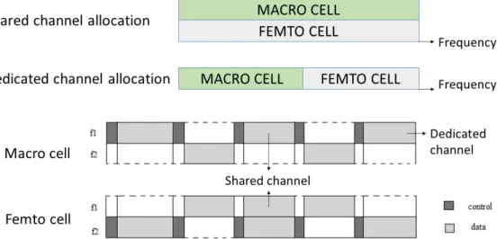
Carrier aggregation is one of the main frequency domain interference management method used in LTE Advanced (discussed in Section 1.1.1 of this chapter). In addition to resource allocation, it performs fast switching between carriers without spending too much time for handovers. Frequency allocation is in the form of shared channel or dedicated channel to the cells [24]. In the shared channel, all the cells in the network uses the same frequency band [25]. So the amount of interference will be high, whereas on dedicated channels the whole channel is exclusively dedicated to a single kind of cell, so the interference will be minimized and more number of small cells of the same kind can be deployed [26]. However, the spectrum available
Figure 6: Demonstration of channel allocations used in frequency domain. to operators is often limited and expensive [27]. Hence, the operators focus mainly on shared channels. In order to utilize the maximum of both channel allocation schemes, a partially shared channel allocation that balances the tradeoff between the two allocation schemes is used. In the partially shared channel, a few channels are dedicated to the macro cells and rest are shared between macro and other smaller cells of the network [28]. The MBS allocate shared channels to the macro users that are far away from the small cells and allocate the dedicated channel to the macro users that are close to the small cell. Figure. 6 shows the different channel allocation schemes used in the frequency domain.
Frequency reuse methods
Frequency reuse methods used to reduce the intertier interference between the cells can be categorized into the following types [29]:
• Hard frequency reuse (HFR): In HFR, the neighboring base stations operate on different frequency bands, as shown in Fig. 7, which helps to reduce the intertier interference. The number of different frequency subcarrier sets required will depend on the number of neigboring cells. The subcarriers are assigned to each cell in such a fashion that the neighboring cells uses a different frequency set. This scheme significantly minimizes the interference at the cell edge. However, on the other hand it reduces the spectrum efficiency drastically as the full resource blocks are not utilized.
Figure 7: Illustration of hard frequency reuse method.
• Fractional frequency reuse (FFR): In FFR, the macro cell area is divided into two areas: the first area is the cell center area and the second area is cell edge area. The cell center areas of all the cells use the same frequency band and the cell edge areas of neighboring cells use different frequency band as used in hard frequency reuse method. This is shown in Fig. 8. Thus, the interference between cells is minimized with an improvement in spectrum efficiency [30].
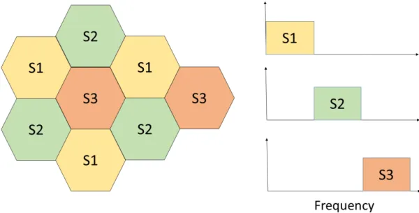
• Soft frequency reuse (SFR): SFR is considered as the most effective frequency reuse technique. Here a primary subband of high transmission power is allocated to the cell edge users. The cell edge users of the neighboring cells must not use the same set of frequency resources. This is shown in Fig. 9. However, the spectrum allocated to the cell edge may be also used by the cell center users if
Figure 8: Illustration of fractional frequency reuse method.
it is not used by the former one. This method helps to improve the SINR of cell edge users without degrading the performance of the cell centered users [31]. The spectral efficiency of the system is high since all the frequency bands are used within a cell.
2.7.2 Time Domain Techniques
Each LTE frame of duration 10 milliseconds (ms) consists of both data and control parts. Each frame is further sub-divided into subframes of 1 ms each. The time domain eICIC techniques are implemented to protect the cell layer that suffer from heavy interference. This is achieved by reducing the transmission activity of certain base stations in certain subframes. This concept relies on the accurate timing and phase synchronization between the base stations within a certain coverage area. In this approach, the base station that causes severe interference to others are periodically muted. To prevent radio link failure during transmission, the signals should not be completely muted. No data and control signals are transmitted during this time but it requires some basic reference signals and, hence, it is called Almost Blank Subframes (ABS). The basic reference signals needed to be transmitted are given below [32]:
• Common reference signal(CRS)
• Primary and secondary synchronization signals (PSS and SSS)
• Physical broadcast channel (PBCH)
• System information block-1 (SIB-1) and paging with their associated physical downlink control channel (PDCCH)
In a heterogeneous network with mixed macro and pico cells, if the users in range extension area of the pico cell experience severe interference from the high power node then the MBS is muted in order to provide better signal strength for the pico users. The pico users operates in two regions. The first region consists of users in range extension area which suffer from heavy interference and the second region consists of users that are close to the pico nodes. Generally, the users in range extension area which suffer high interference are scheduled during ABS and those which are close to the low power nodes are scheduled during nonABS. Whereas in a heterogeneous network where macro and femto co-exist, the femto cell is muted so as to serve the macro user in better manner. Hence, the macro users in the close vicinity of the femto cell are scheduled when the femto cell is transmitting ABS [14].
Almost Blank Subframes
In this section, the interference management in the macro-femto scenario using ABS is discussed in detail [33] . When a macro user served by the MBS is in the close vicinity of a femto cell which is working in the closed access mode, it may experience severe interference resulting in degradation of the signal-to-interference-plus-noise ratio (SINR). According to the 3GPP standards, the typical values of the target SINR for downlink control channels are −6 dB or −4dB [34]. When the SINR falls below this value, the macro user will not be able to receive the control and data channels properly. To avoid such situation, we mute the transmission of the femto
cell in certain subframes and provide interference free transmission for the macro user. The target capacity of the macro user is the criteria used for muting the FBS.
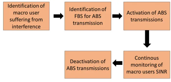
For interference management using ABS, the macro user that suffers from the heavy interference of the femto cell is to be determined. Subsequently, the MBS should indicate to the FBS to start the ABS transmission. Continous monitoring of the SINR of the victim macro user is required to ensure whether the SINR value is above or below the required level. As soon as the macro user’s capacity is above the target level, the MBS reports to the FBS to stop the ABS transmissions. Precise coordination between macro cell and its user and macro cell and the femto cell is required for this procedure to be effective. The various steps involved in interference management using ABS is shown in Fig. 10.
Figure 10: Flow diagram of steps involved in interference management using ABS.
• Identification of macro user suffering from interference : The identification criterion is based on the SINR of the macro user. If the SINR, is below a set target level then the macro user experiences interference from a near by femto cell. The ABS transmissions are then activated and is kept on going until the required SINR is achieved. The SINR values of all macro users are obtained from the channel quality indicator (CQI) report [35]. Larger the value of CQI, superior is the quality of the signals. The CQI in LTE is a 4-bit integer with 16 possible values which varies depending on the SINR of the macro user. CQI will be either periodic or aperiodic. The aperiodic CQI is reported to the MBS if and only if requested while a periodic CQI is reported consistently to the MBS. The reported values are used by the MBS to schedule the ABS transmission.
• Identification of femto cell for ABS transmission : The identification of the femto cell responsible for causing interference to the macro user is indispensible.
The victim macro user reports its serving MBS with the necessary information regarding the neighboring femto cell’s received signal. The information set consist of the values of interference level that each femto cell imposes on the macro user in an increasing order. From the received information set, the MBS detect the femto cell that is offering maximum interference to its user and consequently notify the femto cell to intiate the ABS transmission.
Figure 11: ABS pattern frequently used in frequency domain and time domain deployment.
• Activation of ABS transmission : Once the femto cell causing interference is identified, the ABS mode is activated. Coordination between the macro and femto cell is needed to activate the ABS transmission process. The MBS must inform the femto cell about the specific ABS pattern to be followed during the transmission. The pattern is selected based on many parameters such as amount of interference, the number of users in the interference area and the signal quality requirement for the femto users. Blanking of the femto cell will eventually degrade the throughput offered to its users. Scheduling algorithms that define the ABS patterns precisely are selected for maintaining a balance between interference and performance. The specific subframes where ABS transmission should be carried out will be programmed in the pattern. The frequently used ABS patterns in frequency and time domain deployments are shown in Fig. 11 [36].
• Continous monitoring of macro users SINR : CQI of all the victim macro users should be monitored continously in each subframe as soon as the ABS transmis-sion is activated. The SINR of the macro users for the subframe preceding the
ABS will be low because of the interference. The ABS transmission in certain subframe will improve the signal quality of the victim macro user, as a result, the SINR will improve and the corresponding interference imposed will be reduced. When the macro user is no longer affected by the severe interference of the FBS, it is rescheduled with nonABS subframes.
• Deactivation of ABS transmissions : Timely deactivation of ABS transmissions is essential for upholding the performance of the femto users. As soon as the SINR of the victim macro user goes above threshold level during normal subframe transmission, the MBS notifies to FBS to deactivate ABS transmission mode.
2.7.3 Power Control Techniques
Power control is a significant eICIC technique, where the transmit powers of the small cells are controlled for limiting the interference imposed by it on the other users in the cell area. The MBS transmits constantly with a fixed power level while the power of small cells depends on the interference conditions. Power control techniques are widely adopted as it is used to scale down both intertier and intratier interference between cells. The high transmit power for the femto cells provide wider coverage area and better signal quality to its users, concurrently, it may cause heavy interference to the surrounding macro users [37]. Thus, an appropriate femto transmit power is required to reduce interference to the macro users while ensuring the performance of the femto user. Different algorithms are used to regulate the transmit power of FBS in downlink [38, 39]. We briefly summarize some of these methods:
• Fixed power level : In this approach, all femto cells within the cell area operate with a fixed power level. The power level is fixed by the network coordinators based on the density of the femto cells within a cell area. The fixed power level should be consistently lower than the maximum power available in the femto cell. This method is very useful in separate channel operation scenarios where femto and macro cells are scheduled in different carrier frequencies.
• Femto-QoS power control : The goal of this scheme is to ensure that the femto users QoS is maintained. In this method, the femto cells transmit with sufficient power to support its user’s QoS. No guarantee is made on the macro users performance and the interference level. The QoS constraint can be indicated as in the form of target SINR values for the femto users. Based on the target SINR, the transmit power is selected and fixed. The femto cell adjusts their transmit power to ensure the target SINR to the weakest femto user. In simple words, the femto cells closer to the MBS should transmit with higher power compared with those which are further away from it. However the transmit power of the femto cells should not exceed the maximum power constraint.
• Macro-QoS power control : Unlike femto-QoS power control, macro-QoS power control gives prominence to the performance of the macro user and its interfer-ence management. The idea is to limit the interferinterfer-ence imposed by the femto
cells on the near by macro users. Here the power of the femto cell is regulated to offer limited interference to the surrounding macro users. First and foremost the amount of interference that each femto cell imposes on the macro users is calculated. The femto cell which causes strong interfering signals to the macro users is the determined from the obtained interference value. Finally, the MBS notifies the femto cell to adjust its transmit power to match the macro user’s target SINR.
2.8
Summary
In this chapter, we give an overview of the 4G LTE cellular network. The focus is on LTE technologies and their proposed features for the better enhancement of the cellular network. Carrier aggregation, MIMO, CoMP and heterogeneous network deployment are the main features discussed in this chapter. Among these, the heterogeneous network deployment is identified as one of the most prominent feature which improves the performance of the network by changing the traditional cellular network topology. Different kinds of cells involved in the heterogeneous network deployment are studied carefully and its merits and demerits are figured out. On top of several benefits, the heterogeneous network deployment inlcudes a few drawbacks which will degrade the quality of the signal served to the users. The self organizing incapabilities, backhauling problems, difficulty in handovering signals to the users outside the access area and heavy interference caused by the neigboring cells are some of the drawbacks. Interference between the different kinds of cells of the heterogeneous network is the primary reason for the poor system performance. The two types of interference in heterogeneous network are intertier and intratier interference. To avoid the attenuation caused due to interference and to enhance the network performance, many interference management techniques are developed. The commonly used interference management techniques described here in detail are the frequency domain, time domain and power control techniques.
Chapter 3
3
Interference Management In Heterogeneous
Net-work
In this chapter, we summarize the work of [40] and use these results in the following chapters. The focus is on downlink signal transmission through out the thesis. We introduce a system model that consists of macro and femto cells co-existing together in Section 3.1. The main technical challenge in such a scenario is intertier interference existing between the MBS and FBS. This intertier interference will degrade the performance experienced by the users within the cell area. To avoid such interferences and to provide better user experiences, various interference management techniques are introduced in Section 3.3. Specifically, we consider time domain (using ABS) and power control interference management techniques that are used to improve the overall performance of the network. In order to maintain the capacity of both macro and femto users, we optimize the amount of power and ABS used in downlink. The optimization problem proposed in [40] is discussed in Section 3.6 of this chapter. We categorize the various interference management schemes depending upon the optimal value of power and ABS used in FBS . The simulation results of various interference management schemes is discussed in the final section of this chapter.
3.1
System Model for Heterogeneous Network
The system model consists of a central MBS surrounded by several FBSs. The interference between individual FBSs also known as intratier interference is avoided by allocating non-overlapping bandwidth to each FBS. Hence, it is sufficient to consider any one particular FBS and study the interference between the MBS and chosen FBS. Such a systemic setup is shown in Fig. 12. In this scenario, we assume only one femto user and one macro user in downlink.
3.2
Intertier Interference
In this section, we address intertier interference between MBS and FBS which is considered to be one of the main technical challenges associated with heterogeneous networks. Based on the system model, there are two kinds of intertier interferences happening in downlink. The first type is the FBS causing interference to the macro user, and the second type is the MBS causing interference to the femto user. Among these, interference caused by FBS to macro user will be more severe. This is because of the fact that the FBS are normally installed in areas where the MBS-to-macro-user equipment link is poor, such as macro cell edges and indoor locations.
Figure 13: Demonstration of intertier interference between the MBS and FBS. In a heterogeneous network, FBS mostly works in CSG mode, i.e., only pre-registered users under the closed access policy are associated with them. A macro user in the close proximity of a FBS as shown in Fig. 13 will receive strong signals from the nearest FBS than its own MBS. However, due to the closed group policy, macro user cannot be handed over to the FBS. Hence, the macro user will experience severe interference which will eventually reduce its capacity drastically. To decrease the FBS-to-macro-user-interference, many techniques have been proposed by researchers in the
recent years. These include interference cancellation or suppression techniques [13]. Successive interference cancellation by eliminating the strong interfering neighbor from the received signal is not that promising since it will alter the content of the signal [41]. Instead of suppressing the mutual interference, an interference avoidance approach is more likely to work well in heterogeneous network. To avoid interference and to make a reliable network, eICIC techniques are used.
3.3
Enhanced Intercell Interference Coordination Techniques
(eICIC)
eICIC is critical in heterogeneous network deployment. It involves resource coordi-nation, transmission and power coordination among the interfering base stations. Among the different interference management schemes, we focus on time domain and power control techniques. The behaviour of eICIC techniques depends on the nature and tuning of the cell. Nevertheless, there is always a trade-off between the performance of both victim macro user and aggressing FBS.
3.3.1 Time Domain Interference Management using ABS
In this approach, the signal transmission from the FBS is muted periodically in certain subframes [33]. Thus, the macro user in close proximity to the FBS will experience no interference. During ABS, no data and control signals are transmitted and thus, the SINR experienced by the macro user will improve as soon in Fig. 14. The muting is not complete as some reference signals are still transmitted to avoid radio link failure. Hence, the name ABS.
In order to apply muting, there should be strict time synchronization between the MBS and FBSs, concurrently both network layers should be aware of the muting pattern [42]. Muting generally degrades the performance of the FBS. The general rule is that macro user in the cell edge area or those which are suffering high levels of interference from the FBS should be served during ABS and the users that are not affected heavily by the intertier interference should be served during normal subframes. By this method, the high level of interference suffered by the macro user can be reduced and, hence, its received SINR will be improved.
3.3.2 Interference Management by Power Control
Power control is also a viable solution to reduce interference within a network. By reducing the radiated power at the FBS, the interference imposed by it on the neighboring macro user will be reduced and, hence, the capacity of macro user will be significantly improved. This, however, has the downside of reduced femto user capacity since the radiated power is lowered. Thus, there should be a properly coordinated power control scheme that will balance the throughput of both macro and femto users.
In some power control techniques, the FBS automatically adjusts the power based on the path loss measurement or interference, by properly listening to and monitoring the network whereas in some other methods, the transmit power of the FBS is statistically set on an appropriate value, called as static HeNB power setting [42]. During power control, all channel state information such as channel conditions and resource allocation should be known a priori. By that way, the FBS can sense the channel information and act accordingly to provide better system performance.
3.4
Rate Analysis without Intertier Interference Management
Throughout the analysis, the macro layer is subscripted with 0, and the femto layer is subscripted with 1. We assume that the MBS transmits with constant power P0
while the FBS transmits with power P where 0< P ≤ Pmax, Pmax is the maximum
power transmitted by the FBS. The SINR for both macro and femto user is given by
MU-SINR γ0 = P0G00 PN +P G10 (1) FU-SINR γ1 = P G11 PN +P0G01 (2) where PN denotes the thermal noise power and Gis the channel power gain. The
respective channel power gains between base stations and mobile users are denoted byG00,G01,G10 and G11. The channel power gain is typically defined as
G=Ad−n (3)
where A is the fixed loss or wall penetration loss,n is the pathloss exponent and d is the distance between the corresponding base station and mobile user.
First, we define the following:
γ =P0G00/PN, h=G10/PN, b =
G11 PN +P0G01
The rate equations for both macro and femto user in each subframe are given by
R0(P) = log(1 +γ0) = log 1 + γ 1 +hP = log 1 + P0G00 PN 1 + G10P PN (4)
R1(P) = log(1 +γ1) = log(1 +bP) = log
1 + G11P
PN +P0G01
(5) The value of channel power gain G10 increases as the macro user is in the close
proximity of the FBS, i.e.,under severe intertier interference condition. From (4), it can be seen that the rate of the macro user is inversely related to the channel power gain powerG10 and the power P of the interfering FBS. Hence, it implies that the
intertier interference causes reduction in rate of the macro user.
At the time of high data traffic, FBSs are deployed to offload the MBS by transmitting in all subframes with maximum power as seen in (5). However, if the macro user is close to the FBS, then the interference imposed on it will be comparatively high. Similary, if the FBS is transmitting with maximum power in all subframes then the rate of the macro user will be reduced which can be seen from (4). This necessitates intertier interference management to provide better data rates for the mobile users of MBS and FBS.
3.5
Rate Analysis using eICIC Techniques
We consider an LTE frame which consists of N subframes. The subframes can be of two types where the first type consist of normal subframes and second type are the ABS. The total number of normal subframes is denoted by L and (N −L) is the number of ABS. For better power management, the FBS transmits with different levels of power during normal and ABS subframes. It transmits withP=0 during ABS transmission, and during normal subframes it transmits with a power P which ranges from0< P ≤ Pmax, wherePmax is the maximum power. The MBS transmits
always with a constant powerP0 = 46dBm. The rate equations for macro and femto
user for these subframes are given by
R0(P) = log(1 +γ0) = log 1 + γ 1 +hP R0(0) = log(1 +γ) R1(P) = log(1 +γ1) = log(1 +bP) R1(0) = log(1) = 0 (6)
frame of length N as
CM U = (N −L)R0(0) +LR0(P) (7) CF U = (N −L)R1(0) +LR1(P) (8)
The capacity of the macro and femto user depend on the variables N and L. In (7) and (8), when we set L=N, the corresponding capacity of the mobile users are given by
CM U =N R0(P), CF U =N R1(P)
When L=N, there will be no interference management and the femto user will transmit in all subframes and, hence, the capacity of the macro user will be poor and the capacity of femto user will be high. Similarly, when L=0 the capacity of the femto user CF U=0. Thus, we need to optimize the values of P and Lin order to
maximize the rates of macro and femto users.
3.6
Problem Motivation
The macro user in the close proximity of the FBS will experience severe interference due to the CSG mode of operation. To avoid the interference, eICIC techniques using ABS or power controlling of FBS are used. In the time domain ABS method, MBS transmits in all subframes and FBS will be muted by sending ABS whenever necessary. However, unplanned muting and controlling of power of FBS will result in drastic reduction in the capacity of the femto user. In order to maximize the capacity of the femto user while keeping the capacity of the macro user above the target level (where CT is the target capacity of macro user), we have to optimize
the power of the FBS and the number of ABS to be used in downlink. We consider different cases, whereLis treated as integer value, as non integer value, taking power control alone into consideration, and a case where no interference management is done. In all these cases, the aim is to maximise the capacity of femto user while keeping the capacity of the macro user above the threshold level.
These optimal values are obtained by solving the following optimization problem: (P1:) Maximize
P,L CF U(P, L)
s.t CM U(P, L)>CT
0< P ≤Pmax,0≤L≤N, L∈Z
(9)
Depending upon the values of the optimal parametersP andL, we can categorize the interference management schemes as follows:
– Without interference managament – Single level power control
– Joint power and ABS control using noninteger L
3.6.1 Without Interference Management (WIM)
From the rate equations of macro and femto user given by (6), it can be seen that
R0(0) > R0(P) and R1(0)< R1(P)
Thus, using (7) and (8), the capacity of the macro user, CM U is a decreasing function
of P and L, where as the capacity of the femto user, CF U is an increasing function
in these parameters. To maximizeCF U, the value of P andL should be chosen as
large as possible. Thus, the optimal solution lies either on the boundary defined by
CM U = CT, where CT is the set target capacity, or whenP =Pmax and L=N. But
for this value of optimal solution, it implies there is no ABS transmission taking place, and the interference is within tolerable limits. Therefore no interference management is performed. The capacity of the users with parameters (Popt, Lopt)=(Pmax, N) is
given by
CM U =N R0(Pmax), CF U =N R1(Pmax) (10)
For optimal values other thanPopt = Pmax and Lopt = N, it implies that the macro
user will experience interference such that without interference management its capacity will be less thanCT.
3.6.2 Single Level Power Control (SLPC)
Even if the problem considers joint optimization using ABS and power control in downlink, it is not necessary that the optimal solution should follow a joint scheme. By relaxing the integer requirement of L, either power control or ABS is optimal. In SLPC, we haveLopt=N. For Lopt=N, we define the critical power as
Pd= 1 h γ 2CT/N −1−1 (11)
where for P < Pd, we have CM U < CT. Thus, (Popt,Lopt)=(Pd, N), and the
corre-sponding macro and femto user capacities are
CM U =N R0(Pd) (12)
CF U =N R1(Pd) (13)
3.6.3 Joint Power and ABS Control using Noninteger L
We now try to analyse the optimal solutions whenPopt and Lopt do not achieve their
maximum value. We allow L to take noninteger values. The intervals of P and
L provide insight on the possible values of the optimal solutions. If the optimum solution lies on the boundary ofCM U =CT, then the capacity equation for macro
user is given by
CM U = (N −L)R0(0) +LR0(P) =CT (14)
From (14), we define the optimum value of Las
˜
L(P) = N R0(0)−CT
R0(0)−R0(P)
(15)
Therefore by relaxing the integer requirement for L, (P1 :) can be converted to problem (P2 :) as
(P2:) Maximize ξ(P)
s.t Pd≤P ≤Pmax
(16)
where Pd is the critical power given by (14) and ξ(P) =CF U(P,L˜(P)) =
N R0(0)−CT R0(0)−R0(P)
!
R1(P) (17)
It is shown in [40] that the optimal solution is obtained with either P = Pd or P =Pmax. Thus, the optimal solution for noninteger Lis given by the equation
maximize
Pd≤P≤Pmax
ξ(P) = max[N R1(Pd), ξ(Pmax)] (18)
If N R1(Pd)is the maximum in (18) then the corresponding capacity of the users are CM U =N R0(Pd), CF U =N R1(Pd)
Similarly, ifξ(Pmax)is of the maximum value in (18) then the corresponding capacity
of the users are given by
CM U = (N −L(Pmax))R0(0) +L(Pmax)R0(Pmax) (19) CF U =
N R0(0)−CT R0(0)−R0(Pmax)
R1(Pmax) (20)
3.6.4 Joint Power and ABS Control Optimization with Integer L
From the nonintegerL case, it can be concluded that optimal solution is obtained with parameters either (Pd, N) or (Pmax,L˜(Pmax)). In this section, we require Lopt
to be always an integer. One possible way is to quantize L˜(Pmax) which leads to a
suboptimal solution. Depending on the type of quantization two suboptimal solutions are obtained which is the topic of the following subsections.
Suboptimal Solution 1 (SUB1)
We round down the value of L˜(Pmax)to an integer value as Lf = j ˜ L(Pmax) k (21) where b·c denotes the floor operation. The suboptimal solution for parameters P
and L are given by
(Psopt1, Lsopt1) = arg max[CF U(Pd, N), CF U(Pmax, Lf)] (22)
Since the value of Lis rounded down, the capacity of the macro user increases which provides a feasible solution while the capacity of the femto user decreases and, thus, optimality cannot be guaranteed.
Suboptimal Solution 2 (SUB2)
Another suboptimal solution can be obtained by rounding up the nonintegerL˜(Pmax)
to an integer value as Lc = l ˜ L(Pmax) m (23) where d·edenotes the ceil operator. The suboptimal parameters P and Ldenoted as
(Psopt2, Lsopt2) are given by
(Psopt2, Lsopt2) = arg max[CF U(Pd, N), CF U(Pc, Lc)] (24)
where Pc≤Pmax and Pc can be found from the following equation
CT = (N−Lc)R0(0) +LcR0(Pc) (25)
⇒R0(Pc) =
CT −(N −Lc)R0(0) Lc
Similarly as in the case of suboptimal solution 1, optimality cannot be guaranteed since CF U(Pc, Lc)≤max(CF U(Pd, N), CF U(Pmax,L˜(Pmax))).
Joint Optimization of Power and ABS
The suboptimal solutions cannot guarantee optimality when L is an integer. Thus, the only option is to choose the better solution among the two of them. Hence, the optimal solution whenL is an integer is given by
(P∗, L∗) = arg max
3.7
Simulation Results
In this section, we present numerical results obtained from Monte Carlo simulations. Specifically, we test the efficacy of the interference management schemes and compare them without interference management. For Monte Carlo simulations, we fix the coordinates of MBS at (0 m,0 m). The coordinates of FBS and the femto user are (296 m,0 m) and (300 m,1 m) respectively. The macro user is placed randomly within the macro cell of radius 500 m. The position of macro user plays a key role in deciding the overall performance of the system. The MBS transmits at a constant power P0
= 46dBm, whereas the FBS transmits with 0≤P ≤23 dBm. The thermal noise power PN is equal to a value of −162 dBm. There are 10 subframes in each LTE
frames which consist of both normal subframes and ABS. System parameters used for the simulations are given in Table 2.
Table 2: System parameters for simulations
Parameters Values
Number of subframesN 10
MBS transmission power P0 43 dBm
Maximal transmission power of FBS Pmax 23 dBm
Noise Power PN -16 dBm
Path loss exponent 3.5
Wall penetration loss 5 dBm
Macrocell radius 500 m
MBS position (0,0)
Number of Monte Carlo samples 5000
In Fig. 15, we plot the macro user rates for the various interference management schemes against the set target capacity. Figure. 15 shows that without interference management, the macro user has low values of the achieved rate, and it will not be able to satisfy the required target rate. On the other hand, by using interference management techniques, the macro users achieved rates are far better, and they meet the target rate easily. This clearly demonstrates the efficacy of interference management techniques which make them viable for the heterogeneous network. The achieved macro user rate increases with an increase in the target rate of the macro user. The macro user rate achieved in single level power control, optimal solution using noninteger L and suboptimal solution 2 are the same. This is because of the fact that the optimal solution always lies under the boundary defined by CM U = CT.
Suboptimal solution 1 outperforms all other schemes in the case of achieved macro user rate.
In Fig. 16, we plot the femto user rates for the various interference management schemes against the set target capacity. In general, the femto user rate will decrease as the target rate of macro user increases because higher the target rate for macro user means less tolerance to FBS transmissions. Figure. 16 shows that maximum femto user rate is achieved when FBS transmits in all subframes with maximum
Figure 15: Average MU rates using different ABS and power control schemes.
Figure 16: Average FU rates using different ABS and power control schemes. power. Interference management is not considered and the femto user is free to transmit without considering the heavy interference experienced by the macro user. For single level power control, the femto user rate is minimum where the lowest power Pd is used for computing the capacity of the user. The FBS transmits in
all subframes in SLPC, which implies that there is no ABS used for interference management and only power controlling is considered. The management schemes
![Figure 1: Exponential increase in data traffic during the last five years [1]](https://thumb-us.123doks.com/thumbv2/123dok_us/10175419.2919854/12.892.177.719.501.816/figure-exponential-increase-data-traffic-years.webp)