International Journal of Emerging Technology and Advanced Engineering
Website: www.ijetae.com (ISSN 2250-2459, Volume 2, Issue 6, June 2012)92
Realization of low cost Bluetooth based visual sensor node for
pest and disease detection in crops
Subhodip Maulik
,Assistant professor, Camellia Institute of technology, Madhyamgram
Abstract: The paper proposes the realization of a low cost wireless visual Sensor node for blue tooth based measurement network. The nodes are designed in such a manner that the energy consumption will be less. The sensing nodes will generally be in sleep mode only awaken when triggered by a pulse from a central weather station. The sensing hardware will consist of a low cost CCD camera, while the transmission hardware will use a Blue Tooth RS232 300 m slave module for visual data transmission..The sensing nodes will act as a node in a medium range Blue Tooth measurement network The measurement network will sense presence of insects pests and diseases of Rice based crop system. The voltage multiplier circuit consists of passive elements while the triggering device comprises of a 12V relay switch. The memory is a 128kb RAM and the processor is a low cost intel 8051 micro controller. The proposed sensor, designed to satisfy precise specifications in terms of image transfer rate and power consumption in an unattended scenario. The proposed system can be used for image acquisition in a wide range of applications where wirings between camera and image processor is not possible. The image processor will be available at a central server where data from various nodes will be processed.
Keywords — Wireless sensors, sensor networks, blue tooth, visual sensors, smart sensor environments, relay switch, voltage multiplier.
I. INTRODUCTION
The farmers in India generally uses pesticides and insecticides at a certain stage of crop production without checking forror the actual presence of insects and diseases, which is absolutely un-necessary and costly. Moreover these excess insecticides and pesticides get dissolved in water[as they are unused by the plants] and get sipped in the farm land which in turn reduces the productivity of a farm land. Pesticides and insecticides are very harmful to ur health and over usage of them could cause severe health hazard. To overcome all these kind of problems in- time detection of insects, pests and diseases of crop is very important to farmers as well as for national productivity. If in- time detection of insects, pests and diseases of crop is possible then we can reduce the use of pesticides and insecticides in farming and thus can minimize health hazards and increase productivity of farm land.
If we can forecast the approximate time and period for pest and insect development using mathematical models with data recorded by weather station present at the central station and then trigger the visual sensing nodes present at the actual field to activate their cameras and take pictures then energy will be saved to a great extent. Using wireless communications technology, the visual data can be collected, transmitted to the central server and analyzed by using image processor. This will give a integrated picture of the whole field. The images of insects or pests in the field or the color and structure of the leaves, and this will enable the central processor to give farmers more accurate information for daily decision making, such as when to take pest and disease control measures to ensure greatest efficiency and effectiveness. In this way, farmers will be able to optimize production costs by applying the pesticides and insecticides in proper time and in proper zones.
The main work in the present report is development ff a low cost visual sensor node to be used in such a scenario. The measurement network will operate on blue tooth technology for cost benefit .
II. PROPOSED DESIGNS
II.II Insects, pests and disease detection in crops using sensors(pyro electric sensor):
Infrared Radiation
International Journal of Emerging Technology and Advanced Engineering
Website: www.ijetae.com (ISSN 2250-2459, Volume 2, Issue 6, June 2012)93
Pyro electric SensorsThe pyroelectric sensor is made of a crystalline material that generates a surface electric charge when exposed to heat in the form of infrared radiation. When the amount of radiation striking the crystal changes, the amount of charge also changes and can then be measured with a sensitive FET device built into the sensor. The sensor elements are sensitive to radiation over a wide range so a filter window is added to the TO5 package to limit detectable radiation to the 8 to 14mm range which is most sensitive to human body radiation .
Typically, the FET source terminal pin 2 connects through a pulldown resistor of about 100 K to ground and feeds into a two stage amplifier having signal conditioning circuits. The amplifier is typically bandwidth limited to below 10Hz to reject high frequency noise and is followed by a window comparator that responds to both the positive and negative transitions of the sensor output signal. A well filtered power source of from 3 to 15 volts should be connected to the FET drain terminal pin 1.
[image:2.612.343.540.302.545.2]The PIR325 sensor has two sensing elements connected in a voltage bucking configuration. This arrangement cancels signals caused by vibration, temperature changes and sunlight. the PIR 325 sensor is shown in the figure(1).
Fig 1 PIR325
Working principle
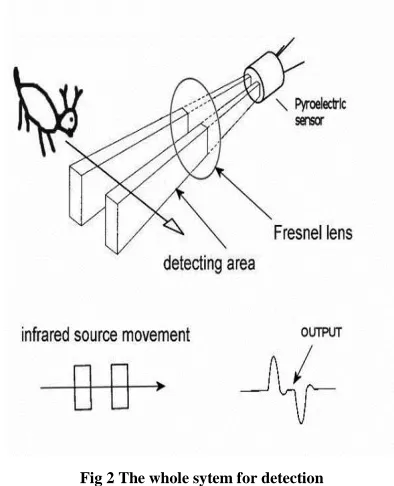
A body passing in front of the sensor will activate first one and then the other element whereas other sources will affect both elements simultaneously and be cancelled.
The radiation source must pass across the sensor in a horizontal direction when sensor pins 1 and 2 are on a horizontal plane so that the elements are sequentially exposed to the IR source. A focusing device is usually used in front of the sensor.
The focusing device consists of : 1) fresnel lens. 2) shadow lens. 3) pinhole lens. 4) infrared window.
The figure(2) shows the use of the whole system to detect a movement.
The total cost of the components to realize the proposed sensor is about rs35000 and this cost will be reduced in an industrial production. So in its final version the sensor node cost will be as low as rs.1700.
Fig 2 The whole sytem for detection
ii.iii Bluetooth based Insects, pests and disease detection in crops using visual sensor node:
Approach to this work
The proposed sensor is designed to reduce at minimum the power consumption and grant the necessary bandwidth to support image transfer and reduction of cost.
[image:2.612.69.269.426.627.2]International Journal of Emerging Technology and Advanced Engineering
Website: www.ijetae.com (ISSN 2250-2459, Volume 2, Issue 6, June 2012)94
The proposed sensor nodeThe hardware of a sensor node consists of eight components: sensing device, triggering circuit, passive voltage multiplier circuit, processor, memory, blue tooth module, R.F antenna module and a power supply. As shown in the figure.(e), also the proposed architecture can be divided in seven main blocks, each one is developed taking into account the low power consumption requirement since the nodes will be operating in unattended scenario,the power consumption should be kept to minimum to increase the life time of the network. First the individual model are discussed below:
(1) We use a ccd camera with the following specifications: A/D converters: Model 12: 12-bit
Readout rates: User set at 50K, 100K,200K pixels/sec
500K pixels/sec 8 bit focus
Readout noise: Less than 10 e-/read @100K pixels/second
CCD thermoelectric Model 45: -45C cooler performance
at 15C ambient
CCD temp. control: +/- 0.2 deg. C over a user-set range of -80 to +28C in 1/2 deg C
increments.
Mechanical shutter: Built-in. 1/20 sec. min. cycle.
Lens mount: Nikon standard. Tripod mount: 1/4-20 thread. Window: Fused silica with broadband anti-reflective coating.
Cam/computer cable: 50 ohm RG58C/U Cam/power supply 25' max. 10' std.
cable: Coax. 300' max. 25'std. computer I/O card: 16-bit ISA bus. 1/2 length card.
Camera head: 5"(w) x 6.2"(h) x 6"(d) Weight: 6 lbs.
Power supply: 7"(w) x 4.6"(h) x 10"(d) Weight: 6 lbs.
Power: 120-240 VAC 50/60 Hz 150 W max
Computer 80486 or Pentium, RAM: 32M min
The digital video port supplies a continuous wide image data. The adopted camera has many interesting features, some of which are controlled using four bits register-based commands. Regarding with the on-chip programmable features, these include the variable frame rate, the exposure setting, the gain control and the gamma correction. These functions may be very useful to allow good acquisitions in different operative conditions.
The cost of the CCD camera is Rs.1500
(2) Heart of the proposed sensor node is the microcontroller module. Among the others its main functions are the generation of 5v output which is fed to a voltage doubler circuit which triggers the relay switch and which in turn cause the relay switch to control the sensing element, the synchronization of the data transfer between sensor and memory, the control of the saved data transmission on the wireless channel. The processor module has been realized using a Intel 8051 low power microcontroller.
The intel 8051 micro-controller which is used here has the following important features and applications:
*It provides many functions (CPU, RAM, ROM, I/O, interrupt logic,
timer, etc.) in a single package
*8-bit data bus - It can access 8 bits of data in one operation (hence it is an 8-bit microcontroller)
*16-bit address bus - It can access 216 memory locations - 64 kB each of RAM and ROM
*On-chip RAM - 128 bytes ("Data Memory") *On-chip ROM - 4 kB ("Program Memory") *Four byte bi-directional input/output port *UART (serial port)
*Two 16-bit Counter/timers *Two-level interrupt priority *Power saving mode
A very useful feature of the used microcontroller is the possibility to operate in a low power consumption mode (Sleep mode), during this phase the normal I/O processor activities are stopped and the maximum current required from the device is less then 0.1 uA.
The cost of the processor module is Rs.900
(3) The memory module is constituted of a 256Mb DDR RAM PC2100 DDR266 device.
The RAM used here has the following specifications: # 256Mb modules (512Mb also available)
International Journal of Emerging Technology and Advanced Engineering
Website: www.ijetae.com (ISSN 2250-2459, Volume 2, Issue 6, June 2012)95
# Single-sided# 8 chips, 32MX64 DDR # 184 Pin Dimm
# Component composition: (32MX8)*8 # 2 years warranty
The FIFO architecture has been choose to reduce at minimum both the digital I/O pins used in the communication with the microcontroller and the addressing time. The main characteristics of the selected ram are a high speed asynchronous serial access and read/write cycle time of about 25.40 ns. The memory provides 8 digital input and 8 digital output lines, the first have been connected to the sensing hardware, while the latter have been connected to the processor module. Also the selected memory assures the required feature of low power consumption in fact it requires about 200 mA during the writing/reading operations and is practically zero during the standby
The cost of the memory module is Rs.700
(4) The Transceiver module is composed by two main parts: (a) the BT transmission module and (b) the radio frequency (RF) module.
(a) The BT transmission module is a 1.1 compliant Master/Slave module. This is a class 1 power (100 m) module and allows multiple interfaces for different applications. A TTL compatible RS232 communication channel assures the communication with the processor module. The selected module allows a 3.3V power supply and has a power consumption of about 400m W during the connection phase.
(b) The RF module is a very low cost micro amps RF receiver. The module range is up to 1 km and the current consumption is about 70 uA at 3.3 V. The data output of the RF module is connected with a suitable decoder module able to transform the received pattern in a variation of a digital line.
The RF module is indispensable because the BT module has considerable power consumption also in the standby mode and this does not match with the requirements of reduction of the over all power consumption to allow long term duration of the sensor’s node battery package.
For these reasons, if the master module requires an acquisition, then the communication between slave and master must be enabled else the sensor node has no operations to perform. During the no operation time the sensing hardware, the FIFO memory and the BT module can be turned off, while the microcontroller is set in the standby mode.
When an acquisition has to be performed the master module wakes up the RF module that generates an interrupt able to set the microcontroller in the active state; then all the normal operations can start. This procedure makes possible to save much energy and allows reducing the power consumption as better described in the following. The decoder has been used in order allowing a selective sensor node wake up. The implementation of the wake up procedure might be realized also using software routines, but this solution would have required to keep the microcontroller in active state thus reducing the energy saving.
The cost of the overall transmission section is about Rs.2000.
(5) The battery package consists of dual D-lithium battery pack. Due to its lithium technology, the output of the pack is strong and stable throughout the life of the battery At the end of the battery life, clocks respond to signal change by five stepping(the second hand will step at five seconds interval).The battery pack is completely sealed for safety and provides optimal performance for at least five years.
The specification of the dual D-lithium battery pack is given below:
• Battery Pack contains two Lithium Primary Batteries • Nominal Voltage = 3.6 volts
• Nominal Capacity = 9.00 Amp x hours each (Total = 18 Ah)
• Maximum Current: 200 ma
• Self Discharge = less than 1% after year of storage • Hermetic glass to metal seal
• Stainless steel internal container
• Compliant with IEC 86-4 Safety Standard and EN 50020 intrinsic safety
• Directly replaces two “D” alkaline batteries in battery operated analog clocks
• A minimum of 5-year life, under normal room temperature conditions.
• Operating Temperature Range: -55°C to + 85°C ( -67°F to +185°
• Storage Temperature: Recommend 30°C max. /Extremes: -55°C min. +100°C Max. [17]
The cost of the battery pack is approximately Rs.1000.
International Journal of Emerging Technology and Advanced Engineering
Website: www.ijetae.com (ISSN 2250-2459, Volume 2, Issue 6, June 2012)96
The circuit is designed as two diodes connected back to back with one capacitance being in series with the diodes and the other one is connected as parallel with the diodes as shown in the figure.The total building cost of the circuit will be approximately Rs.50.
(7) The circuit which basically triggers the sensing camera is called the triggering circuit. Here a 12v relay switch(refer to the figure ) is used as a triggering circuit to trigger the camera when a 10v supply comes from the voltage doubler circuit. When the weather station gives out a signal ,the BT module receives it. It then sends a signal [5v for intel 8051 micro controller] which is doubled by a multiplier circuit. The multiplier circuit doubles the incoming 5V signal to10v which then triggers the 12v relay switch to turn the CCD camera of the sensor node on and take images.
The relay switch will cost Rs.100
Working principle
Fig.(3) shows a block diagram of possible states in the proposed acquiring procedure together .
Fig 3 Block diagram of a wireless blue tooth sensor node.
The acquiring procedure can be described as follows: (1) The weather station will calculate the possible time zone during which pests, insects can grow or diseases may happen in the crop system. After calculation of the risk factors, the weather station will send a signal to the central server station which in turn will send data stream [i.e a pulse signal] to the RF transceiver module of the sensing node. The arrival of a data stream on the RF module will start the activation of the decoder module. If the stream matches the decoding sequence the activation of a microcontroller interrupt will be obtained.
(2) Subsequently a wake up service routine generated by the decoder will turn the microcontroller on and will start the acquisition process. The first operation done by the microcontroller will be to activate the BT module and the RAM memory. It will also generates an output of 5V, which will be fed to the passive voltage multiplier circuit .All the required reset and self-test operations will be made by each device, which is set in a ready status.
(3) The microcontroller will perform all the operations which are necessary to establish the communication with the BT module. In particular the microcontroller lets the BT module in a discoverable status and successively a master to slave connection is obtained between the sensor and a remote data acquisition station.
(4) Successively the microcontroller sets all the required parameters on the voltage multiplier circuit which will double the incoming voltage generated by the microcontroller. The circuit will produce an output of around 10V which will be fed to the 12V RELAY switch.
(5) When the output 10V of the passive voltage multiplier circuit is fed to the 12V RELAY switch, then the relay switch will be activated. The relay switch in turn will activate the CCD camera and allows the starting of the image acquisition and the transferring of the acquired pixels on the 256Mb RAM memory..
(6) When all the image pixels will be written on the RAM , the microcontroller will generate suitable BT packets and will transmit the overall information to the master module.
(7) At the end of the acquiring and transmission process the microcontroller will wait for a suitable time if new acquisition are needed and then becomes inactive. On the contrary all the previously powered on devices are turned off and remains in the sleep mode.
[image:5.612.60.279.391.680.2]International Journal of Emerging Technology and Advanced Engineering
Website: www.ijetae.com (ISSN 2250-2459, Volume 2, Issue 6, June 2012)97
Apart from the cost reduction, since the camera and the associated circuitries are generally kept in reset or sleep mode, The power drain will be minimum and the nodes will only draw power in case of external activation by the central server or by the local low cost insect detection trap. Since we have selected a long lasting battery pack (life span of five years) and we are using it spuriously, the life time of the sensing node will be much higher.III. CONCLUSION
This paper deals with detecting disease and pests in crops by receiving signals from the base station and then taking a photo using CCD camera and sending it over to the base station via a Bluetooth module for verification. Future prospect of this paper could be creating a system which would be able to auto detect the pest and diseases in the crops and then send an alert signal directly to the base station.
Motion sensors and sensors that can differentiate between colors could be used for this purpose.
Though this new design might be a bit expensive than my proposed design but it would definitely save time and hence the design would be much more efficient.
REFERENCE
[1 ] D.FAMOLARI,P.AGARWAL, "architecture and performance of an
embedded IP Bluetooth personal arean network", 2000
IEEE,international conf. on personal wireless communication [2 ] L.FERRIGNO,A.PIETROSANTO, "a bluetooth base proposal of
instrument wireless interface" IEEE,nterntionl symposium,virtual and intelligent measurement system
[3 ] Intel: http://www.intel.com/design/mcs51/docs_mcs51.htm [4 ] Michigan state university: http://www.grapes.msu.edu/pestGDD.htm
[5 ] Insect lists,ohio: http://ohioline.osu.edu/b545/pdf/b545.pdf [6 ] Plant disease: http://www.tarahaat.com/PlantDiseases.aspx
[7 ] DEBORAH ESTERIN,LEWIS GIROD,GREG POTTIE,MANI
SRIVASTAVA, instrumenting the world with wireless networksin proceedings of the international conference on accoustics,speech and signal processing(ICASSP,2001),salt lake city,utah,may 2001 [8 ] H.GHAVRI,K.BAN "video based multihop and ad hoc sensor
network design" in 2002 world wireless congr.,may 2002
[9 ] L.FERRIGNO,A.PIETROSANTO,"a low cost visual sensor node for
blue tooth based measurement networks",IMTC
2004,instrumentation and measurement technology conference.
[10 ]How Infrared motion detector components work:
http://www.glolab.com/pirparts/infrared.html [11 ]Cryocam:
[12 ]http://www.microluminetics.com/specs.htm [13 ]Intel 8051:
[14 ]http://en.wikipedia.org/wiki/Intel_8051 [15 ]MCS 51/251microcontroller:
http://www.intel.com/design/mcs51/docs_mcs51.htm
[16 ]Basic introduction to the 8051 microcontroller:
http://www.cs.ucr.edu/~dalton/i8051/
[17 ]Types of RAM: How to Identify and their Specifications: http://www.technibble.com/types-of-ram-how-to-identify-and-their-specifications/2/
[18 ]Available rams in market:
http://www.shop4memory.com/products/memory-specification.asp [19 ]Dual d lithium batteries:
http://www.primexwireless.com/data/spec_corner/cut_sheets/gps_sy nc_soln/usca/battery.pdf