© 2017, IRJET | Impact Factor value: 5.181 | ISO 9001:2008 Certified Journal | Page 554
Design and Analysis of Multi Spindle Drilling Head with
Adjustable Centre Distance
Sainath Patil
1, Dr. S. R. Basavaraddi
21
Post Graduate Student, Department of Mechanical Engineering, KLEMSSCET, Belgaum, Karnataka, India
2Professor, Department of Mechanical Engineering, KLEMSSCET, Belgaum, Karnataka, India
---***---Abstract -
Most of the local brake part manufacturingindustries in developing countries like India, still drill holes in casting part make by two or more drilling head on two or more number of machine. This accumulation constitutes a space problem and encourages idle time. A gang-drilling (or a multiple spindle drilling) machine that could perform all the drilling operations in one operation. In response to this, a Multiple-Spindle Drilling Head (MSDH) is designed. The machine was designed as an attachment (accessory) to a main drill from which it drives the power for its operations.
Multi spindle head machines are used in mechanical industry in order to increase the productivity of machining systems. Such machines are equipped by spindle heads that carry multiple tools for performing machining operations. The most noteworthy aspect when using multi-spindle machines is the cycle time, due to parallel machining the total operating time is dramatically decreased. Added benefits include less chance for error, less accumulated tolerance error, and eliminate tools changes. In such a multi-spindle machine, a part to be machined is fixed on the table.
Key Words: Multi Spindle Drilling Attachment, Gear, Spindle, Shaft, Drill Holder Design, Analytical Calculations, Static Analysis.
1.INTRODUCTION
Drilling is the most generally perceived machining process whereby the operation incorporates making round openings in metallic and non-metallic materials. Around 75% of all metal-cutting method is of the drilling operation. Drills generally have a high length to diameter proportion that is fit for making significant hole, however as a result of its flexibility, vital security measure ought to be taken to keep up accuracy and keep drill from breaking.
Drilled holes can be either through holes or visually blind holes. A through holes is made when a drill leaves the inverse side of the work; in blind hole the drill does not leave the work piece. During the operation, chips that are created inside the work piece must exit through the flutes to the outside of the device. As the chip is formed and removed towards the surface, it will produce friction. Friction subsequently warm is likewise created when the drill bit
touch the work piece during the hole making process. In this way, chip transfer and cutting fluids are among the most essential components should be consider during this procedure. Regularly, holes created by drilling are greater than the drill diameter and relying upon its applications; the drilled holes will subjected to different operations, for example, reaming or sharpening to better surface complete and dimensional exactness.
1.1 Types of Drilling Machine
Based on construction
Portable drilling machine Sensitive drilling machine Radial drilling machine Up right drilling machine Gang drilling machine
Multi spindle drilling machine
Based on feed
Hand power drilling machine Power driven drilling machine
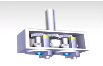
[image:1.595.351.519.559.667.2]3.3 Principle of Multi spindle Drilling Head
Fig -1.1: Multi Spindle Drilling Head
© 2017, IRJET | Impact Factor value: 5.181 | ISO 9001:2008 Certified Journal | Page 555 2. The spindles are so constructed that their centre distance
can be balanced in any position within the drill head depending upon the job requirement. For this reason, Allen bolt is used.
3. The power from the motor is transmitted by spindle to the centre gear. After that power at centre gear is transmitted to the drilling spindle by compound gear train.
1.2. Problem Definition
In the conventional manner just a single job can be worked at once for both of the above operations, however with increase in productivity demands a special purpose device or attachment is need which will increase productivity by,
1. Performing operations on more than one job at a time.
2. Performing multiple operations in one cycle.
3. Indexing capability to sequence operations one after another.
1.3 Solution
The multi-spindle drilling attachment is a perfect answer for the above issue. Where the regular drilling machine is utilized to perform three operations at any given moment, so likewise different operations like boring, reaming, countersinking or spot confronting should be possible by using multi spindle drilling attachment.
1.4 Objectives
Manual design calculations of spindle and shaft.
Manual design calculations of main gear and compound gear.
Manual design of drill holder and bush bearing.
Manual design of Multi Spindle Drilling Head for adjustable centre distance.
Modeling of all the parts in CATIA.
Analysis using ANSYS.
Comparison of results.
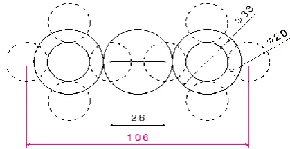
1.5. Centre Distance
[image:2.595.329.539.111.219.2]Centre distance can vary within the range of 26mm to 106 mm. This is shown in below figure.
Fig -1.2: Range of centre distance
2. DESIGN AND CALCULATIONS
2.1 Selection of Prime Mover
Diameter of hole (d) = 4 mm & 5 mm Thickness of the plate (t) = 8 mm Work piece material = Cast Iron
Power = {1.25×D2×K×N×(0.056+1.5×Fn)}/105 For ø4 mm
Power = {1.25×42×1.5×720×(0.056+1.5×0.0635)}/105 Power = 0.032 kw
For 2 Spindles = 0.032×2 = 0.065 kw Power = 0.088 HP
For ø5 mm
Power = {1.25×52×1.5×720×(0.056+1.5×0.0635)}/105 Power = 0.051 kw
For 2 Spindles = 0.051×2 = 0.1 kw Power = 0.13 HP
Total power required = 0.13+0.13 = 0.277 HP Therefore 0.5 HP motor is required.
2.2 Design of Spindle
Consider diameter of spindle = 16 mm Material of spindle = Mild steel P = 2πNT/60
T = (367.5×60)/(2×π×720) T = 4874 N-mm
Consider 25% overload T = 6092 N-mm
D = {(16/π×τ)×Kt×Mt}0.33 16 = {(16/π×τ)×2×6092}0.33 τ = 15.14 N/mm2
© 2017, IRJET | Impact Factor value: 5.181 | ISO 9001:2008 Certified Journal | Page 556 Fig -2.1: CATIA Model of Spindle
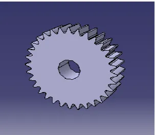
2.3 Design of Big Gear
Material of gear = EN 24
Consider diameter of gear (d) = 33 mm Consider Module = 1 mm
No. of teeth = 33 From Lewis equation, σ = {Ft/(Cv×b×Y×m)}
σ = {370/(0.7102×8×0.3967×1)} σ = 164.16 N/mm2
[image:3.595.357.510.276.390.2]The induced stress value is 164.16 N/mm2. This value of stress is very less as compared to yield stress of gear material. ( 680 N/mm2 ) Therefore designed gear is safe.
Fig -2.2: CATIA Model of Big Gear
2.4 Design of Small Gear
Material of gear = EN 24
Consider diameter of gear (d) = 20 mm Consider Module = 1 mm
No. of teeth = 20 σ = 279.29 N/mm2
The induced stress value is 279.29 N/mm2. This value of stress is very less as compared to yield stress of gear material. ( 680 N/mm2 ) Therefore designed gear is safe.
2.5 Design of Shaft
Material of Shaft = Mild Steel Outer diameter of shaft = 14 mm Inner diameter of shaft = 8 mm
Torque transferred to the shaft = 6092 N-mm For Shear Stress,
D0 = {(16/π×τ×(1-K4))×Kt×Mt}0.33 14 = {(16/π×τ×(1-0.5714))×2×6092}0.33 τ = 25.31 N/mm2
[image:3.595.86.238.440.572.2]The induced shear stress value is 25.31 N/mm2. This value of shear stress is very less as compared to yield stress of shaft material. ( 415 N/mm2 ) Therefore designed shaft is safe.
Fig -2.3: CATIA Model of Spindle
2.6 Design of Drill Holder
Material of Drill Holder = Mild Steel Diameter of Drill Holder = 8 mm For shear stress,
D = {(16/π×τ)×Kt×Mt}0.33 D = {(16/π×τ)×2×6092}0.33 D = 121.19 N/mm2
The value of shear stress is 121.19 N/mm2. This is very less as compare to yield stress of drill holder material. (415 N/mm2 ) Therefore designed drill holder is safe.
[image:3.595.357.514.580.696.2]© 2017, IRJET | Impact Factor value: 5.181 | ISO 9001:2008 Certified Journal | Page 557
3. ANALYSIS
[image:4.595.323.548.101.233.2]3.1 Spindle Analysis
[image:4.595.57.266.139.299.2]Fig -3.1: Total Deformation in Spindle
Fig -3.2: Maximum Shear Stress in spindle
Torque of 6092 N-mm is applied to spindle and obtained shear stress value is 21.89 MPa which is very less compared to yield stress of material ( 415 N/mm2 ). So it is safe under shear stress condition. The total deformation observed in the spindle is 0.0097 mm.
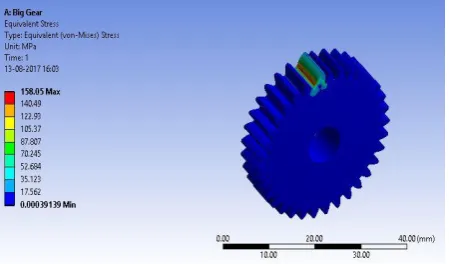
3.2 Big Gear Analysis
[image:4.595.55.269.332.466.2]Fig -3.3: Total Deformation in Big Gear
Fig -3.4: Equivalent Stress in Big Gear
Force of 370 N applied on gear tooth as shown in figure 5.16 above. Induced equivalent stress is 158.05MPa this value is below yield stress (680MPa) of material therefore gear design is safe. The total deformation observed in the big gear is 0.0032 mm.
3.3 Small Gear Analysis
Fig -3.5: Total Deformation in Small Gear
Fig -3.6: Equivalent Stress in Small Gear
[image:4.595.320.549.365.509.2] [image:4.595.319.548.547.699.2] [image:4.595.53.272.596.745.2]© 2017, IRJET | Impact Factor value: 5.181 | ISO 9001:2008 Certified Journal | Page 558 design is safe. The total deformation observed in the big gear
is 0.0044 mm.
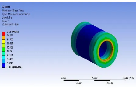
3.4 Shaft Analysis
[image:5.595.322.550.100.260.2]Fig -3.7: Total Deformation in Shaft
Fig -3.8: Maximum Shear Stress in Shaft
Torque of 6092 N-mm is applied to shaft and obtained shear stress value is 27.64MPa which is very less compared to yield stress of material ( 680 N/mm2 ) so it is safe under shear stress condition. The total deformation observed in the shaft is 0.00049 mm.
[image:5.595.53.274.159.293.2]3.5 Drill Holder Analysis
[image:5.595.49.273.325.470.2]Fig -3.9: Total Deformation in Drill Holder
Fig -3.10: Maximum Shear Stress in Drill Holder
Torque of 6092 N-mm is applied and obtained shear stress value is 107.98MPa which is very less compared to yield stress (415MPa) of material so it is safe under shear stress condition. The total deformation observed in the drill holder is 0.025 mm.
[image:5.595.320.545.389.563.2]3.6 Assembly Analysis
Fig -3.11: Total Deformation in Assembly
[image:5.595.111.535.599.749.2]© 2017, IRJET | Impact Factor value: 5.181 | ISO 9001:2008 Certified Journal | Page 559 All the values of stresses are below yield stress of the
material (415MPa) so assembly is safe under all the loading conditions. . The total deformation observed in the assembly is 0.100 mm.
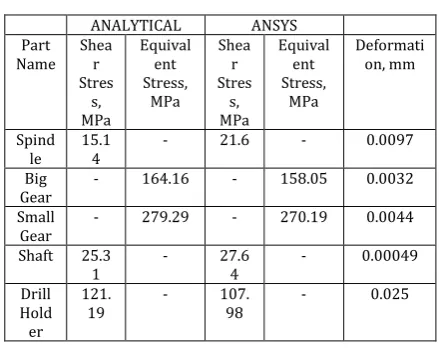
4. Comparison of Results
[image:6.595.51.271.282.456.2]In this project various parts of multi spindle drilling head attachment have been analyzed as above. The static analysis is done to study the deformation and stresses induced in the parts. Analytical design calculations is also done by using various design formulas. Comparison of static analysis results with analytical results is done which is given below.
Table 4.1: Comparison of Results
ANALYTICAL ANSYS
Part Name Shear
Stres s, MPa Equival ent Stress, MPa Shea r Stres s, MPa Equival ent Stress, MPa Deformati on, mm Spind le 15.1 4
- 21.6 - 0.0097
Big
Gear - 164.16 - 158.05 0.0032
Small
Gear - 279.29 - 270.19 0.0044
Shaft 25.3
1 - 27.64 - 0.00049
Drill Hold er
121.
19 - 107.98 - 0.025
5. CONCLUSION
The results obtained through analytical design calculations of the various parts of multi spindle drilling attachment are compared with the yield stress of that material for safe design. And static analysis is done which is compared with analytical results. Results shows the values of deformation, shear stress and equivalent stress and these values are below yield stress of the material. Therefore all the parts are safe under all the loading condition. In comparison of analytical and ANSYS results both results are close to each other. Hence by looking into this results stresses and deformation are within the limit therefore multi spindle drilling head attachment design is safe.
With the help of this attachment, one can drill two holes at a time with provision of varying centre distance between two drilling spindle. Using multi spindle drilling attachment increase productivity at low cost and in less time, cycle time is also reduced. With the help of this design and analysis it is possible to develop three or four spindle drilling machine attachment.
REFERENCES
[1] Prof. P.R. Sawant and Mr. R. A.Barawade, “Design and
development of SPM-a case study in multi drilling and tapping machine”, International Journal of Advanced Engineering Research and Studies.Volume 1, Issue 2, January-March, 2012, 55-57.
[2] Mr.K.K.Powar, Prof. (Dr) V.R.Naik and Prof.G.S.Joshi,
“Optimization of process parameter for multispindle drilling machine by using taguchi method”, International journal of advanced technology in engineering and science, Volume No.03, Issue No. 03, March 2015.
[3] Prof.M.B. Bankar, Prof. P.B. Kadam, Prof. M.R. Todkar,
“Improvement in design & manufacturing process of multiple spindle drilling attachment”, IOSR Journal of Engineering, Volume 3, Issue 1, Jan 2013, 38-43.
[4] M. Narasimha, R. Reji Kumar, R. Srinivasa Moorthy,
“Design of adjustable multi-spindle attachment”, International journal of engineering research and development (IJERD), Volume 4, Issue 2, May – August 2013.
[5] Prof. K.G.Sontakke, Prof. R. D. Vaidya and Prof. D.M.
Mate, “Design and analysis of drilling cum riveting Machine”, Journal of emerging technologies and innovative research (JETIR), Volume 1, Issue 6, ISSN-2349-5162, Nov 2014.
[6] [] Pratik Parsania, Prof. Jignesh Dave and Brijesh Garala,
“Design of hydraulic power pack for SPM (Multi Spindle Drilling)”, Indian journal of applied research, Volume 3, Issue 6, ISSN - 2249-555X , June 2013.
[7] Sushil S. Vadnere, Ajinkya A. Deshmukh, Surjeetsingh R.
Chauhan and Asst. Prof. Ramesh V. Bhandare, “Design and analysis of a multi spindle drill gearbox”, International journal on recent technologies in mechanical and electrical engineering (IJRMEE) , Volume 1, Issue 4, ISSN: 2349-7947.
[8] Bajirao H. NangarePatil, and Prof. P. R. Sawant, “Design
And Development Of Gearbox For Multi-Spindle Drilling Machine (SPM)”, International journal of engineering research & technology (IJERT) Volume 2, Issue 5, ISSN: 2278-0181, May-2013.
[9] Chukwumuanya, Emmanuel O, Obuka, Nnaemeka