© 2018, IRJET | Impact Factor value: 6.171 | ISO 9001:2008 Certified Journal | Page 3539
Study on Different Types of Controlling Techniques Used For
Interleaved DC-DC Boost Converters
Mrunali J. Panse
1, Rakesh G. Srivastava
21
M.Tech 4
thSem. Student, S.D.C.O.E., Wardha, Maharashtra
2
Professor, Dept. of Electrical Engineering, D.M.I.E.T.R., Wardha, Maharashtra
---***---Abstract -
DC - DC boost converter were used in manyapplications such as renewable energy sources which includes photovoltaic ( PV ) cells and fuel cells. The reliability, efficiency and controllability of PV systems can be increased by using Boost converters. A DC - DC Boost converter provide higher output voltage but it produces some ripple current. In order to reduce the ripple current so as to improve the efficiency of boost converter, an interleaved boost converter is used. For maintaining the voltage at output constant irrespective of variations in DC input voltage and load current, a control system must be required for the interleaved converter. This paper presents a detailed study of various control techniques of DC - DC interleaved Boost for conversion of power from one level to another level. In addition, these control techniques are compared in terms of their advantages and dis-advantages.
Key Words:DC-DC Interleaved Boost converter(IBC), PID control, Slide – Mode Control ( SMC ) and Sigma – Delta ( SDM )
1. INTRODUCTION
In recent years, renewable energy sources have become the fastest growing power sector in the world. Conventional fossil-fuels take millions of years to completely restore. It also has limited reserve capacity and costs for high price. Due to this reason, renewable energy sources are the possible solutions to the environmental problems. In research fields, most of the renewable energy sources such as fuel cell stacks and photovoltaic cells have received worldwide attention. [1]
A switching converter is a power electronic devices which is used to transform an input voltage level into another level by switching action of semiconductor device. For this purpose a high power dc-dc converter is strongly required that has found widespread applications like aerospace, electric vehicle (EV), portable electronic device like pagers and microprocessor voltage regulation.
Power electronic based DC – DC converter interfaces for DC energy sources, but these power sources have quite low voltage output.
Most of the renewable power sources, have quite low-voltage output and to increase its output level, it requires series connection or voltage booster [4]. DC-DC boost
converters are generally employed in equipment, as pre-regulators [8]–[10]. But, due to the inductor of classical boost converter, the ripple current is increased.
Interleaved boost converter IBC, is one such converter that can be used for high power applications. The advantages of interleaved boost converter are faster transient response, high efficiency, improved reliability and decreased electromagnetic emission. Due to interleaved operation ( parallel connection of two or more boost converter ), IBC proposes both lower current ripple at the input side and lower voltage ripple at the output side. Few literatures related to the controller design so as to obtain high performance control of high-power interleaved boost converter can be found [2].
In this paper different control techniques, including linear and non-linear control such as current mode control, voltage mode control, PWM with PID control, slide mode control, digital control Sigma-Delta modulator, fuzzy control, for DC-DC boost converter have been studied. Fuzzy controller is non-linear controller that is effective but is difficult as well as expensive for practical application. Now a days, current-mode controllers and linear control methods are most frequently used for controlling DC-DC boost converter.
2. MODELLING AND DESIGN OF DC – DC
BOOST CONVERTER
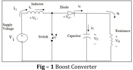
[image:1.595.322.545.614.731.2]A boost converter is known as step – up converter. The circuit of dc – dc boost converter is shown in Fig. 1. It step up the input voltage Vi and provides high output voltage Vo at the output side, for steady – state operation. It ‘ boost ’ the voltage to a higher level. Hence, Vo is always higher than Vi.
Fig – 1 Boost Converter
© 2018, IRJET | Impact Factor value: 6.171 | ISO 9001:2008 Certified Journal | Page 3540 C configured in parallel to a resistive load R. The switch is set
to ON and OFF state at a switching frequency fs = 1/T with duty ratio D = ton/T, where ton is the time interval when switch S is at ON state [3]. It is a class of switching mode power supply (SMPS) containing at least two semi-conductors switches (a diode and a transistor) and at least one energy storage element. The capacitor is connected at the output side as the ripples present in output voltage is reduced [5]
Boost converter is said to operate in two modes, they are as follows :
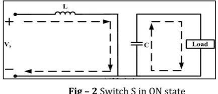
1) Mode 1 :
[image:2.595.44.261.289.383.2]When the switch S is closed i.e. ON state, causes the current in the boost inductor increases linearly, storing energy in its magnetic field. During this mode of operation, the load is completely isolated from source, as shown in Fig. 2
Fig – 2 Switch S in ON state
Transistor switching period is given as, Ton DTp
(1)
Voltage across the inductor,
(2)
V
dt
di
L
i2) Mode 2 :
When the transistor switch S is open i.e. OFF-state, energy stored in the inductor is released through the fly-back diode D to the input RC circuit. Voltage across the boost inductor L and the source Vi, charges the capacitor C and also supplies the energy to the load R [6]. The conduction path is as shown in Fig. 3
Fig - 3 Switch S in OFF state Transistor switching period is given as,
Toff D )Tp (3) Voltage across the inductor,
)
Vo
(Vi
-dt
di
L
(4)When the switch is open, the voltage across the inductor is:
o i
L
V
V
v
(5)After rearranging the equations (1),(2),(3) and (4),we get
i p
V DT
Δi
L (6)
i o p
V V D)T (1
Δi
L
(7)
Hence when the switch is held OFF, the change in inductor current can be computed as shown in eqn. (8)
p i
o
L (1 D)T
L V V
Δi (8)
On solving equation (6) and (8), it yields
D 1
1 V Vo
i
(9)
Equation (9) reflects the fact that a large duty ratio is required for a large voltage boost. Therefore, in order to maintain acceptably small output ripple voltages, a prohibitively large capacitance is required to ensure that the output voltage does not sag . Also, since both dc and ac current are being sourced through the inductor, the inductor must be designed such that the cores will not saturate during high power operation. Thus, it is concluded that boost converter requires large output filter capacitor to reduce current ripple and hence not suitable for high power generation.
Due to the disadvantages of boost converter listed above, there arise the need for efficient boost converter which can improve the efficiency and in other hand it should give low input and output ripples. The invention of Interleaved Boost Converter satisfies the above demand.
3. INTERLEAVED BOOST CONVERTER
Interleaved boost converter is a promising interface between distributed energy sources such as fuel cells, PV, battery and the DC bus of inverters. Due to interleaving operation, IBC exhibits both lower current ripple at the input side and lower voltage ripple at the output side.
Therefore, the size and losses of the filtering stages can be reduced, and switching losses can be significantly decreased [7].Paralleling two or more switching devices is a widely utilized approach to increase the current handling capability of switches. The advantages of the parallel converters scheme is to implicit proper design, dynamic response, robustness and tight steady state[13-15].
© 2018, IRJET | Impact Factor value: 6.171 | ISO 9001:2008 Certified Journal | Page 3541
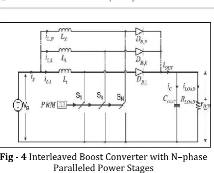
Fig - 4 Interleaved Boost Converter with N–phase Paralleled Power Stages
In a two-phase converter, there are two output stages that are driven 180 degrees out of phase. By splitting the current into two power paths, conduction (I2R) losses can be reduced, increasing overall efficiency compared to a single-phase converter.
In three-cell dc/dc converter architecture, the cells are switched with the same duty ratio, but with a relative phase shift or time interleaved of 120° introduced between each cell in order to reduce the magnitude of the ripple at the output port of the converter[16].
4
.CONTROL TECHNIQUES
To ensure stability as well as fast transient response of interleaved Boost Converter Several control techniques have been proposed namely - Fuzz Logic controller, Artificial Neural Network (ANN), PID controller and PI controller. Several Optimization techniques such as Genetic Algorithm, Particle Swarm Optimization, and Bacterial Foraging Optimization have also been proposed.
Different control techniques, including linear and nonlinear control, such as current mode control, PID control and sliding mode control (SMC), model predictive control, fuzzy control, hybrid control and sigma-delta modulation, for DC-DC boost converters have been discussed.
A.
Proportional, Integral, Differential Controllers
(PID)
In various industrial applications proportional, integral and differential controllers organization is most commonly use to improve the performance of the selected control system. Various combination of proportional (P), integral (I) and differential (D) controllers are shown below:
a) Proportional and Integral Controllers (PI)
b) Proportional and Derivative controllers(PD)
c) Proportional Integral and Derivative Controllers
One of the simplest and most widely used controller for decades is the PID controller. PID stands for proportional (P), integral (I) and derivative (D) controller. Fig. 5 shows the block diagram of a typical PID controller. Proportional derivative (PD) controller improves the transient response of the system. Proportional integral (PI) controller reduces steady state error present in the system.
Fig - 5 Typical PID control Structure
The combination of PI and PD controller forms the PID controller, it involves P, I and D three different constant parameters. Signal which is present in between desired output and actual output is an error signal. PID controller operates directly on error signal. Advantages of PID controller are as faster response to change in the control input; control signal increases to lead steady state error towards zero and eliminates oscillations. By tuning the three constant the controller can provide the control action for the specific process. the factors on which the response of the controller depends are the responsiveness of controller for error, degree of system oscillation and the degree at which
cont
roller overshoots the set point
.Advantages of PID controllers
PID controller is independent of the system model, simple design and is applicable for various fields. Thus, has a predominant role in industrial control. Very fast response for change in the control input control signal increases to lead steady state error towards zero also eliminates oscillations.
Disadvantages of PID controllers
As the PID controller technique cannot meet increasing requirements for fast dynamic response it leads to high control precision. If there occurrence of uncertainties then the stability of this technique cannot be guaranteed.
B.
Sliding Mode Control
Power electronic converters such as DC-DC converters mostly used. By changing the duty cycle of the switches in the circuit converter the sources of direct current changes from one voltage to another voltage level. For the nonlinear system it’s become a great challenge for design and control. Classical control methods are not suitable for operating point variations and load disturbances. Large signal transient in the startup point and variations in the system parameters and large signal transient produce in the system output, only due to change in the load , cannot allocate with these techniques.
Advantages of sliding mode control
Sliding Mode Control is independent of disturbances and constraints. For large disturbances it can provide fast dynamic response and very simple implementation and stability. This can be achieved due to property of acting on all system state variables concurrently.
C. Sigma – Delta Modulation
[image:3.595.305.553.96.184.2]© 2018, IRJET | Impact Factor value: 6.171 | ISO 9001:2008 Certified Journal | Page 3542 improvement of an older Delta modulation (DM or
[image:4.595.59.265.187.273.2]Δ-modulation). Delta Modulator is an analog-to-digital modulation technique are generally used for a wide variety of applications, including digital wireless, digital telephony over the Internet (VoIP), and 4th generation mobile communications. The SDM consists of an integrator and a quantizer in a feedback loop, as shown in Fig. 7.
Fig - 7 Sigma – Delta Modulator Block Diagram
Advantages of sigma – delta modulation
Fast transient response. It provide high efficiency at low load. Spread spectrum of switching noise. It can operate at higher switching frequency and thus can use smaller L and C.
5. PROPOSED WORK
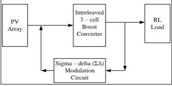
The proposed work is based on conversion of renewable energy sources into useful DC or AC power for residential and industrial applications and to acquire a suitable converter for it. The converter used is three phase interleaved dc – dc boost converter. In the proposed boost converter the voltage at the output of the converter is higher than the input. The proposed converter utilizes delta-sigma modulation to control pulse generator. A thorough and effective analysis of the converter is carried out in order to achieve the system stability and to improve the dynamic performance. The following block diagram illustrates the proposed work.
Intreleaved 3 – cell
Boost Converter
Sigma – delta (Ʃ∆) Modulation
Circuit
RL Load PV
Array
Fig - 6 Proposed work block diagram
6. CONCLUSION
The above paper is a review of various control techniques of Interleaved DC-DC Boost Converters. Different control techniques, including linear and nonlinear control, such as current mode control, PID control and sliding mode control (SMC), sigma-delta modulator, predictive control, fuzzy control, hybrid control, for DC-DC boost converters have been studied. Non-linear controllers like model predictive control (MPC) and fuzzy controllers are difficult and expensive for practical applications. Current mode controller
designing is not an easy task and the linear control effects are limited. PID Controller technique cannot meet increasing requirements for fast dynamic response, high control precision and if there are uncertainties then the stability of this technique cannot be guaranteed. Slide control method provide stability, against the large disturbance. It is very simple to implement and provide fast dynamic response, due to property of acting on all system state variables concurrently. SSDM control loop has very fast response and low ripples. With the phase shift of 120°, the output of the converter is found to be continuous. Due to the equal sharing of the load current between cells, reliability is improved, as the overwork on the semiconductor switches is reduced.
REFERENCES
[1] Cacciato M., Consoli A., Attanasio R., and Gennaro F. 2006.,“ A multi-stage converter for domestic
generation systems based on fuel cells”, In Proc. IEEE Ind. Appl. Soc. Conf., vol. 1, pp. 230–235.
[2] Xingyi Xu, Lizhi Zhu, “A DSP Based Controller for, High-Power Interleaved Boost Converters”, APEC'03, vol. 1, pp.327-333, 9-13 February 2003.
[3] Marian K. Kazimierczuk, “ Pulse–width Modulated DC–DC Power Converters ”, A John Wiley and Sons, Ltd, Publication 2008.
[4] Kobayashi K., Matsuo H., and Sekine Y.,2006., “Novel solar-cell power supply system using a multiple-input DC–DC converter. ” In IEEE Trans. Ind. Electron., vol. 53, no. 1, pp. 281–286.
[5] Lopamudra Mitra, Nibedita Sain, “ Closed Loop Control of Solar Powered Boost Converter with PID Controller”, IEEE International Conference on Power Electronics, Drives &Energy stem(PEDES), 2014
[6] Mirza Faud Adnan, Md. Abdul Moin Oninda, Mirza Muntasir Nishat, Nafiul Islam, “Design and Simulation of a DC – DC Boost Converter with PID controller for Enhanced Performance ”, IJERT, Vol. 6, 2017
[7] P. A. Dahono, S. Riyadi, A. Mudawari and Y. Haroen, ‘‘Output ripple analysis of multiphase DC–DC
converter’’. IEEE Int.Conf. Power Electrical and Drive Systems,Hong Kong, pp. 626–631, 1999.
[image:4.595.76.246.524.609.2]© 2018, IRJET | Impact Factor value: 6.171 | ISO 9001:2008 Certified Journal | Page 3543 In IEEE Trans. Power Electron., 2011 6th IEEE
Conference on Industrial Electronics and Applications vol. 21, no. 1, pp. 66–72. 2367
[9] Jang Y., Jovanovic´ M. M., Fang K. H., and Chang Y. M., 2006, “ High-power factor soft-switched boost converter”, In IEEE Trans. Power Electron., vol. 21, no. 1, pp. 98–104.
[10] K. P. Louganski and J. S. Lai, “Current phase lead Compensation in single-phase PFC boost converters with a reduced switching frequency to line
frequency ratio,” IEEE Trans. Power Electron., vol. 22, no. 1, pp. 113–119, Jan. 2007.
[13] Mazumder, S.K.,Nayfeh, A.H., Borojevic, A, “Robust control of parallel DC-DC buck converters by
combining integral-variable-structure and multiple-sliding-surface control schemes”, IEEE POWER ELECTR, (Volume:17,Issue: 3 ),May 2002, pp. 428 – 437.
[14] Tamyurek, B, Birdane, E, Ceyhan, A, “Design and implementation of an improved controller for parallel-connected 400 Hz frequency converters”, Twenty-Fifth Annual IEEE Applied Power Electronics Conference and Exposition (APEC), 2010 (Feb.2010), pp. 1197 – 1203.
[15] Kohama, T,Ninomiya, T, Shoyama, M, Ihara, F, “Dynamic analysis of parallel-module converter system with current balance controllers”, 16th International Telecommunications Energy Conference, 1994. INTELEC '94., 30 Oct-3 Nov 1994, pp.190 – 195