© 2016, IRJET | Impact Factor value: 4.45 | ISO 9001:2008 Certified Journal
| Page 956
“optimization of heat transfer coefficient of sthe using CFD”
DILIP S PATEL
1, RAVINDRASINH PARMAR
2, VIPUL M PRAJAPATI
31
Associate Prof., Department of Mechanical Engineering S.K.Patel college of Engg. Visnagar, Gujarat, India
2Student of ME, Department of Mechanical Engineering S.K.Patel college of Engg. Visnagar, Gujarat, India
3Assistant Prof., Department of Mechanical Engineering S.K.Patel college of Engg. Visnagar, Gujarat, India
---***---Abstract -
Computational Fluid Dynamics(CFD) can veryuseful to gain visualize the flow and temperature fields on the shell side can simplify the assessment of the weakness. In this present study ,attempts were made to investigate the impacts of various mass flow rates on fluid flow and the heat transfer characteristics of a shell-and-tube heat exchanger for 0° and 20° baffle inclination angle. The simulation results for different angle are compared for their performance. The study is concerned with a single shell and single side pass parallel flow heat exchanger. The flow and temperature fields inside the shell are studied using non-commercial computational fluid dynamics software tool ANSYS CFX 14.5.From the computational fluid dynamics simulation results, the shell side outlet temperature, pressure drop, recirculation near the baffles, optimal mass flow rate and heat transfer graph are determined for the given heat exchanger geometry.
Key Words: Shell and tube heat exchanger, CFD, turbulence model, computational modeling, Fluent.
1.INTRODUCTION
Shell and tube heat exchangers consist of a bundle of parallel tubes that provide the heat transfer surface separating the two fluid streams. The tube side fluid passes axially through the inside of the tubes. The shell side fluid passes over the outside of the tubes. The process fluid is usually placed inside the tubes for ease of cleaning or to take advantage of the higher pressure capability inside the tubes. The thermal performance of such an exchanger usually surpasses a coli type but is less than a plate type. Pressure capability of shell and tube heat exchanger is generally higher than a plate type.
This heat exchanger shown in Fig.1 is generally built of a round tubes mounted in a cylindrical shell with the tube axis parallel to that of the shell. One fluid flows inside the tubes, the other flows across and along the tubes. The major components of this exchanger are tubes,shell,and front-end head, rear-end head, baffles and tube sheets.
A variety of different internal constructions are used in shell-and -tube exchangers, depending on the desired heat transfer and pressure drop performance and the methods employed to reduce thermal stresses, to prevent leakages.
Fig.1 : Shell and tube heat exchangers
1.1 COMPUTATIONAL MODELING
A computational model is a mathematical model in computational science that requires extensive computational resources to study the behavior of a complex system by computer simulation. The system under study is often a complex nonlinear system for which simple ,intuitive analytical solutions are not readily available.
Rather than deriving a mathematical analytical solution to the problem, experimentation with the model is done by adjusting the parameters of the system in the computer, and studying the differences in the outcome of the experiments. Operation theories of the model can be derived/deduced from these computational experiments. The computational modeling involves pre-processing, solving and post-processing.
1.2 Geometry modeling
© 2016, IRJET | Impact Factor value: 4.45 | ISO 9001:2008 Certified Journal
| Page 957
Fig-2: Cavity Model of Shell and Tube Type Heat Exchangerat 0° baffle inclination
Table-1:Design parameters of shell and tube heat exchanger
2. . Mesh Generation
The partial differential equation that governs fluid flow and heat transfer are not usually amenable to analytical solutions, except for very simple cases. Therefore, in order to analyze fluid flows, flow domains are split into smaller sub domains (made up of geometric primitives like hexahedra and tetrahedral in 3D, and quadrilaterals and triangles in 2D) and discredited governing equations are solved inside each of these portions of the domain. Mesh generation is the practice of generating a polygonal or polyhedral mesh that approximates a geometric domain.
The entire geometry is divided into three fluid domains Fluid Inlet, Fluid Shell and Fluid Outlet.
Details of Meshing Type of Analysis: - 3D
Type of Element: - Tetrahedral (10 Node) Physical preference-CFD
Solver preference-CFX
Use advance size of function- On Curvature Relevance centre- Coarse
Fig-3: Meshing of Heat Exchanger
Governing equations
The governing equations of the flow are modified
according to the conditions of the simulated case. Since the problem is assumed to be steady, time dependent
parameters are dropped from the equations are: Conservation of mass: x-momentum
y-momentum :
z-momentum :
=
Energy: )= -p + φ ----(1)
In Eq.(1),φ is the dissipation function that can be calculated from
φ=𝜇[2[ + +
C. Turbulence Model
The realizable k-ԑ model is a relatively recent
development and differs from the standard k-ԑ model in two important ways:
The realizable k-ԑ model contains a new formulation for the turbulent viscosity. A new transport equation for the dissipation
rate, ԑ, has been derived from an exact equation for the transport of the mean-square vortices fluctuation.
Heat exchanger length 3000 mm
Shell inner diameter 135 mm
Tube outer diameter 9 mm
Number of tubes 28
Number of baffles 6
Central baffle spacing 500 mm
Baffle inclination angle 0°
© 2016, IRJET | Impact Factor value: 4.45 | ISO 9001:2008 Certified Journal
| Page 958
Transport equations for the Realizable k-ԑ modelThe modeled transport equations for k and ԑ in the realizable k-ԑ model are
and
where , s=
In these equations, represents the generation of turbulence kinetic energy due to the mean velocity
gradients, is the generation of turbulence kinetic energy due to buoyancy, represents the contribution of the fluctuating dilatation in compressible turbulence to the overall dissipation rate.
and are constants., and are the turbulent Prandtl numbers for k and ԑ,respectively. and are user-defined source terms.
Boundary conditions:-
1. In the shell side working fluid is water,
2. The inlet temperature of water is set to 300 ºC,
3. The shall temperature constant at 450 ºC is assigned to the tube walls,
4. At the outlet nozzle Zero gauge pressure is assigned, 5. At inlet velocity profile is assumed to be uniform, 6. No slip condition is assigned to all surfaces,
7. At shell outer wall the zero heat flux boundary condition is assigned (excluding the baffle shell Interfaces), assuming the shell is perfectly insulated.
3.RESULT AND DISCUSSION A. Validation
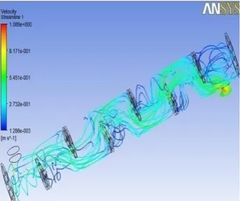
Simulation results are obtained for different angle. It is seen that the temperature gradually increases from 300k at the inlet to 340 k at the outlet of the shell side. The average temperature at the outlet surface is nearly 326.22 k for this model. The pressure drop is less for 2kg/s mass flow rate compared to other two mass flow rates. The maximum velocity is 3.02841 m/s for mass flow rate at the inlet and exit surface and velocity magnitude reduces to zero at the baffle surface. It can be compared that 2 kg/s mass flow gives more heat transfer than other two mass flow rates.
[image:3.595.355.528.171.315.2]From the stream line contour, it is found that recirculation near the baffles induces turbulence eddies which would result in more pressure drop for this model. From the result table it is found that the shell outlet temperature decreases with increasing mass flow rates. Increment in mass flow rate gives also increment in velocity.
Velocity Streamline Contour
Temperature Contour
© 2016, IRJET | Impact Factor value: 4.45 | ISO 9001:2008 Certified Journal
| Page 959
Velocity ContourFig.4:Velocity Streamline ,Temperature, Pressure and Velocity Contour for 0 baffle angle
Velocity Streamline Contour
Temperature Contour
Pressure Contour
Velocity Contour
Fig.5:Velocity Streamline, Temperature, Pressure and Velocity Contour for 20 baffle angle
© 2016, IRJET | Impact Factor value: 4.45 | ISO 9001:2008 Certified Journal
| Page 960
Table-2:
CFD Result
Baffle angle Mass flow
rate[kg/s] Outlet Temperature [K]
Velocity [m/s]
0 2 330.32 0.7551
20 2 331.37 1.51
3. CONCLUSIONS
Shell and tube heat exchanger for shell side study of the fluid flow with zero baffle inclination angle is modeled in the Pro-E Software. The initial CFD analysis have been performed in the ANSYS Software. The k-ԑ turbulence model is used for the simulation based on the literature survey. The initial simulation results agree with the fundamental physics of the
heat transfer in the heat exchanger. The results shows the following points.
CFD has emerged as a cost effective alternative and it provides speedy solution to heat exchanger design and optimization.
The k - ε turbulence model has been most widely employed for heat exchanger design optimization From the CFD analysis it is found that the shell outlet
temperature decreases with increasing mass flow rates. Increment in mass flow rate gives also increment in
velocity.
20º baffle angle give good heat transfer than other angle.