© 2016, IRJET ISO 9001:2008 Certified Journal Page 1064
MUTUAL COUPLING REDUCTION TECHNIQUES IN MICROSTRIP
PATCH ANTENNAS: A SURVEY
Shruti Dhamankar
1, Snehal Lopes
21
Assistant professor, Dept. of Electronics and Telecommunication, St. Francis Institute of Technology, Maharashtra,
India
2
Assistant professor, Dept. of Electronics and Telecommunication, St. Francis Institute of Technology, Maharashtra,
India
---***---
Abstract–An
important
challenge
in
communication industry is to reduce the total
size of devices. Similarly array size reduction has
attracted increasing interest in recent years.
Placing elements of an antenna array close to
each other is certainly one way to reduce the
total size of an array antenna. However, one of
the factor called mutual coupling depends on
inter
element
separation
and
relative
orientation, causes undesirable effects on
antenna characteristics. Therefore, within a
compact structure of an antenna, reduction in
mutual coupling in microstrip antennas is a
major challenge.
Key Words: Electromagnetic bandgap (EBG),
multiple-input multiple-output (MIMO) antennas, mutual coupling, split ring resonator (SRR), Defected Ground Planes (DGS)
1.INTRODUCTION
Surface waves and near fields can lead to coupling between coplanar and patch antennas [1]–[3]. Near field coupling arises when an antenna is placed in the near-field zone of other antenna. This coupling is strong in situations where the antennas are placed on dielectric substrates having low permittivity [3]. In such cases, the coupling can result in degradation to the antenna’s radiation characteristics. Apparently surface waves are weakly excited in very thin grounded dielectric substrates, space-waves dominate as well as produces strong coupling when antennas are in close area. The study of the mutual coupling problem started several decades ago, and several research efforts have been devoted to combat the mutual coupling between coupled antennas to improve antenna radiation characteristics.
2. TECHNIQUES TO REDUCE MUTUAL COUPLING
Mutually coupling among closely spaced radiating elements is essential for the performance of microstrip antenna systems due to fact that induced currents, input impedance and radiation patterns are affected when antenna elements are correlated which in turn reduces capacity of MIMO system [4] and simple solution to reduce correlation is through physically separating radiating elements by distance greater than . However this solution is impractical in hand held wireless devices considering space limitation constraints. There are Methods to reduce mutual coupling between radiating elements in MIMO system and antenna array systems discussed in following sections.
2.1 USING ELECTROMAGNETIC BAND GAP (EBG)
STRUCTURES
Basically Electromagnetic band gap (EBG) structures are realized by periodic arrangement of dielectric materials and shows characteristics of band-pass or bandstop [5] and makes isolation between components [6]. Coupling between the microstrip antenna arrays is the essential problem that always exists. To solve the problem, metamaterial is used in a rectangular patch antenna array substrate in order to reduce coupling between array antennas [7]-[9].
© 2016, IRJET ISO 9001:2008 Certified Journal Page 1065 Fig. 3 Schematic view of proposed array and unit cell of
UC-EBG structure [9]
In paper [10], EBG structure has strong effect in reducing the surface wave in E-plane condition, hence the coupling between antennas will be reduced. On the other hand, for H-plane a state EBG cell does not provide any reduction in mutual coupling. This EBG structures is reducing mutual coupling between patch antenna MIMO arrays. 2×5 EBG structures are used to reduce mutual coupling more than 20 dB. The total size of the antenna is 36mm×68mm×1.6 mm [10].
Fig. 1 Patches array antenna with EBG Structure a) simulation and dimensions b) fabricated antenna [10]
In this paper [11], a mushroom-like EBG structure is implemented in the design of microstrip antenna arrays to reduce the strong mutual coupling caused by the thick and high permittivity substrate without sacrificing the compact size or bandwidth of the antenna elements. The EBG structure is analyzed using the FDTD method. Compared to other approaches such as cavity back structure, the EBG structure demonstrates a better performance to improve the mutual coupling. 8 dB mutual coupling reduction is observed at the resonant frequency. It can be used in various antenna array applications.
Fig. 2 Microstrip antennas separated by the Mushroom-like EBG Structure for a low mutual coupling. Four columns EBG Patches are used [11]
2.2 USING SPLIT RING RESONATOR (SRR)
STRUCTURE
[image:2.595.38.286.414.549.2]© 2016, IRJET ISO 9001:2008 Certified Journal Page 1066 Fig. 4 Top and side views for the two patch antennas with
the SCSRR etched on the ground plane[15]
Capacitively loaded loop (CLL) magnetic resonators are used in order to decorrelate two monopole antennas [16]. Although the coupling had been reduced in [16], the antenna elements were not well-matched. In [17], split-ring resonator (SRR) magnetic inclusions were used to reduce the coupling between closely-spaced monopole antennas. Higher suppression of mutual coupling was achieved in [17] in comparison to [16].
[18] Mutual coupling between closely spaced high profile monopole antennas was investigated with particular focus on multiple-input multiple output (MIMO) systems. A unit cell of the broadside coupled rectangular split-ring resonators (BC-SRR) metamaterial is designed in order to decouple the antenna system while at the same time maintain low correlation between the antenna elements
Fig. 5 Lateral view of two-monopole antennas with SRR inclusions [18]
In paper [19] SSRR is a metamaterial structure which consists of single square shaped ring with gap. This structure is printed on a dielectric substrate of thickness 0.6mm and permittivity 4.4. PSO is used as an optimization tool for design and optimization of the square split ring resonator (SSRR), which exhibits metamaterial characteristics. The optimized SSRR is used for reduction of mutual coupling in microstrip antenna array designed for wireless applications. An array of single ring SSRR is used as a metamaterial structure, which is placed over the antenna array as shown in Fig.6. The position of the SSRR array is changed to study the effects on mutual coupling in the antenna array. It provides comparable reduction in mutual coupling.
a) b) c)
d)
Fig. 6 a) top view of unit cell of the metamaterilal periodic structure b) equivalent inductance of the SRRR c) equivalent circuit of SRRR d) overall structure of an antennas including SRRR [19]
[image:3.595.310.548.298.591.2] [image:3.595.55.263.550.720.2]© 2016, IRJET ISO 9001:2008 Certified Journal Page 1067 the antenna arrays, and widens the stop band. The split
[image:4.595.367.502.192.331.2]spiral shape resonator keeps the antenna having low-profile, lightweight, and the far-field properties are practically unchanged. Also the proposed spiral shape resonator achieves a 23dB reduction in the mutual coupling and interference effects.Because of the opposite signs of the two parameters ε and µ, these structures can block the surface waves inside the substrate of the antenna and guide them in other directions.
Fig. 7 Complementary split spiral Resonator (CSSR) unit cell [20]
Fig. 8 simulation geometry of metamaterials using
Complementary split spiral Resonator (CSSR) unit cell [20]
In [21] MTM are nothing but unit cell of specific shape and material which are periodically arranged at intervals shorter than the specified wavelength. Since MTMs are generally not available in nature and one has to imposed them, they can be classified asi) Single negative MTM (SNG) ii) Double negative MTM (DNG) iii) Electromagnetic Band-gap MTM (EBG) Surface waves and radiated wave are the two causes for increased mutual coupling which affect the antenna performance.Thin Wire (TW), split ring resonator (SRR), omega, mushroom, Fishnet and many more. These structures can be constructed using either
[image:4.595.69.257.235.388.2]metal or any dielectric material. Every homogenous structure results into either into negative ε or negative µ or both. Each structure has its own advantages along with its limitations. TW results into negative ε and positive µ in desired frequency range which is decided by dimensions of TW structure which are described in fig. 9.
Fig. 9 TW Structure [21]
TW structure has negative refractive index and hence it can be used them for enhancement of isolation. An array of such TW structure had been placed between two antenna elements as well as at the radiation edge also and is shown in fig.10.Array of TW at the center helps to reduce mutual coupling due to surface waves. Array of TW at the radiating edge helps to reduce mutual coupling due to near field radiations.
Fig. 10 Technique used for isolation Enhancement [21]
TW structure not only enhances the isolation but also improves the antenna parameters also.
[image:4.595.78.257.443.574.2] [image:4.595.320.537.477.592.2]© 2016, IRJET ISO 9001:2008 Certified Journal Page 1068 metamaterial structure reduced mutual coupling by
suppressing surface waves.
a) b) Fig. 11 a) A unit cell of periodic Structure b) view of array
antenna with SR structure for 3 rows [22]
2.3 USING DEFECTED GROUND PLANES (DGS)
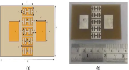
[image:5.595.309.560.348.514.2][23] A low mutual coupling design for two and four elements microstrip antenna array were proposed. A new distribution for dumbbell shaped defect on the ground plane of the antenna is inserted between the patches creating a band gap in the operation frequency band of the antenna. By suppressing the surface waves, it provides a very low mutual coupling between array elements. The DGS antenna was analyzed using a finite integration technique (FIT) and a mutual coupling reduction of 35.6dB was achieved. The analysis indicates that increasing number of dumbbells reduces the mutual coupling between elements. Radiation patterns have minimal change in the broadside direction but back lobe level is increased. However, the gain and the efficiency are decreased due to penetration of DGS in the ground plane.
Fig.12 Five cells Dumbbell shape DGS between two elements array [23]
Number of structures is available for DGS to reduce coupling between microstrip patches.
2.2 USING EBG AND SRR
In paper [24] One-dimensional electromagnetic bandgap (1-D EBG) and split ring resonator (SRR) structures were inserted between two closely located monopole antennas to suppress mutual coupling. The 1-D EBG and SRR structures in these planar multiple antennas function as a reflector and wave trap, respectively. With the effect of these two structures, the mutual coupling between the two antennas is reduced by more than 42 dB and the back lobes are reduced by 6 dB.
The two-port planar antenna with1-D EBG and SRR structure was operated at 2.46 GHz as illustrated in Fig.13. The spacing between the two monopole elements was fixed at 24 mm (0.19λ0) antennas were fed via coaxial
cables. The reference antenna and the antenna with the 1-D EBG structures were fabricated to operate at the same frequency to investigate the effects of the 1-D EBG and SRR structures.
Fig. 13 Configuration of planar multiple antenna with 1-D EBG and SRR structures a) fabricated antenna b) Thin wire
c) Nested SRR structure [24]
Inserting the SRR structure between the two EBG columns, the mutual coupling is additionally suppressed by more than 37.4 dB and the impedance matching property is also improved.
3. CONCLUSION
Survey shows the different techniques to reduce mutual coupling between antenna elements. Ideally it should be
[image:5.595.60.266.554.705.2]© 2016, IRJET ISO 9001:2008 Certified Journal Page 1069 shape slots in radiating patch to increase bandwidth of a
resonant frequency.
REFERENCES
[1] A. Bhattacharyya, “Characteristics of space and surface
waves in a multilayered structure,” IEEE Trans. Antennas Propag., vol. 38, no. 8, pp. 1231–1238, Aug. 1990.
[2] D. Jackson, J. Williams, A. Bhattacharyya, R. Smith, S.
Buchheit, and S. Long, “Microstrip patch designs that do not excite surface waves,” IEEE Trans. Antennas Propag., vol. 41, no. 8, pp. 1026–1037, Aug. 1993.R. Nicole, “Title of paper with only first word capitalized,” J. Name Stand. Abbrev., in press.
[3] M. Nikolic, A. Djordjevic, and A. Nehorai, “Microstrip
antennas with suppressed radiation in horizontal directions and reduced coupling,” IEEE Trans. Antennas Propag., vol. 53, no. 11, pp. 3469–3476, Nov. 2005.
[4] G. J. Foschini and M. J. Gans, On Limits of Wireless
Communications in a Fading Environment when Using Multiple Antennas, Wireless Personal Communications , vol 6, issue 3, pp. 311–335, 1998
[5] Islam, M. T. and M. S. Alam, “Compact EBG structure
for alleviating mutual coupling between patch antenna array elements,” Progress In Electromagnetics Research, vol. 137, 425–438, 2013.
[6] Sharawi, M. S., A. B. Numan, and D. N. Aloi, “Isolation
improvement in a dual-band dual-element MIMO antenna system using capacitively loaded loops,” Progress In Electromagnetics Research, vol. 134, 247– 266, 2013.
[7] Xie, H.-H., Y.-C. Jiao, L.-N. Chen, and F.-S. Zhang, “An
effective analysis method for EBG reducing patch antenna coupling,” Progress In Electromagnetics Research Letters, Vol. 21, 187– 193, 2011.
[8] S. M. Moghadasi, A. R. Attari, and M. M. Mirsalehi,
“Compact and wideband 1-D mushroom-like EBG filters,” Progress In Electromagnetics Research, vol. 83, 323–333, 2008.
[9] H. S. Farahani, M. Veysi, M. Kamyab, and A. Tadjalli,
“Mutual coupling reduction in patch antenna arrays using a UC-EBG superstrate,” Antennas and Wireless Propagation Letters, vol. 9, 57–59, 2010.
[10] M. N. Moghadasi, R. Ahmadian, Z. Mansouri, F. B.
Zarrabi, and M. Rahimi, “Compact EBG Structures for Reduction of Mutual Coupling in Patch Antenna MIMO Arrays,” Progress In Electromagnetics Research, vol. 53, Pp. 145–154, 2014.
[11] F. Yang and Y. R. Samii, “Microstrip Antennas
Integrated With Electromagnetic Band-Gap (EBG) Structures: A Low Mutual Coupling Design for Array Applications” IEEE Trans. on Antennas And Propagation, vol. 51, No. 10, Pp. 2936-2946, Oct 2003.
[12] E. R. Iglesias, O. Q. Teruel, and L. I. Sanchez, “Mutual
coupling reduction in patch antenna arrays by using a planar EBG structure and a multilayer dielectric substrate,” IEEE Trans. Antennas Propag., vol. 56, no. 6, pp. 1648–1655, Jun. 2008.
[13] K. Buell, H. Mosallaei, and K. Sarabandi, “Metamaterial
insulator enabled super directive array,” IEEE Trans.
Antennas Propag., vol.55, no. 4, pp. 1074–1085, Apr. 2007.
[14] J. Garcia, F. Martin, F. Falcone, J. Bonache, J. Baena, I.
Gil, E. Amat, T. Lopetegi, M. Laso, J. Iturmendi, M. Sorolla, and R. Marques, “Microwave filters with improved stopband based on sub-wavelength resonators,” IEEE Trans. Microw. Theory Tech., vol. 53, no. 6, pp. 1997–2006, Jun. 2005.
[15] M. M. Bait-Suwailam, O. F. Siddiqui, and O. M. Ramahi,
“Mutual Coupling Reduction Between Microstrip Patch Antennas Using Slotted-Complementary Split-Ring Resonators”, IEEE Antennas And Wireless Propagation Letters, vol. 9, pp. 876-878, 2010.
[16] P. J. Ferrer, J. M. Gonzalez-Arbesu, and J. Romeu,
“Decorrelation of two closely spaced antennas with a metamaterial AMC surface,” Microw. Opt. Tech. Letts., vol. 50, no. 5, pp. 1414–1417, May 2008.
[17] M. M. Bait-Suwailam, M. S. Boybay, and O.M.Ramahi,
“Mutual coupling reduction in MIMO antennas using artificial magnetic materias,” in Proc. 13th Int. Symp. on Antenna Technology and Applied Electromagnetics (ANTEM/URSI), pp. 1–4, Feb. 2009.
[18] M. M. Bait-Suwailam, M. S. Boybay, and O. M. Ramahi,
“Electromagnetic Coupling Reduction in High-Profile Monopole Antennas Using Single-Negative Magnetic Metamaterials for MIMO Applications”, IEEE Trans. on Antennas And Propagation, vol. 58, no. 9, pp2894-2902, Sept 2010.
[19] B. Choudhury, S. Manickam, and R. M. Jha , “Soft
Computing Techniques for Mutual Coupling Reduction in Metamaterial Antenna Array” , Hindawi Publishing Corporation Journal of Optimization, Article ID252806, 7pages, 2013
[20] B. M. Yousef, A. A. Shaalan, H. Attia, K. H. Awadalla
,“Mutual Coupling Reduction between Microstip Antennas Using complementary Split Spiral Resonators (CSSRS)” , IOSR Journal of Electrical and Electronics Engineering (IOSR-JEEE) , vol 10, Issue 5, PP 38-44, Oct. 2015.
[21] A. A Odhekar G. Arunkumar, D. R. Poddar, “Mutual
Coupling Reduction using Metamaterial Structure for Closely Spaced Microstrip Antennas” International Conference on Communication Technology 2013
[22] H. Kondori, M. A. Mansouri-Birjandi, S.
Tavakoli,“Reducing Mutual Coupling in Microstrip Array Antenna Using Metamaterial Spiral Resonator”, International Journal of Computer Science Issues, vol. 9, Issue 3, No 1,pp- 51-56, May 2012.
[23] M. I. Ahmed, E. A. Abdallah, H. M. Elhennawy, “Design,
Simulation, Fabrication, and Measurement of Antenna Array with Low Mutual Coupling for ISM Band Wireless Applications” International Journal of Advanced Research in Electrical, Electronics and Instrumentation Engineering, vol. 3, Issue 10, Oct. 2014
[24] J. Y. Lee, S. H. Kim, and J. H. Jang, “Reduction of Mutual
![Fig. 6 a) top view of unit cell of the metamaterilal periodic structure b) equivalent inductance of the SRRR c) equivalent circuit of SRRR d) overall structure of an antennas including SRRR [19]](https://thumb-us.123doks.com/thumbv2/123dok_us/8201902.815826/3.595.310.548.298.591/metamaterilal-periodic-structure-equivalent-inductance-equivalent-structure-including.webp)
![Fig. 9 TW Structure [21]](https://thumb-us.123doks.com/thumbv2/123dok_us/8201902.815826/4.595.78.257.443.574/fig-tw-structure.webp)

