International Journal of Emerging Technology and Advanced Engineering
Website: www.ijetae.com (ISSN 2250-2459,ISO 9001:2008 Certified Journal, Volume 5, Issue 8, August 2015)
297
Effect of Working Fluid Loading, Mesh Layer and Orientation on
the Performance of Screen Covered Axial Grooved Heat Pipe
(An experimental approach of heat pipe… a high potential heat exchanger)
V. H. Mutchi. Satish Kumar
1, R. S. Reddy
2, K. V. Sharma
3 1Research Scholar, JNTU, Hyderabad, India
2Senior Deputy General Manager(Retd.), Heat Transfer & Fluid Flow Lab, Corporate R & D, BHEL, Vikas Nagar, Hyderabad,
India.
Present: Professor & Head, (Mech), Mallareddy Engineering College, Hyderabad., India 3
Prof. and Head, Centre for Energy Studies, Dept. of Mechanical Engg., JNTU College of Engineering, Hyderabad, Andhra Pradesh, India
Abstract - An experimental study has been carried out to determine the effect of the amount of working fluid (water) on the performance of the carbon steel–water screen covered axial grooved heat pipe. It was found that the effective thermal resistance decreases with an increase in heat flux and maintained approximately constant value at higher heat fluxes. The heat pipe with amounts of working fluid close to that required to fully saturate the wick performed well. The heat pipe with significantly less working fluid had somewhat lower effective thermal resistances, but the heat transfer rate was decreased.
Keywords- Heat pipe, axial groove, screen, working fluid, effective thermal resistance, heat transfer rate.
I. INTRODUCTION
Heat pipe is device which transfers heat from one point other point or from a heat source to heat sink with least possible temperature drop. The heat pipe can be called as a high potential heat exchanger since it transfers high rates of heat energy with least temperature gradient. The interest in the use of heat pipes for thermal management increases due to increasing heat flux requirements and thermal constraints in many industrial applications. The thermal response of heat pipes is typically characterized by both its maximum heat transport rate and its effective thermal resistance. There are a number of different failure modes that limit the maximum heat transfer rate in heat pipes. In many moderate temperature applications, the heat transport rate is typically limited by the capillary pressure that can be generated by the wick structure. So there has been considerable research focused on developing better models to predict the pressure drop that occurs in heat pipes. This has included so many numerous numerical and analytical investigations in the area of heat pipes.
The concept of heat pipe could be credited separately to RS Gaugler [1] of General Motors Corporation USA and also to G.M.Grover [2] of US Atomic Commission. Since heat pipes are very effective devices for transporting large amount of heat with small temperature gradients, they have been emphasized to cool the various electronic components such as power electronics, electronic chips, thermo electrics, air conditioning, engine cooling and others [3, 4].
Axial groove heat pipe is an important type finding a role in air preheaters, space applications, air craft and boiler applications and cooling the electronic equipment. It ensures low resistance to the liquid flow. For small temperature drops and relatively high axial heat flow rates in conjunction with low conductivity working fluids, the axial groove heat pipes are most suitable. Since it provides high conductance and reliability at a moderate cost, the research is going on this grooved heat pipes.
Since the studies on axial grooved heat pipes, theoretically and experimentally are seldom found in the literature [5, 6, 7], this work is an attempt in this direction and deals with the experimental investigation of the performance of a screen covered axial grooved heat pipe. The analysis of the steady state characteristics is carried out in this work and also the effect of working fluid loading on the performance of the heat pipe.
II. EXPERIMENTAL SETUP
International Journal of Emerging Technology and Advanced Engineering
Website: www.ijetae.com (ISSN 2250-2459,ISO 9001:2008 Certified Journal, Volume 5, Issue 8, August 2015)
298 The pipe is cleaned initially, with the help of evacuating and filling rig, the working fluid is admitted in to the pipe. Heat pipe comprises of 4 sections. The bottom section or one end of the pipe is called evaporator is of length, 300mm to which heat is supplied with the help of heaters and the second section is adiabatic of length 200mm which is externally insulated by glass wool, the third section is condenser of length 400mm from which heat is taken out from the system by the circulation of cooling water flowing through the water jacket provided to the condenser of the heat pipe. The fourth section is non-condensable section of length 100mm for non condensable gases.
[image:2.612.53.254.276.371.2](E=Evaporator, C=Condensor, A=Adiabatic section, N=Non-condensible zone. (All dimensions are in cm)
Figure 1: Schematic Layout of experimental setup.
The experiment is conducted to evaluate the performance of heat pipe in horizontal and vertical, other inclination modes. When the heat is supplied to evaporator section, the same amount of energy is absorbed by the working fluid in the form of latent heat through vaporization process of working fluid and turned to vapor. These vapors moves to the other end of the pipe passing through adiabatic section of heat pipe and enters the condenser section and gives this heat to the cooling water which is continuously flowing through the water jacket and thus condensed. The liquid condensate returns back to the evaporator along the grooves due to capillary pumping head developed in the process when it is operated in horizontal mode. The gravitational forces assist the capillary head to bring the liquid condensate from condenser to evaporator in the case of vertical mode of operation and other inclination modes of operation. The non condensable gases if any, occupies the non-condensable zone of the pipe. Heat pipe can transmit as high as 100 times to that of a standard heat conductor of similar size.
Heat pipe steady state characteristics are studied for different water flow rates at a particular heat input.
Similar type of experiment is carried for the same water flow rates at different heat in puts. In the same manner the experiments are done for horizontal and vertical modes and also for other inclination modes of operation.
In the second stage of experimentation, the heat pipe is tested with 100 %, 90%, 80% working fluid (water) loading for different heat inputs at 100W, 200W, 300W, 400W, 500W under the condenser cooling water flow rates of 1 lpm, 1.25 lpm, 1.50 lpm respectively.
III. RESULTS AND DISCUSSIONS
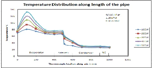
The temperature distribution along the wall of the heat pipe with 100% working fluid loading, when operated in horizontal position for heat inputs of 100W, 200W, 300W, 400W and 500W at a water flow rate of 1.25 lpm is shown in Fig.2. It is observed that the temperature is fairly uniform over the condenser wall and it varies appreciably along the evaporator length with the maximum occurring at the middle of the evaporator section. It is because the heat transfers through end cap of heat pipe to the surrounding atmosphere at one end and through the condenser on the other end of the evaporator section. These two are responsible to maintain the lower temperatures on either side of the evaporator section of heat pipe.
Figure 2: Temperature distribution along axis (Horizontal Position).
[image:2.612.323.572.420.531.2]International Journal of Emerging Technology and Advanced Engineering
Website: www.ijetae.com (ISSN 2250-2459,ISO 9001:2008 Certified Journal, Volume 5, Issue 8, August 2015)
[image:3.612.319.580.122.273.2]299
Figure 3: Temperature distribution along axis (Vertical Position).
This maximum temperature recorded in horizontal mode of operation is due to the fact that insufficient quantity of working fluid available in the evaporator section because the condensate flow is caused by capillary forces only. The minimum temperature is recorded in vertical mode of operation, since the condensate flow is assisted by gravity forces. So the heat pipe can take more heat load in vertical mode (keeping the evaporator section at bottom of the pipe) of operation compared to the heat pipe operated in horizontal position.
IV. EFFECT OF FLUID LOADING
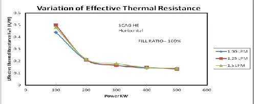
The effective thermal resistances for the heat pipe with 100% working fluid loading for different heat inputs 100W, 200W, 300W, 400W, 500W under condenser cooling water flow rates of 1 lpm, 1.25 lpm, 1.50 lpm respectively have been calculated for the horizontal and vertical modes of heat pipe operations.
Figure 4: Variation of effective Thermal resistance with power inputs under different condenser cooling water flow rates (Horizontal
[image:3.612.48.293.128.267.2]Position).
Figure 5: Variation of effective Thermal resistance with power inputs under different condenser cooling water flow rates (Vertical Position).
The above fig. 4 & 5 shows the variation of effective thermal resistance with different heat inputs 100W, 200W, 300W, 400W, 500W with 100% working fluid loading at different condenser water cooling flow rates of 1 lpm, 1.25 lpm, 1.5 lpm respectively. It is observed that the effective thermal resistance decreases from lower heat inputs to higher heat inputs.
Figure 6: Variation of effective Thermal resistance with different condenser cooling water flow rates (1 lpm, 1.25 lpm, 1.5 lpm) at 200w
(Horizontal Position vs Vertical Position).
[image:3.612.327.564.390.491.2] [image:3.612.48.297.507.609.2]International Journal of Emerging Technology and Advanced Engineering
Website: www.ijetae.com (ISSN 2250-2459,ISO 9001:2008 Certified Journal, Volume 5, Issue 8, August 2015)
[image:4.612.46.301.99.393.2]300
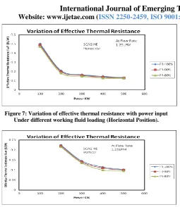
Figure 7: Variation of effective thermal resistance with power input Under different working fluid loading (Horizontal Position).
Figure 8: Variation of effective thermal resistance with power input Under different working fluid loading (Vertical Position).
The above fig. 7 & 8 shows the variation of effective thermal resistance with different heat inputs 100W, 200W, 300W, 400W, 500W with 100%, 90%, 80% working fluid loadings at condenser water cooling flow rate of 1.25 lpm when heat pipe is operated in horizontal and vertical mode respectively. It is observed that the effective thermal resistance of heat pipe is increased when the working fluid charge was increased. It is also observed that the effective thermal resistance is more with working fluid loading is almost saturated level i.e., nearer to 100%.
[image:4.612.48.301.127.249.2]For the lower FR 80% the thermal resistance was lower but this had significantly lowers the maximum heat transfer. Since the working fluid did not completely saturated the wick. If the working fluid FR is more than 100%, had a higher thermal resistance but in this case the excess liquid must pool in the heat pipe and affects the evaporation and condensation processes.
Figure 9: Effect of orientation on the heat transfer rate (a comparison Horizontal Vs Vertical)
[image:4.612.324.581.132.273.2]The fig. 9 shows the effect of the orientation on the heat transfer rate of the heat pipe. The comparison curve between vertical and horizontal modes of operation at fill ratio 100% shows that the heat pipe under vertical mode of operation performs well and transferring more amount of heat energy when compare with horizontal mode. It is because in vertical mode, the gravitational forces assists the capillary forces.
Figure 10: Effect of mesh layer on the heat transfer rate (A comparison AGHE Vs SCAGHE)
[image:4.612.323.582.400.575.2]International Journal of Emerging Technology and Advanced Engineering
Website: www.ijetae.com (ISSN 2250-2459,ISO 9001:2008 Certified Journal, Volume 5, Issue 8, August 2015)
301 The figure shows a comparison between AGHE (with zero layer mesh) and SCAGHE (with one layer mesh) at vertical position with 1.25 lpm of condenser cooling water flow rate. From this fig 10, it is seen that the performance of SCAGHE is more than AGHE.
V. CONCLUSION
The performance of a screen covered axial grooved heat pipe is evaluated for the same working fluid (water) at horizontal and vertical modes, other inclination modes of operation. Since the gravitational forces are acted beside the pumping head, the performance of vertical mode heat pipe is better than horizontal mode heat pipe when operating between the same conditions of parameters.
Acknowledgement
The first author is working as Associate Professor in the department of mechanical engineering of PVPSIT and grateful to the management of Prasad .V. Potluri Siddhartha Institute of Technology, Vijayawada for their encouragement and the author is very much thankful to the higher authority and executives of BHEL Corporate (R&D) Hyderabad for permitted to carry out the design, fabrication and experimental works in their organization.
REFERENCES
[1] Gaugler, R.S. Heat transfer Device. US Patent 2350348 (1942).
[2] Grover, G.M. Evaporation and Condensation heat transfer device. US Patent 3229759, (1963).
[3] Eastman, G.Y. The Heat Pipe, Scient, American, 218 (5), P.P. 38-46, (1968).
[4] Feldman, K.T. and Whiting, G.H. Applications of the heat pipe, Mech. Engg., 90, PP. 48-53, (US), (1968).
[5] Kamotani Y. Analysis of Axially grooved heat pipe condensers. AIAA Paper, 1976, N. 76-147.
[6] Rifert V.J., Barabash P.A. Industrial thermal technique, 1980. V.2, N5.P. 39-43.
[7] Khrustalev D.K. Heat transfer in condenser of low temperature heat pipe with axial grooves. Processes of power and mass transfer in pore medium with phase transformation. Minsk., Academy of Sciences, USSR, 1982. P. 32-45.
[8] Polasek F., Stulc P., Sasin V. Analysis of thermal and fluid characteristics of heat pipes with axial grooves, 5th International Heat
Pipe Conference. Tchukuba, Japan, 1984.
[9] Terpestra, M. and Vanveen, J., 1987, “Heat Pipes: Construction application a study of patents and patent applications”, Elsevier Applied Science, New York.
[10] Vasilyev L.L., Grokovich L.P., Khrustolev D.K. Thermal Pipes in systems with renewal power sources, Minsk, Science and Technology, 1988, P. 36 – 58.
[11] Faghri, A. Dogineni, S. and Cao, Y., 1995, “Heat Transfer – Part A”, 28, PP. 723-737.
[12] P.D. Dunn, D.A. Reay, Heat Pipes, second ed., pergamon press Oxford, England, 1978.