International Journal of Emerging Technology and Advanced Engineering
Website: www.ijetae.com (ISSN 2250-2459, ISO 9001:2008 Certified Journal, Volume 5, Issue 2, February 2015)
210
Fuzzy Logic Applications on Induction Motor for Axis Control
S. Sankar
1, V. Deepalakshmi
2, L. Jayaprakash
31Professor of EEE, Panimalar Institute of Tech, Chennai, India 2,3Assistant Professor of EEE, Panimalar Institute of Tech, Chennai, India
Abstract-- This paper presents a fuzzy logic controller for an induction motor. The fuzzy logic controller is used for to control the different parameters of motor. This system are used in a combined way, they are called Neuro-Fuzzy Systems. This term, however, is often used to assign a specific type of system that integrates both techniques. This type of system is characterised by a fuzzy system where fuzzy sets and fuzzy rules are adjusted using input output patterns. The efficient optimization control based on an on-line search of optimum flux is done using fuzzy logic controller. The fuzzy control has the advantages of being able to handle noisy and inaccurate input signals, and the step size of the decrement in adaptive, so that fast convergence in the control is attained.
Keywords-- fuzzy rules, Induction motor, Concurrent Systems, Neuro-Fuzzy Architectures, Non-Linear Modelling.
I. INTRODUCTION
Industry automation is mainly developed around motion control systems in which controlled electric motors play as a heart of the system a crucial role. The high performance motor control systems thus, contribute to a great extent, to the desirable performance of automated manufacturing sector by enhancing the production rate and the quality of products. In fact the performance of modern automated systems, defined in terms of swiftness, accuracy, smoothness and efficiency, mainly depends on the motor control strategies [1]. The advancement of control theories, power electronics and microelectronics in connection with new motor designs and materials has contributed largely to the field of electric motor control for high performance systems.
Many schemes have been proposed for the control of induction motor drives, among which the field oriented control [2-3], or vector control, has been accepted as one of the most effective methods. The vector control strategy is formulated in such a way that the stator current phasor, in the two-axis synchronously rotating reference frame, has two components: magnetizing current component and torque-producing current component.
II. MODELING OF INDUCTION MOTOR
The model of induction motor without damper winding has been developed on rotor reference frame using the following equations.
Vq = Rs iq + ωr λd + ρ λq (1)
Vd = Rs id – ωr λq + ρ λd (2)
Flux Linkages are given by
λq = Lq iq (3)
λd = Ld id + λf (4)
Substituting equations 3 and 4 into 1 and 2
Vq = Rs iq + ωr (Ld id + λf) + ρ Lq iq (5)
Vd = Rs id – ωr Lq iq + ρ (Ld id + λf) (6)
Arranging equations 5 and 6 in matrix form
[ ] [ ] [ ] (7)
The developed torque [16] to [18] motor is being given by
Te = 3/2 (P/2) (λd iq – λq id) (8)
The mechanical Torque equation is
Te = TL + B ωm + J ω
(9)
Solving for the rotor mechanical speed form equation 9
(∫ ) (10)
and
ωm = ωr
(
)
(11)In the above equations ωr is the rotor electrical speed where as ωm is the rotor mechanical speed.
In FLC scheme the output of the FLC is used as the input of the controlled voltage source which converts the input signal into an equivalent voltage in order to regulate the motor speed.
The proportional plus integral (PI) controller is one of the famous controllers used in a wide range in the industrial applications. The output of the PI controller in time domain is defined by the following equation:
International Journal of Emerging Technology and Advanced Engineering
Website: www.ijetae.com (ISSN 2250-2459, ISO 9001:2008 Certified Journal, Volume 5, Issue 2, February 2015)
211 Where v
[image:2.612.339.543.118.550.2]c(t) is the output of the PI controller, kp is the proportional gain, ki is the integral gain, and e(t) is the instantaneous error signal. The main advantage of adding the integral part to the proportional controller is to eliminate the steady state error in the controller variable. However, the integral controller has the serious drawback of getting saturated after a while if the error does not change its direction.
Fig. 1. The dynamic response of the drive system using a PI controller
[image:2.612.66.270.238.364.2]This phenomenon can be avoided by introducing a limiter to the integral part of the controller before adding its output to the output of the proportional controller [4]. The input to the PI is the speed error (e), while the output of the PI is used as the input of controlled voltage source inverter. And finally the controlled voltage obtained from inverter is fed to the motor for controlling its speed. The dynamic response of the IM driven by the PI controller is shown in Fig. 1.
All membership functions are iteratively adjusted and the result of the FLC corresponds to the minimum training error. The resultant MAMDANI-type FIS has only 21 rules which was found to provide sufficient accuracy after optimization. The membership functions of the inputs are shown in Fig. 2, Fig. 3 and Fig. 4. The reference speed of the motor is set at 700 rad/sec. As soon as the speed reaches the reference speed the PID speed controller forces the speed to remain steady at reference speed. During starting period torque climbs to maximum capability of the motor after that it settles down to steady state value of 3 N-M. Also the current rises to its maximum value and after that comes back to nearly 2 A.
Fig. 2. Error (E)
Fig. 3. Change In Error (CE)
Fig. 4. Output (O)
[image:2.612.343.545.584.697.2]The dynamic response of the PMSM driven by the Fuzzy Logic Controller is shown in Fig. 5.
International Journal of Emerging Technology and Advanced Engineering
Website: www.ijetae.com (ISSN 2250-2459, ISO 9001:2008 Certified Journal, Volume 5, Issue 2, February 2015)
212 The torque, proportional to iqs (with constant flux), can be bipolar. It is negative with negative iqs, and correspondingly, the phase position of iqs becomes negative as shown in Fig.7. An additional torque control loop can be added within the speed loop is as shown in the Fig.6. It can be extended to field-weakening mode by programming the flux command as a function of speed so that the inverter remains in PWM mode. Fuzzy logic based efficiency optimizer can be incorporated with vector controller block, to give maximum developed torque per ampere and optimum transient response [5].
[image:3.612.335.549.118.299.2]III. AXIS CONTROL OF INDUCTION MOTOR
Fig. 6. Direct Vector control block diagram with rotor flux orientation
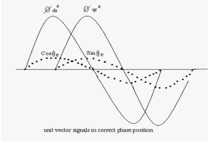
The correct alignment of current ids in the direction of flux ψr and the current iqs perpendicular to it are crucial in vector control. This alignment, with the help of stationary frame rotor flux vectors ψdr
s and ψqr
s
, is explained in Fig.8.
cosθ = ψdrs / ψr (13)
sinθ = ψqrs / ψr (14)
ψr = √ (ψdrs2 + ψqrs2 ) (15)
[image:3.612.65.274.284.434.2]Signals cosθ and sinθ have been plotted in correct phase position as shown in Fig.8. These unit vector signals, when used for vector rotation in Fig.6, give a ride of current ids on the de-axis (direction of ψr) and current iqs on the qe-axis as shown. At this condition, ψqr=0 and ψdr=ψr, as indicated and the corresponding torque expression is given by equation [6].
Fig. 7. Phases showing correct rotor flux orientation
When the iqs polarity is reversed by the speed loop, the iqs position in Fig.7 also reverses, giving negative torque [7]. The generation of a unit vector signal from feedback flux vectors gives the name “direct vector control”.
Fig. 8. Unit Vector signal in correct phase position
[image:3.612.340.546.367.509.2]International Journal of Emerging Technology and Advanced Engineering
Website: www.ijetae.com (ISSN 2250-2459, ISO 9001:2008 Certified Journal, Volume 5, Issue 2, February 2015)
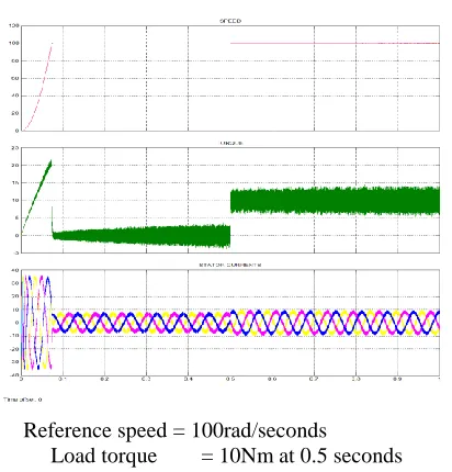
213 Reference speed = 100rad/seconds
[image:4.612.341.547.132.347.2]Load torque = 10Nm at o.5 seconds
Fig. 9.Output of Vector controlled Induction motor drive during starting condition
[image:4.612.65.274.132.369.2]Reference speed = 100rad/seconds Load torque = 0Nm
Fig.10. Output of Vector controlled Induction motor drive during steady state condition
Reference speed = 100rad/seconds
Load torque = 10Nm at 0.5 seconds
Fig. 11.Output of Vector controlled Induction motor drive at 10Nm load
The IM starts in closed-loop because speed and current control are in cascade. The load torque applied to the machine's shaft is set to its nominal value. Two control loops are used: the inner loop regulates the motor's stator currents and the outer loop controls the motor's speed. Using a PWM inverter, a noise is observed in the electromagnetic torque waveform. However, the motor's inertia prevents this noise from appearing in the motor's speed waveform (Fig. 7). The stator currents are quite "noisy," which is to be expected when using PWM inverters. The rotor speed increases fast to its synchronous value after few oscillations and preserves its value (Fig. 7). The current takes initially a high value in order to develop the kinetic energy to accelerate the rotor. After a certain delay the current stabilizes to their nominal value. The reference speed of the motor is set at 700 rad/sec. As soon as the speed reaches the reference speed the PI speed controller forces the speed to remain steady at reference speed. During starting period torque climbs to maximum capability of the motor after that it settles down to steady state value of 3 N-M. Also the current rises to its maximum value and after that comes back to nearly 2 A.
[image:4.612.66.273.384.628.2]International Journal of Emerging Technology and Advanced Engineering
Website: www.ijetae.com (ISSN 2250-2459, ISO 9001:2008 Certified Journal, Volume 5, Issue 2, February 2015)
214 Simulink has been chosen from several simulation tools because of its flexibility in working with analog and digital devices. Mathematical models can be easily incorporated in the simulation and the presence of numerous tool boxes and support guides simplify the simulation of large system as compared to other simulation tools. Simulink is capable of showing real time results with reduced simulation time and debugging.
In the present simulation measurement of currents and voltages in each part of the system is possible, thus permitting the calculation of instantaneous or average losses, efficiency of the drive system and total harmonic distortion. Usually in such a drive system the inverter is driven either by hysteresis or by PWM current controllers. Neural networks and fuzzy systems can be combined to join its advantages and to cure its individual illness. Neural networks introduce its computational characteristics of learning in the fuzzy systems and receive from them the interpretation and clarity of systems representation. Thus, the disadvantages of the fuzzy systems are compensated by the capacities of the neural networks. These techniques are complementary, which justifies its use together.
In a cooperative system the neural networks are only used in an initial phase is as shown in the Fig.12. In this case, the neural network determines sub-blocks of the fuzzy system using training data, after this, the neural networks are removed and only the fuzzy system is executed. In the cooperative neuro-fuzzy systems, the structure is not total interpretable what can be considered a disadvantage.
[image:5.612.338.551.143.205.2]FUZZY SYSTEM NEURAL NETWORK FUZZY SETS FUZZY RULES
Fig.12. Cooperative Systems
A concurrent system is not a neuro-fuzzy system in the strict sense, because the neural network works together with the fuzzy system. This means that the inputs enters in the fuzzy system, are pre-processed and then the neural network processes the outputs of the concurrent system or in the reverse way. In the concurrent neuro-fuzzy systems, the results are not completely interpretable, what can be considered a disadvantage. The structure of concurrent system is as shown in the Fig.13.
[image:5.612.350.537.370.474.2]FUZZY SYSTEM NEURAL NETWORK NEURAL NETWORK FUZZY SYSTEM
Fig.13. Concurrent Systems
A neuro-fuzzy system can be interpreted as a set of fuzzy rules. This system can be total created from input output data or initialised with the à priori knowledge in the same way of fuzzy rules. The resultant system by fusing fuzzy systems and neural networks has as advantages of learning through patterns and the easy interpretation of its functionality. There are several different ways to develop hybrid neuro-fuzzy systems; therefore, being a recent research subject, each researcher has defined its own particular models. These models are similar in its essence, but they present basic differences.
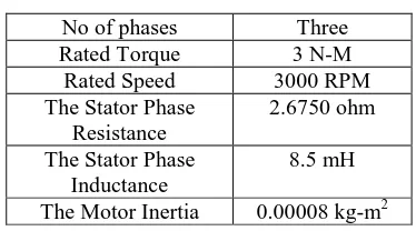
Table 1.
Induction Motor Specifications
No of phases Three
Rated Torque 3 N-M
Rated Speed 3000 RPM
The Stator Phase Resistance
2.6750 ohm
The Stator Phase Inductance
8.5 mH
The Motor Inertia 0.00008 kg-m2
Based on the given data the secondary heat sink and pump were chosen. Pump performance, in the case of 4 in series connected primary heat sinks, is 2.4l/min. Secondary heat sink at such water flow, water temperature of 60C0 and ambient temperature of 25C0 can dissipate 500W.
IV. CONCLUSION
[image:5.612.50.269.475.577.2]International Journal of Emerging Technology and Advanced Engineering
Website: www.ijetae.com (ISSN 2250-2459, ISO 9001:2008 Certified Journal, Volume 5, Issue 2, February 2015)
215 For current controller, PWM is examined and for speed controller, performance of neurofuzzy controllers are examined the simulated results confirmed the viability of the model used in this work and it has been shown that the model is suitable for transient as well as steady state condition. These results also confirmed that the transient torque and current never exceed the maximum permissible value.
REFERENCES
[1] Sollani.J, Esmaily.G: Dynamic performance of the self controlled synchronous motor drive system supplied by SPWM voltage source inverters. ICEE, Teltran, May 2009, pp.311-318. [2] Esmaily.G, Khodabkhshian.A, .Jamshidi.K Vector
controlinduction motors using UPWM voltage source inv erter.IE EE Trans.on Power systems.vol.42, issue 4, Aug 2010, pp.344-350.
[3] Kazmierkowski,MP; A.B.Kasprowicz: Improved direct torque and flux vector control of PWM inverter-fed induction motor drives.IEEE Trans.on indust.Electronis. vol.42, issue 4, Aug 2010, pp.344-350.
[4] Grotstollen,H.;Wiesing,J:Torque capability and control of a saturated induction motor over a wide range of flux weakening” Industrial Electronics,IEEE Transaction on Volu me 42, Issue 4, Aug 2011, pp:374-381.
[5] Soong,W.L.;Miller,T.J.E: Field weakening performance of brushless synchronous ACmotordrives. Electric Power Applications, IEE Proc eedings Volume 141, Issue 6, Nov 2011 Page(s):331 – 340. [6] Sang-HoonKim;Seung-KiSul:Voltage control strategy for maximum
torque operation of an induction machine in the field weakening reg ion Industrial Electronics, IEEE Transactions on Volume 44, Issue 4, Aug 2010 .Page(s):512 – 518.