Design, implementation and modelling of
the single and multiple extensor pneumatic
muscle actuators
AlIbadi, Alaa, NeftiMeziani, S and Davis, ST
http://dx.doi.org/10.1080/21642583.2018.1451787
Title
Design, implementation and modelling of the single and multiple extensor
pneumatic muscle actuators
Authors
AlIbadi, Alaa, NeftiMeziani, S and Davis, ST
Type
Article
URL
This version is available at: http://usir.salford.ac.uk/id/eprint/46304/
Published Date
2018
USIR is a digital collection of the research output of the University of Salford. Where copyright
permits, full text material held in the repository is made freely available online and can be read,
downloaded and copied for noncommercial private study or research purposes. Please check the
manuscript for any further copyright restrictions.
Full Terms & Conditions of access and use can be found at
http://www.tandfonline.com/action/journalInformation?journalCode=tssc20
Systems Science & Control Engineering
An Open Access Journal
ISSN: (Print) 2164-2583 (Online) Journal homepage: http://www.tandfonline.com/loi/tssc20
Design, implementation and modelling of the
single and multiple extensor pneumatic muscle
actuators
Alaa Al-Ibadi, Samia Nefti-Meziani & Steve Davis
To cite this article: Alaa Al-Ibadi, Samia Nefti-Meziani & Steve Davis (2018) Design,
implementation and modelling of the single and multiple extensor pneumatic muscle actuators, Systems Science & Control Engineering, 6:1, 80-89, DOI: 10.1080/21642583.2018.1451787 To link to this article: https://doi.org/10.1080/21642583.2018.1451787
© 2018 The Author(s). Published by Informa UK Limited, trading as Taylor & Francis Group
Published online: 20 Mar 2018.
Submit your article to this journal
View related articles
SYSTEMS SCIENCE & CONTROL ENGINEERING: AN OPEN ACCESS JOURNAL, 2018 VOL. 6, NO. 1, 80–89
https://doi.org/10.1080/21642583.2018.1451787
Design, implementation and modelling of the single and multiple extensor
pneumatic muscle actuators
Alaa Al-Ibadi a,b, Samia Nefti-Mezianiaand Steve Davisa
aComputing, Science and Engineering, University of Salford, Manchester, UK;bComputer Engineering Department, University of Basrah, Basrah,
Iraq
ABSTRACT
The soft actuator represents a valuable addition to the robotics research area in last two decades. These actuators provide significant features such as lightweight, softness, high force to weight ratio and the ability to form in different shapes. This article presents a new length model to the single extensor pneumatic muscle actuator (PMA) which is depended on the constructed parameters and the air pressure. On the other hand, the tensile force formula of the contractor actuator has been modified to describe the extension force of the extensor PMA. The parallel structure of four extensor actuators is designed and implemented as continuum arm. The bending behaviour of the proposed arm is illustrated and modelled mathematically. The length model of the single extensor actuator has validated by the comparison between the model and the experiment data and then a neural network (NN) control system is applied to control the elongation of the extensor PMA. The kinematics for the proposed continuum arm are presented to describe the bending of the arm and its direction.
ARTICLE HISTORY Received 4 January 2018 Accepted 9 March 2018
KEYWORDS
Extensor pneumatic muscle actuator; extension force; extensor continuum arm; kinematics; neural network controller
1. Introduction
Soft actuators have grown commonly reputation among researchers, mainly in the last two decades. As a result, soft robotics has been extensive use in the numerous areas. Researchers from different fields such as mate-rial science, biology and computer and control engi-neering interest in such type of robots (Margheri & Trimmer,2014). This developing research field emphases on robots made of soft materials which increase the safety of human-robot interaction, and make the robot more compliance to its environment (Mutlu, Yildiz, Alici, Marc in het Panhuis, & Spinks,2016; Pillsbury, Guan, & Wereley,
2016). The infinite number of freedom (DOF) is achiev-able by soft robots due to the bending capability of the soft actuator and as a result, a robot end effector can reach every point in the 3D workspace (Trivedi, Rahn, Kier, & Walker,2008). Soft robots have a further positive over rigid robots, where they produce slight resistance to obstacles and can adapt to them. Consequently, soft and fragile payloads could be handled without causing any damages (Jones & Walker,2006).
A pneumatic muscle actuator (PMA) which is built from an inner rubber tube bounded by a braided sleeve (Chou & Hannaford,1996) has been used to create soft robots. The construction of the PMA defines the type of actua-tor, by selecting the length of both the inner tube and
CONTACT Alaa Al-Ibadi [email protected]; [email protected]
the braided sleeve the PMA act as a contraction actua-tor if the braided angle is less than 54.7° (Al-Ibadi, Nefti-Meziani, & Davis,2016; Godage, Branson, Guglielmino, & Caldwell,2012), and the extension actuator if the angle is more than 54.7° (Al-Ibadi, Nefti-Meziani, & Davis,2017b). Moreover, the PMA will produce a tensile force for con-tractor type and an extension force for the extensor PMA.
Important researches have been done to define the contraction force of the pneumatic muscle actuators. Among these researches, the Chou and Hannaford model (Chou & Hannaford,1996) and Tondu and Lopez (2000) is commonly referred. Several modifications and new mod-els are presented to these formulas in order to reduce the error and to consider all the actuator parameters. Davis and Caldwell (2006) study the impact of the braided sleeve on the tensile force. Al-Ibadi, Nefti-Meziani, and Davis (2017a) formulate a model of the contraction force by considering the specifications of the inner rubber tube and the actuator dimensions.
Hannan and Walker (2003) designed a rigid mate-rial continuum robot arm inspired by an elephant trunk, which has the ability to bend in constant curvature by tendons. Bailly and Amirat (2005) implemented and con-trolled two sections continuum robot for surgical applica-tion to enhance the bending behaviour.
© 2018 The Author(s). Published by Informa UK Limited, trading as Taylor & Francis Group.
Several soft prototypes have been designed to achieve a unique application such as OctArm by McMahan et al. (2006) which is flexible, elastic and has good strength, but is complex to build and control because of the mul-tiple pressurized central members that make the design mechanically challenging. The Air-Octor continuum arm by McMahan, Jones, and Walker (2005) on the other hand, is much less complex to build and control because of the single central member and the use of cables as actuators but lacks flexibility and strength due to high cable friction which cannot be overcome by low pressure in the central member, resulting in cable binding which in turn causes undesirable movements of the trunk.
Another design has been implemented by Neppalli and Jones (2007) by using single extensor pneumatic actuator and three cables to arrange the direction of the free end. This design provides bending in an arc of con-stant curvature and it is easy to control by motors, and it can work with an air pressure up to 483 kPa. However, they do not provide any data about the load condition and the grasping performance for the presented soft arm. Several types of controller systems have been used to control the single contraction pneumatics actuator. Ahn and Nguyen (2007) designed a PID controller to control the length of the contractor actuator for three differ-ent loads (0, 5 and 10 kg). Andrikopoulos, Nikolakopou-los, and Manesis (2014) proposed an advanced nonlinear PID (AN-PID) controller by adding nonlinear elements to the conventional PID to enhance the control system due to the high nonlinearity of the PMA performances. Fan, Zhong, Zhao, and Zhu (2015) presented a nonlinear PID controller tuned by a back propagation neural network (BP-NN).
In this article, different lengths of the extensor PMAs have been constructed to study their performances. A novel model of the elongation is presented and vali-dated by comparing the model result with the experi-mental data and a NN control system is applied to control the length of the actuator. The force formula by Tondu and Lopez (2000) of the contraction PMA is modified to describe the extension force. A novel continuum exten-sor arm of four actuators has been proposed. The four actuators are laid in parallel to provide an elongation per-formances along Z-axis and a bending behaviour by acti-vate single or multiple actuators. The bending behaviour of the proposed soft arm has been illustrated and formu-lated as a function of air pressure and the attached load and. Then, the kinematics for this feature are presented.
[image:4.610.319.544.55.130.2]The design of single extensor pneumatic muscle actua-tor is explained in section two of this article. Section three illustrates the elongation performances and the mathe-matical model of the extensor PMA due to the variations in air pressure for three different length actuators. A NN
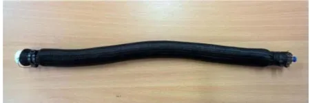
Figure 1.The photograph of the 30 cm extensor PMA.
Figure 2.The basic structure of the pneumatic muscle actuator.
control system is explain in section four to control the actuator length and validate the elongation formula. The load effect on the actuator length is illustrated in section five. In section six, a continuum arm of four extensor actu-ators is designed and its bending behaviour is illustrated. While the kinematics for the bending performances is giving in section eight.
2. The extensor PMA
The construction of the PMA defines its action as a con-traction or extension actuator by controlling the braided angle (θ); as identified in the force formula below, the force either contraction or extension depends on (θ). A photograph of a 30 cm extensor PMA is shown in Figure1. Generally, the PMA is constructed from an inner rubber tube which is covered by a braided sleeve with two solid material terminals which are fixed strongly to ensure that no air leakage occurs. One of the terminals has a small inlet for the actuated air. Figure2shows a basic diagram of PMA with ‘L’ length, ‘D’ diameter and ‘θ’ angle between the vertical axis and braided strand (b).
When the length of the braided sleeve is more than the length of the rubber inner tube in sufficient amount in which the braided angle (θ) is more than 54.7° (Liu & Rahn,
2003), the actuator behaviour is an extensor PMA. In this project, the braided sleeve length is 2.8 times of the inner tube. The percentage of extension differs from one mus-cle to another, and it is up to 50% (McMahan et al.,2006).
3. The elongation model of the single extensor actuator
[image:4.610.325.534.160.262.2]82 A. AL-IBADI ET AL.
Table 1.The initial specifications of the extensor PMAs.
L0(m)
Rubber thickness (m)
Braided thickness (m)
Inner diameter (m)
Rubber stiffness(N/m)
0.2 1.1×10⁻³ 0.5×10⁻³ 12×10−3 363.33
0.3 1.1×10⁻³ 0.5×10⁻³ 12×10−3 363.33
[image:5.610.61.296.64.278.2]0.4 1.1×10⁻³ 0.5×10⁻³ 12×10−3 363.33
Figure 3.The elongation andt.
(L0) are designed and built. Actuators of (20, 30 & 40 cm)
are chosen to cover a range of muscle lengths; all these Muscles have the same initial diameter of (3.3 cm) and an initial braided angle of (71.5°). The material specifications of the constructed actuators are specified in Table1.
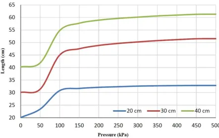
The experiment is done by applying an air pressure via (3/3 matrix solenoid valve) for steps start from 0–500 kPa. And an ultrasound HC-SR04 sensor has been attached to the end of the actuator to calculate the change in the length. An Arduino mega 2650 is used to control the experimental process. The experiment is repeated sev-eral times to each actuator and the length of each PMA is recorded during the elongation (increasing the applied pressure) and the contracting (decreasing the applied air pressure). The results as a function of air pressure are shown in Figure3.
Figure4illustrates the average length of each actua-tor, which represents the average between the elonga-tion and the contracelonga-tion. The sigmoidal shape of muscle length leads to modelling the length of PMA performance as a mathematical sigmoid function.
The average length of each actuator is presented as a sigmoid function individually, then, the three equa-tions combined in one new formula depends on both the air pressure and the initial length as in (1) and (2). The parameters of (2) have been found by curve fitting the parameters of the sigmoidal function of different actua-tors lengths.
L=a− b
1+p
c
d +0.0009L0p
[image:5.610.316.552.230.352.2]2, (1)
Figure 4.The average length of the extensor PMAs.
where
⎡ ⎢ ⎢ ⎣ a b c d
⎤ ⎥ ⎥ ⎦=
⎡ ⎢ ⎢ ⎣
0.2281 0.084598 −0.0013189
−0.94047 0.095934 −0.0014863 0.014934 0.0012083 −0.000026277 0.2080174 −0.0032043 0.0000106189
⎤ ⎥ ⎥ ⎦
× ⎡ ⎣LL020
L30 ⎤
⎦. (2)
The extension ratio for the extensor PMA can be defined as in (3):
ε= L−L0
L0
. (3)
Figure5shows the average length of the PMAs for both the experimental and the model data, and it is clear that there is a significant matching between the two plots for different sets of data.
To validate this formula another actuator has been constructed for the same specifications but with 25 cm initial length.
Figure6illustrates both the experimental and model length characteristics for the new muscle, which it proved the validity of the extensor length formula in (1) and (2).
[image:5.610.323.545.546.701.2]Figure 6.The validation data for the 25 cm extensor actuator.
4. Controlling the actuator length
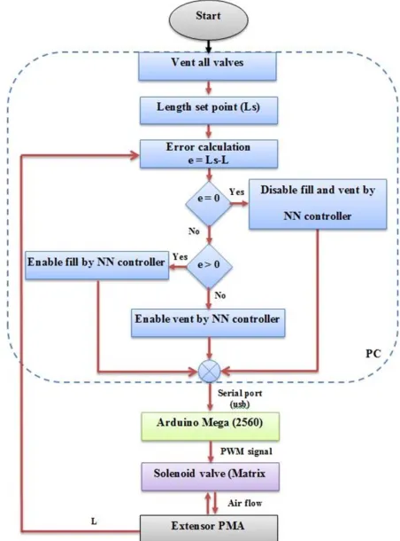
A neural network (NN) controller is designed by Matlab to control the length of single extensor PMA by con-trolling the air filling and venting of the actuator via a 3/3 solenoid (Matrix) valve and an Arduino Mega 2560. Figure7shows the flowchart of the control system and the extensor actuator, the attached load and the ultra-sound sensor are illustrated in Figure8. The NARMA-L2 NN-controller is used of 9-neurons in one hidden layer, 3-delayed plant inputs, 2-3-delayed plants outputs and it is trained by (trainlm) for 100 Epochs. The mean square error (MSE) for the training, testing and validating data is about 10−7. The controller output is the pulse width modula-tion (PWM) signal which controls the air flow for both the filling and the venting processes to achieve the desired length.
An approximate model has been used to train the neu-ral controller and the actuator length as a function of the duty cycle of the controlled input is given by (4).
L=L0+
0.5L0×u
98 , (4) whereLis the actuator length anduis the controlled duty cycle of the pulse width modulation (PWM) signal.L0
rep-resents the initial length, the number (98) refers to the 98% of the maximum duty cycle for the control signal to avoid continues supply to the air valve, and 0.5 is referring to the average extension ratio (50%) of the extensor PMA. (4) is found by applying different values of the duty cycle for one second then recording the actuator length by the ultrasound sensor.
A step signal is applied to the controller system at 0.5 Hz, and the step response for the elongation process is illustrated in Figure9.
[image:6.610.318.544.52.357.2]Figure9shows that the contracting time is more than the elongation time because of the hysteresis of the actu-ator material. The air pressure of the extensor PMA is recorded during the controlling process and it is applied
[image:6.610.319.544.408.643.2]Figure 7.The flowchart of the connections among the PC, Arduino, Solenoid valve, and the extensor actuator.
Figure 8.The extensor PMA at different attached load and the position of the ultrasound sensor.
84 A. AL-IBADI ET AL.
[image:7.610.341.522.51.197.2]Figure 9.The step response of the 30 cm extensor actuator at 0.5 Hz.
Figure 10.The step input and the model length of the 30 cm extensor actuator.
the considerable matching between the two plots at the maximum error of 3 mm.
5. Modelling of the extension force
The PMA converts the air energy into mechanical form by transferring the pressure input to the muscle into the extensor force. Referring to the virtual work theory, the varying of input work (win) of the pneumatic muscle is
dwin=p.dv, (5)
where (dv) is the volume change of the actuator. The out-put work (wout) changes with the change of length, as in
the following equation:
dwout =f.dL. (6)
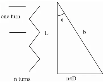
Figure11shows the relation between the parameters of the PMAs. Equations (7), (8) and (9) define the Tondu and Lopez force model under the following assumptions: 1-The shape of the PMA is a perfect cylinder with zero wall thickness. 2- There is a contact between the inner rubber tube and the braided sleeve. 3- The braided strand length is constant. 4- There is no friction between the tube and
Figure 11.The geometrical analysis of the PMA.
the sleeve. 5- Neglecting the latex tube force (Tondu & Lopez,2000).
Where from Figure11:
L=bcosθ, D=bsinθ
nπ , (7)
where b is the strand length and n is the number of strand turns. By considering (7) the strand length can be evaluated as:
b=(L2+(Dnπ)2)12. (8)
The extension forcefcan be calculated as the multiplica-tion of the gauge pressure and the volume change with respect to length.
f = −πr20p[α(1−ε)2−β], (9) whereα= tan32(θ
0) andβ=
1
sin2(θ 0),ε
is the extension
ratio for the extensor PMA.
Moreover, r0 and θ0 represent the initial values of
radius and the braided angle of the PMA respectively. Figure12below shows the experimental force data with the plot of (9) for the 30 cm PMA. This figure illustrates that the difference between the theoretical and experi-mental records has two main causes. The first one is the non-cylindrical shape of the PMA at zero or low applied air pressure. The second reason is that there is no perfect contact between the inner rubber tube and the braided sleeve and the resistance of rubber tube (Al-Ibadi et al.,
2017a). To overcome these two aspects, the correction factor (q) is used and the force formula can be modified as in (11).
[image:7.610.67.292.227.362.2]Figure 12.The experimental and the theoretical force for the 30 cm extensor PMA.
Figure 13.The experimental and the presented theoretical force for the 30 cm extensor PMA.
of (zero force) pressure is (45 kPa). Due to the resis-tance of inner tube against the stretch and the contact-less between the braided sleeve and the inner tube, the energy of actuated air below 45 kPa will be considered as loses, for that the extensor force in (10) is defined to be (0 N) from (0–45 kPa) and the gauge pressure shift by (45 kPa) otherwise. The zero force pressure is stud-ied by Tsagarakis and Caldwell (2000) as a function of pressure and inner tube diameter. Here, it is found that this constant value could be considered for this type of PMAs.
Taking these two factors into account gives substan-tial matching between the experimental and theoretical force characteristics. The force of all actuators under study has been validated and Figure13gives the force plot for the (30 cm) PMA.
The modification of (10) shows in (11) below:
f =0, 0≤p≤45 kPa,
f = −πr2o(p−45)[α(1−qε)2−β], p≥45. (11)
6. Load effects on actuator behaviour
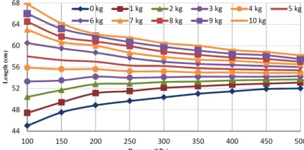
[image:8.610.321.545.51.167.2]Attaching load to the extensor PMA changes its exten-sion ratio. Figure14shows the length of the actuator with respect to the attached load at gauge pressure (100–500) kPa. Increasing the attached load gives the PMA more
Figure 14.The length of 30 cm extensor PMA as a function of the attached load at different pressurized condition.
Figure 15.The length of the actuators against the pressure at fixed weight values.
ability to extend at low pressure (p). In this figure, all lines intersect around (3.5) kg.
The load test is done as follows: a- Attached different loads up to 10 kg in 0.5 kg steps at 100 kPa. b- Increase the pressure to 500 kPa in 50 kPa steps and repeat step (a) each time. Figure15shows that the behaviour of the muscle is changed after load 3.5 kg, where increasing the gauge pressure makes the PMA act as a contraction instead of an extension muscle.
From Figures14and15, the extensor muscle might be used as a contractor actuator when it is loaded with more than 3.5 kg.
[image:8.610.66.291.215.325.2] [image:8.610.320.541.227.336.2]86 A. AL-IBADI ET AL.
7. Extensor continuum arm
The traditional way in which PMAs are used is to produce a linear contraction or extension. However, this section explores using the extensor actuator in such a manner that when activated, it bends.
McMahan et al. (2006) explain that using the principle of the constant-volume creates the bending behaviour of the extensor PMA, where the dimensional adjustment on one side leads to a dimensional modification on another side.
To achieve the bending behaviour for the extension PMA, a high-tension thread is used to fix one side of the actuator, which prevents it from extending, while the other sides are free to elongate. The whole muscle will bend toward the thread side when pressurized. Figure16
shows a 30 cm extensor actuator and how it bends at 300 kPa air pressure. The air pressure has been applied gradually from zero to 500 kPa through a solenoid valve and the bending angle is recorded by the MPU 6050 sen-sor. The maximum bending angle for the single extensor actuator is about 450° at 500 kPa at the no-load condition and the maximum bending payload is 2.0 kg.
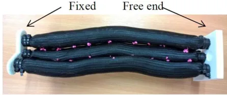
[image:9.610.319.542.50.144.2]To develop the bending in all directions a 4-PMAs continuum arm is designed and constructed as shown in
Figure 18.Four 30 cm extensor PMAs continuum arm.
Figures17and18. Four extension actuators 30 cm each are used; one in the centre and the others are located at 3 cm from the centre and 120° between each other.
A Solidworks 2015 is used to design the two ends, and a 3D printer is used to print them. Then the centre actua-tor is connected to others individually. Equal air pressure in all PMAs makes the arm extend in a straight direc-tion, while, the different pressure inside the four actuators make the free end move in all direction in the space at almost constant curvature (Walker, 2013). The position angle is observed as a function of the supplied pressure and the attached load.
[image:9.610.125.489.384.519.2]Firstly, the experiments are done by recording the ini-tial angle of the free end (δ), which it is equal to (zero)
[image:9.610.127.485.550.715.2]Figure 16.A 30 cm extensor PMA (a) one side sewed actuator (b) bending under 300 kPa air pressure.
degree due to a straight-line arm. Secondly, all PMAs are actuated by (45 kPa), then the pressure is increased in one of the PMAs in the corner. The arm will then bend into another position, depending on the amount of the pres-sure in the muscle. Andδis recorded each time. Figure19
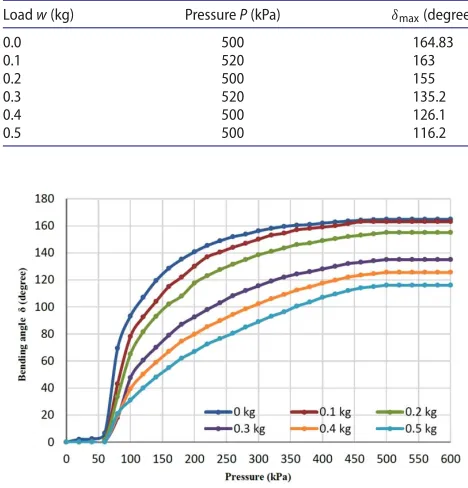
shows the extension arm under actuation of 300 kPa. The maximum angle value (δmax) depends on the
amount of the attached load (w) to the arm end. Table2
below shows different maximum angles with different load values.
[image:10.610.317.543.201.458.2]The bending angle against the air pressure at different load values is illustrated in Figure20which it represents the position of the free end at any pressure step.
[image:10.610.80.274.247.396.2]Figure 19.An extensor continuum arm at 300 kPa.
Table 2.Maximum angle at different loads.
Loadw(kg) PressureP(kPa) δmax(degree)
0.0 500 164.83
0.1 520 163
0.2 500 155
0.3 520 135.2
0.4 500 126.1
0.5 500 116.2
Figure 20.The bending angle against the pressure at different load conditions.
From these data, the bending angle increase when the applied pressure increase and its value at each air pressure step depends on the attached load. In our exper-iment, various loads from 0 to 0.5 kg are attached. Fur-thermore, the arm starts to bend when the air pressure reaches 80 kPa and the angle has a fixed value (δmax)
over 520 kPa. As a result, the operation range will be at pressure values from 80–520 kPa.
A new formula of the proposed extensor soft arm bending angle (12) is presented as a function of the input air pressure and the amount of attached load as follows:
δ=a− b
1+p
c
de (12)
where ⎡ ⎢ ⎢ ⎢ ⎢ ⎢ ⎢ ⎢ ⎢ ⎣ a b c d e ⎤ ⎥ ⎥ ⎥ ⎥ ⎥ ⎥ ⎥ ⎥ ⎦ = ⎡ ⎢ ⎢ ⎢ ⎢ ⎢ ⎢ ⎢ ⎢ ⎢ ⎣
173.57 −350.13 9014
−172.1 312.6 −8667.6 0.5798 2.2097 −33.363 303.74 −5310.1 36922 0.0045 −0.0727 6.4529
−62973 167422 −148110 61529 −164591 145972 201.17 −499.34 431.94
−118935 183790 −111871
−43.867 103.32 −81.375
⎤ ⎥ ⎥ ⎥ ⎥ ⎥ ⎥ ⎥ ⎥ ⎦ ⎡ ⎢ ⎢ ⎢ ⎢ ⎢ ⎢ ⎢ ⎢ ⎢ ⎢ ⎢ ⎣ 1 w w2 w3 w4 w5 ⎤ ⎥ ⎥ ⎥ ⎥ ⎥ ⎥ ⎥ ⎥ ⎥ ⎥ ⎥ ⎦ .
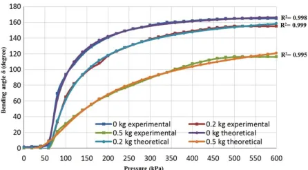
Equation (12) above gives the bending angle at any air pressure amount from 0–600 kPa, while, the value of the parameters (a, b, c, d and e) depends on the attached load. The parameters of (12) have been found by curve fitting the parameters of the bending angle at each sin-gle load to generalised the bending ansin-gle formula for the proposed extensor continuum arm.
This formula is validated for all load conditions and Figure21gives the validation results for three conditions (0, 0.2 and 0.5 kg). This figure shows a significant match-ing between the experimental results and the presented formula.
8. Kinematics of the extensor continuum arm
The bending direction of the proposed arm depends on which extensor actuator is activated. Figure22shows the geometrical analysis of the actuators positions and the bending directions.
[image:10.610.59.293.459.703.2]88 A. AL-IBADI ET AL.
[image:11.610.64.291.218.333.2]Figure 21.The validation results for the bending angle at three different load conditions.
Figure 22.The geometrical analysis of the extensor continuum arm.
is in the direction of the positive Y-axis (i.e. the extensor continuum arm will bend towards 90°). The bending due to the first actuator can be written as: (δ1∠90◦).Similarly,
the bending angles of the second and third actuators are defined as: (δ2∠330◦) and (δ3∠210◦) respectively. And the
resultant bending angle of the arm can be defined as:
δ∠θ=δ1∠90◦+δ2∠330◦+δ3∠210◦, (13)
whereδ1,δ2 andδ3are the bending angles of the soft
arm due to the pressurized condition of the actuators 1, 2 and 3 respectively, and they calculated according to (12). The bending angleδ of the proposed extensor contin-uum arm in the direction ofθ can be found anytime by applying (13).
Figure 19 shows three operation zones, each one represents the operation area for two actuators. The pre-sented arm covers (zone1) when the actautor1 and actua-tor3 are activated. Similarly, pressurizing actuators 1 and 2 cover (zone2), and (zone3) is covered by actuators 2 and 3. Consequently, pressurizing the three actuators by differ-ent air pressure values makes the continuum arm moves to any of these zones according to (13).
9. Conclusion
This article presented full descriptions of design and implementation of the single extensor pneumatic muscle
actuator. The elongation performance of this actuator is explained for different sizes. Then a novel mathematical model is proposed and validated by different sets of data and a neural network control system.
On the other hand, the load effect is explained by attaching different load values to the actuator. This exper-iment shows that the actuator behaviour converted to the contraction at 3.5 kg due to the decreasing in the braided angle. The experimental data gives the capability to use the extensor actuator as a contractor at a specif-ically attached load. This ability makes this type of PMA appropriate for multiple purposes.
The extension force for the extensor PMA is presented according to its structure taking into account the needed amount of air pressure to develop the force.
An extensor arm is built from four extensor PMAs and we studied its behaviour for bending. The experiments show high bending angle at load up to 0.5 kg. A for-mula for this bending angle is presented for no-load and load conditions. The validation of this formula shows a significant accuracy for the air pressure more than 80 kPa. The kinematics for the presented soft arm is explained by the bending angle and its direction for any pres-surizing conditions.
As a future work, a control system might be applied to the extensor soft arm to control the bending angle of the arm and its direction.
Disclosure statement
No potential conflict of interest was reported by the authors.
ORCID
Alaa Al-Ibadi http://orcid.org/0000-0002-0779-8217
References
Ahn, K. K., & Nguyen, H. T. C. (2007). Intelligent switching con-trol of a pneumatic muscle robot arm using learning vector quantization neural network.Mechatronics,17, 255–262. Al-Ibadi, A., Nefti-Meziani, S., & Davis, S. (2016). Valuable
exper-imental model of contraction pneumatic muscle actuator. In
2016 21st IEEE International Conference on Methods and Models in Automation and Robotics (MMAR), Poland, pp. 744–749. Al-Ibadi, A., Nefti-Meziani, S., & Davis, S. (2017a). Efficient
structure-based models for the McKibben contraction pneu-matic muscle actuator: The full description of the behaviour of the contraction PMA.Actuators,6, 32.
Al-Ibadi, A., Nefti-Meziani, S., & Davis, S. (2017b). Novel models for the extension pneumatic muscle actuator performances. In2017 23rd International Conference on Automation and Com-puting (ICAC), pp. 1–6.
Bailly, Y., & Amirat, Y. (2005). Modeling and control of a hybrid continuum active catheter for aortic aneurysm treatment. In
Robotics and Automation, 2005. ICRA 2005. Proceedings of the 2005 IEEE International Conference on, pp. 924–929.
Chou, C.-P., & Hannaford, B. (1996). Measurement and modeling of McKibben pneumatic artificial muscles.IEEE Transactions on Robotics and Automation,12, 90–102.
Davis, S., & Caldwell, D. G. (2006). Braid effects on contractile range and friction modeling in pneumatic muscle actuators.
The International Journal of Robotics Research,25, 359–369. Fan, J., Zhong, J., Zhao, J., & Zhu, Y. (2015). BP neural network
tuned PID controller for position tracking of a pneumatic artificial muscle.Technology and Health Care,23, S231–S238. Godage, I. S., Branson, D. T., Guglielmino, E., & Caldwell, D. G.
(2012). Pneumatic muscle actuated continuum arms: Mod-elling and experimental assessment. In 2012 IEEE Interna-tional Conference on Robotics and Automation (ICRA), pp. 4980–4985.
Hannan, M. W., & Walker, I. D. (2003). Kinematics and the imple-mentation of an elephant’s trunk manipulator and other con-tinuum style robots.Journal of Field Robotics,20, 45–63. Jones, B. A., & Walker, I. D. (2006). Kinematics for multisection
continuum robots.IEEE Transactions on Robotics,22, 43–55. Liu, W., & Rahn, C. (2003). Fiber-reinforced membrane
mod-els of McKibben actuators.Journal of Applied Mechanics,70, 853–859.
Margheri, L., & Trimmer, B. (2014). Soft robotics community events: Meeting different backgrounds for common chal-lenges.Soft Robotics,1, 236–238.
McMahan, W., Chitrakaran, V., Csencsits, M., Dawson, D., Walker, I. D., Jones, B. A.,. . .Rahn, C. D. (2006). Field trials and testing
of the OctArm continuum manipulator. InProceedings 2006 IEEE International Conference on Robotics and Automation, 2006. ICRA 2006, pp. 2336–2341.
McMahan, W., Jones, B. A., & Walker, I. D. (2005). Design and implementation of a multi-section continuum robot: Air-Octor. In2005 IEEE/RSJ International Conference on Intelligent Robots and Systems, 2005.(IROS 2005), pp. 2578–2585. Mutlu, R, Yildiz, S. K., Alici, G., Marc in het Panhuis, & Spinks,
G.M.2016. Mechanical stiffness augmentation of a 3D printed soft prosthetic finger. In2016 IEEE International Conference on Advanced Intelligent Mechatronics (AIM), pp. 7–12.
Neppalli, S., & Jones, B. A. (2007). Design, construction, and analysis of a continuum robot. InIntelligent Robots and Sys-tems, 2007. IROS 2007. IEEE/RSJ International Conference on, pp. 1503–1507.
Pillsbury, T. E., Guan, Q., and Wereley, N. M.2016. Compari-son of contractile and extensile pneumatic artificial muscles. In2016 IEEE International Conference on Advanced Intelligent Mechatronics (AIM), pp. 94–99.
Tondu, B., & Lopez, P. (2000). Modeling and control of McK-ibben artificial muscle robot actuators.IEEE Control Systems,
20, 15–38.
Trivedi, D., Rahn, C. D., Kier, W. M., & Walker, I. D. (2008). Soft robotics: Biological inspiration, state of the art, and future research.Applied Bionics and Biomechanics,5, 99–117. Tsagarakis, N., & Caldwell, D. G. (2000). Improved modelling and
assessment of pneumatic muscle actuators. InIEEE Interna-tional Conference on Robotics and Automation, 2000. Proceed-ings. ICRA’00, pp. 3641–3646.