A parallel process model and architecture for a Pure Logic
Language
JELLY, Innes E.
Available from Sheffield Hallam University Research Archive (SHURA) at:
http://shura.shu.ac.uk/8778/
This document is the author deposited version. You are advised to consult the publisher's version if you wish to cite from it.
Published version
JELLY, Innes E. (1990). A parallel process model and architecture for a Pure Logic Language. Doctoral, Sheffield City Polytechnic.
Copyright and re-use policy
100311425 3 TELEPEN
mes are charged at
50
p per
\
( 3 5 ° ^ Sheffield City Polytechnic Library
ProQuest Number: 10697177
All rights reserved
INFORMATION TO ALL USERS
The quality of this reproduction is dependent upon the quality of the copy submitted.
In the unlikely event that the author did not send a com plete manuscript and there are missing pages, these will be noted. Also, if material had to be removed,
a note will indicate the deletion.
uest
ProQuest 10697177
Published by ProQuest LLC(2017). Copyright of the Dissertation is held by the Author.
All rights reserved.
This work is protected against unauthorized copying under Title 17, United States C ode Microform Edition © ProQuest LLC.
ProQuest LLC.
789 East Eisenhower Parkway P.O. Box 1346
A Parallel Process Model and Architecture for a Pure Logic Language
by
InnesE. Jelly MA, MSc
A thesis submitted to the Council for National Academic Awards in partial fulfilment of the requirements for the degree of Doctor of Philosophy.
Sponsoring Establishment : School of Computing and M anagement Sciences, Sheffield City Polytechnic
Collaborating Establishment : ICLplc
Contents
Contents...i
List Of Figures...xiii
Acknowledgments... xvii
Abstract... xviii
Chapter One Introduction...1
1.1. Introduction to the Project... 1
1.2. The Project... 2
1.2.1. Background to the Project... 2
1.2.2. Aims of the Project... 4
1.2.3. Development and Achievements of the Project...4
1.3. Organisation of the Thesis ... 8
Chapter Two
Parallelism in Knowledge Based Systems and Logic Languages...10
2.1. Introduction... 10
2.2. Knowledge Based Systems... 11
2.2.1. Introduction...11
2.2.2. Logic Programming...14
2.2.3. Deductive Databases...16
2.2.4. Datalog Programs... 21
2.2.5. Implementation of Logic Based Knowledge Bases... 21
2.2.6. Implementation of Prolog... 23
2.3. Parallelism in Logic Languages...28
2.3.1. Introduction... 28
2.3.2. Concurrency and Parallelism...29
2.3.3. Control of Parallelism...30
2.3.4. Sources of Parallelism...31
2.3.4.1. Introduction...31
2.3.4.2. Search Parallelism... 31
2.3.4.3. OR Parallelism...32
2.3.4.4. AND Parallelism... 34
2.3.4.5. Stream Parallelism... 38
2.3.5. Potential Performance Benefits from Parallel Execution...38
Chapter Three
Parallel Logic Systems and Associated Architectures...42
3.1. Parallel Logic Language Systems... 42
3.1.1. Introduction... 42
3.1.2. AND Parallel Systems... 44
3.1.2.1. Introduction... 44
3.1.2.2. Transparent AND Parallelism...45
3.1.2.3. Programmer Control of AND Parallelism... 48
3.1.3. OR Parallel Systems... 52
3.1.3.1. Introduction... 52
3.1.3.2. Data Sharing OR Parallel Systems... 54
3.1.3.3. Non Shared Data OR Parallel Systems...56
3.2. Architectural Proposals for Multiprocessor Machines...60
3.2.1. Introduction... 60
3.2.2. Computational Requirements for Parallel Architectures...61
3.2.3. Design Methodology for Multiprocessor Architectures...62
3.2.4. Shared versus Non Shared Memory Architectures 63 3.2.4.1. Introduction... 63
3.2.4.2. Shared Memory Systems... 63
3.2.4.3. "Intermediate" System Proposals... 65
3.2.4.4. Non Shared Memory Systems...66
\~ um cni.s
Chapter Four
The Pure Logic Language... 70
4.1. Introduction... 70
4.2. Development of the Pure Logic Language...71
4.3. Rewrite Rules... 71
4.4. The Pure Logic Language... 72
4.5. The Interpreter... 73
4.5.1. Rule Rewriting...73
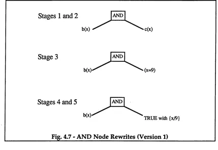
4.5.2. AND Node Rewriting...76
4.5.3. OR Node Rewriting... 76
4.5.4. IN Node Rewriting... 77
4.5.5. NOT Node Rewriting... 77
4.5.6. User Defined Rule Rewriting...78
4.5.7. Future Optimisation of Rewrite Execution... 79
4.6. The Implementation of the Interpreter...79
4.6.1. Introduction...79
4.6.2. Memory Management Data Structures in the Interpreter... 80
4.6.2.1 The System Stack...80
4.6.2.2. The OR Stack...82
4.6.2.3. The Variable List... 82
4.6.2.4. The Binding List... 82
4.6.3. The Parser... 83
4.6.4. The "Core” or Rewrite Manager Module...86
4.7. Comparison of PLL and Prolog Implementations... 88
Chapter Five
The Parallel Pure Logic Language... 92
5.1. Introduction... 92
5.2. Parallelism within the Pure Logic Language... 93
5.3. The Parallel Process Model of the PLL... 95
5.3.1. The Requirements of the Model...95
5.3.2. The Definition of the Computational Model... 97
5.4. The Implementation of the Parallel Process Model... 101
5.4.1. Introduction... 101
5.4.2. Modelling the Parallel Interpreter on a Single Processor... 103
5.4.3. Process Representation...104
5.4.4. Process Spawning... 109
5.4.4.1. Introduction...109
5.4.4.2. Rewriting of OR Nodes...109
5.4.4.3. Rewriting of IN Nodes...110
5.4.4.4. Rewriting of RANGE Nodes...I ll 5.4.4.5. Rewriting of Conjunctions...112
5.4.5. Process Reconstruction...116
5.5. Summary... 118
Chapter Six
The Parallel Architecture...119
6.1. Introduction... 119
6.2. Fixed Topology Architectures... 120
6.3. Functional Requirements of the Multiprocessor Architecture...123
6.4. Functional Design of the Multiprocessor Architecture... 124
6.4.1. Introduction... 124
6.4.2. Query Evaluation...125
6.4.3. Data Packet Definition... 126
6.4.4. Size of Data Packet...129
6.4.5. Data Packet Implementation...133
6.5. A Bus Based Multiprocessor Architecture... 135
6.5.1. Introduction...135
6.5.2. The Multiple Bus Broadcasting System ...137
6.5.3. The Processing Elements... 139
6.5.4. The Controller...142
6.5.5. Communication Estimates... 143
6.5.6. Base Predicate Storage... 144
6.5.7. Multitasking...144
( / I f
Chapter Seven
The Simulation of the System...146
7.1. Introduction... 146
7.2. The Role of Simulation in the Design Process...146
7.2.1. Model Formation and Evaluation... 146
7.2.2. Simulation Design... 147
7.3. The Requirements of the Parallel System Simulation...148
7.4. The Parallel System Simulation Design...149
7.4.1. Introduction... 149
7.4.2. Machine Data Structures...152
7.4.3. Functional Design of the Simulation...156
7.4.3.1. Introduction...156
7.4.3.2. The Prototype Simulation... 156
7.4.3.3. Timing Data... 158
7.4.3.4. A Better Representation of Concurrency... 160
7.4.4. The Full Simulation... 163
7.5. Summary...165
Chapter Eight Preliminary Testing and Results... 166
8.1. Introduction... 166
8.2. Testing of the System Design... 167
8.3. Required Results...168
8.3.1. Introduction...168
8.3.2. Rewrite Interpreter Timings...168
8.3.3. Machine Performance Data... 169
8.3.4. Results Summary...170
8.4. Benchmark Tests... 171
8.4.1. Requirements in Benchmarking... 171
8.4.2. Test Programs... 172
8.5. Initial Benchmark Testing...173
8.5.1. Introduction...173
8.5.2. Processing and Data Transmission Times... 175
8.5.3. Simulation Overheads...176
8.5.4. Spawning Overheads... 177
8.5.5. Rewriting Overheads... 178
8.6. Summary... 180
Chapter Nine
Tests and Results from the Modified Parallel PLL System...181
9.1. Introduction... 181
9.2. The Performance of the Rewrite Interpreter... 181
9.3. Function Calling Overheads...183
9.3.1. Measurement of Function Calling... 183
9.3.2. Allowance for Function Calling Overheads... 185
9.4. Results of Revised Tests...186
9.4.1. Introduction... 186
9.4.2. Revised Performance of the Interpreter...186
9.4.3. Implications for Further Testing... 188
9.4.4. Details of Function Calls in the Rewrite Interpreter 189 9.5. Additional Tests on Machine Performance... 192
9.5.1. Return of Results... 192
9.5.2. Input Memory Usage... 193
9.5.3. Load Balancing Strategies... 195
9.6. Performance Benefit due to Parallel Execution... 198
9.7. Communication Delays...200
Wi/ If f i / l f f u
Chapter Ten
Evaluation of the Project... 202
10.1. Introduction... 202
10.2. The Parallel Pure Logic Language System Design... 202
10.2.1. The Parallel Rewrite Interpreter... 202
10.2.2. The Bus Based Multiprocessor Architecture... 206
10.3. Research Methods and Project Organisation...209
10.3.1. Introduction...210
10.3.2. Background Work... 212
10.3.3. Analysis and Specification of the System Requirements... 214
10.3.4. Implementation...215
10.3.5. Testing...216
10.4. Assessment of Programming Environments...217
10.5. Future Work ... 219
10.6. Summary... 222
Chapter Eleven Conclusion...223
Bibliography...225
Appendices
Appendix A
Lexical Conventions for the Representation of Logic... 240
Appendix B Pure Logic Language Syntax...241
Bl. Introduction... 241
B2. Pure Logic Language Definition...241
B2.1. Symbols and Delimiters...241
B2.2. Identifiers and Numbers...241
B2.3. Structures...242
B2.4. Predicates and Operators...242
B2.5. Expressions...242
B2.6. Command Line Interface...243
Appendix C PLL Programs Used for Benchmark Testing... 244
Cl. Program 1 - Family Database... 244
C2. Program 2 - Map Colouring and Other Sample Definitions 244 Appendix D Analysis of Potential AND Parallelism in PLL Programs...246
Appendix F
The Parallel Simulation Software...252
FI. Introduction... 252
F2. The Parallel Machine Emulation Module...252
F2.1. Introduction... 252
F2.2. Data Structures... 253
F2.2.1. Machine Emulation Structures... 253
F2.2.2. Process Representation...254
F2.3. Machine Emulation Functions... 254
F2.3.1. Function: Parallel_System_Driver... 254
F2.3.2. Function: Evaluate_Process...255
F2.3.3. Function: Call_Interpreter...255
F2.3.4. Function: Distribute_New_Processes...255
F2.3.5. Low Level Functions... 255
F2.3.5.1. Basic Functions...255
F2.3.5.2. Queue Manipulation Functions... 259
F2.3.5.3. Process Creation and Manipulation Functions... 259
F2.3.5.4. Packet Communication Calculation Functions... 261
F2.3.5.5. Timing Functions... 261
F2.3.5.6. Memory Management and Checking Functions... 261
F2.3.5.7. Machine Configuration and Initialisation Functions...261
F2.3.5.8. Allocation and Distribution Functions... 262
F3. The Parallel Rewrite Manager Module...262
F3.1. Introduction...262
F3.2. Top Level Rewrite Function...263
F3.3. Node Rewrite or Eval Functions... 263
F3.3.1. Conjunction Rewriting... 263
Appendix G
Test Results... 271
Gl. Introduction... 271
G2. Data Interpretation Program...272
G3. Total Query Evaluation Times...276
G4. Process Times... 289
G5. Function Call Details... 299
G6. Bus Usage Results...303
G7. Input Memory Utilisation... 308
G7. Return of Results...315
Appendix H PLL Program for "AND" Queries... 321
Appendix I C Program for Measuring Function Calling Overheads... 322
Appendix J The 3L Parallel C System on the Transputer... 329
Jl. Introduction... 329
J2. The Transputer...329
List of Figures
Fig. 1.1 - Project Overview... 5
Fig. 2.1 - Relational Database and Prolog Program... 13
Fig. 2.2 - Resolution Search Tree...15
Fig. 2.3 - Relational Database with Derived Relation... 18
Fig. 2.4 - Deductive Database Implementation... 20
Fig. 2.5 - Compiled Prolog Code... 25
Fig. 2.6 - WAM Memory Organisation... 27
Fig. 2.7. - WAM Registers... 28
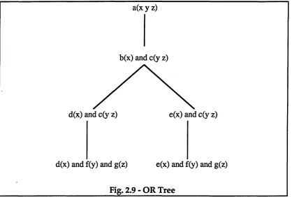
Fig. 2.8-ORTree...32
Fig. 2.9 - OR Tree...33
Fig. 2.10 - AND-OR Tree... 35
Fig. 2.11 - AND-OR Tree with Shared Variables... 36
Fig. 2.12 - AND-OR Tree for Student-Teacher Program...37
Fig. 2.13 - Measurements of Potential OR Parallelism... 39
Fig. 3.1 - Summary of Parallel Logic Systems... 43
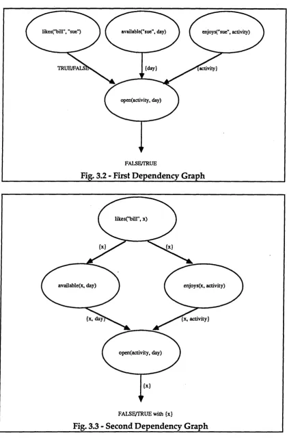
Fig. 3.2 - First Dependency Graph...46
Fig. 3.3 - Second Dependency Graph... 46
Fig. 3.4 - Third Dependency Graph...47
Fig. 3.5 - Representation of Binding Windows...55
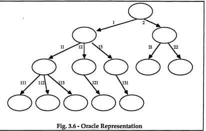
Fig. 3.6 - Oracle Representation...59
Fig. 3.7 - Aurora Prolog / Encore Multimax Speedups...65
Fig. 4.1 - AND Node Expression Tree...74
Fig. 4.2 - PLL System Stack...81
Fig. 4.3 - AND Node Representation... 84
Fig. 4.5 - Rule Representation...85
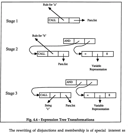
Fig. 4.6 - Expression Tree Transformations... 87
Fig. 4.7 - AND Node Rewrites (Version 1)...90
Fig. 4.8 - AND Node Rewrites (Version 2)... 90
• • •
Fig. 5.1 - Expression Tree...96
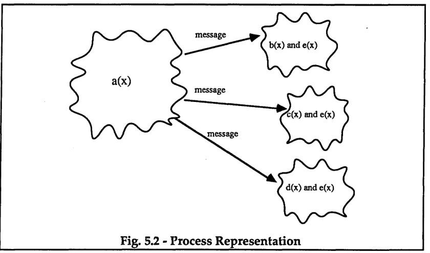
Fig. 5.2 - Process Representation... 98
Fig. 5.3 - Process Structure...105
Fig. 5.4 - OR Expression Tree...106
Fig. 5.5 - Process Descriptions... 106
Fig. 5.6 - Process Description...106
Fig. 5.7 - Expression Tree... 106
Fig. 5.8 - NOT Node Rewrite...107
Fig. 5.9 - Process Representation (Second Level)...108
Fig. 5.10 - Process Description Formation...110
Fig. 5.11 - IN Node Transformation... Ill Fig. 5.12 - Expression Tree with AND and OR Nodes... 113
Fig. 5.13 - Initial Process Descriptions... 113
Fig. 5.14 - Completed Process Descriptions...113
Fig. 5.15 - Rewriting of Expression Tree with AND and OR Nodes... 114
Fig. 5.16 - Partial Process Descriptions...115
Fig. 5.17 - Extended Process Descriptions...115
Fig. 5.18 - Completed Process Descriptions...115
Fig. 5.19 - Initial Process Description Implementation...116
Fig. 5.20 - Final Process Description Implementation... 116
Fig. 5.21 - Process Description... 117
Fig. 5.22 - AND Expression Tree... 117
Fig. 5.23 - Bindings Representation... 118
Fig. 6.1 - PLL Query Solution Tree... 122
Fig. 6.2 - Functional Outline of Multiprocessor Machine...125
Fig. 6.3 - Data Packet Representation...127
Fig. 6.4 - Combined Data Packet... 129
Fig. 6.5 - Rule Storage Data... 131
Fig. 6.6 - Data Packet Type Sizes...133
Fig. 6.7 - Process Representation (Third Level)...134
Fig. 6.8 - Functional Design of Extended Multiprocessor Machine... 136
Fig. 7.1 - Data Flow between Parallel PLL System Modules...151
Fig. 7.2 - Machine Data Structures...153
Fig. 7.3 - Process Representation...154
Fig. 7.4 - Process Record Representation... 155
Fig. 7.5 - Allocation Record Representation ...155
Fig. 7.6 - Timing of Process Execution...161
Fig. 7.7 - Functional Design of Simulation Software... 164
Fig. 8.1 - Total Query Evaluation Times in ms (Initial Test Series)...174
Fig. 8.2 - Average Process Timings with Query aunt(x y)?...175
Fig. 8.3 - AND Query Evaluation Times...179
Fig. 9.1 - Testing Summary with Chapter/Section References...182
Fig. 9.2 - Timing of Functions... 184
Fig. 9.3 - Effects of Parameters on Function Times... 185
Fig. 9.4 - Average "Optimised" Process Timings for Query aunt(x y)?... 187
Fig. 9.5 - Total Query Evaluation Times for "Optimised" Version...187
Fig. 9.6 - Numbers of Function Calls within Processes... 190
Fig. 9.7 - Function Group Percentage during Rewrite Phase... 191
Fig. 9.8 - Maximum Input Memory Usage with Query firstcousin(x y)?...194
Fig. 9.9 - Total Evaluation Times in ms with Random Scheduling...196
Fig. 9.10 - Schematic Representation of Processor Usage... 196
Fig. 9.12 - Graph of Performance Speedups... 199
Fig. 9.13 - Total Query Evaluation Times for "Scaled" System... 200
Fig. 10.1 - Representation of Different PLL Memory Mapping Views... 211
Fig. 10.2 - Simulating the Parallel Machine Design...213
Fig. D1 - Code for "route" rules...246
Fig. D2 - Expression Tree for Query route(2 4 r)?... 247
Fig. El - "Reduced" Rule Base... 249
Fig. E2 - Solution Tree... 250
Fig. FI - Top Level Functions...253
Fig. F2 - Code for <parallel_system_driver>...256
Fig. F3 - Code for <evaluate_process>...257
Fig. F4 - Code for <call_interpreter>...258
Fig. F5 - Code for <distribute_new_processes>... 260
Fig. F6 - Function Calling in the Parallel Rewrite Manager...263
Fig. F7 - Code for <rewrite_expP>...264
Fig. F8 - Code for <eval_andP>... 266
Fig. F9 - Code for <eval_orP>...267
Fig. F10 - Code for Spawning Functions... 267
Fig. Fll - Code for <eval_inP>... 268
Fig. FI 2 - Code for <transform_in_node>... 268
Fig. FI3 - Code for <eval_rangeP>... 269
Fig. F14 - Code for <transform_range_node>... 270
Fig. J1 - The Transputer System... 330
Acknowledgments
This reseach project was funded under Project No. 086/178 by the Alvey Commision with ICL pic designated as industrial "uncle".
I should like to thank my Director of Studies, John Brown, for his interest, advice and many contributions to the project; my supervisor, Ian Morrey, for his support and encouragement; Ed Babb and his team at ICL for their interest and generous help; the research staff at Sheffield City Polytechnic for their companionship and advice, especially Jonathan Gray for his help with Transputer technology and Roger Spall for imparting his desktop publishing skills. Finally thanks are due to my husband and children for their patient support during the preparation of this thesis.
Abstract
The research presented in this thesis has been concerned with the use of parallel logic systems for the implementation of large knowledge bases. The thesis describes proposals for a parallel logic system based on a new logic programming language, the Pure Logic Language. The work has involved the definition and implementation of a new logic interpreter which incorporates the parallel execution of independent OR processes, and the specification and design of an appropriate non shared memory multiprocessor architecture.
The Pure Logic Language which is under development at ICL, Bracknell, differs from Prolog in its expressive powers and implementation. The resolution based Prolog approach is replaced by a rewrite rule technique which successively transforms expressions according to logical axioms and user defined rules until no further rewrites are possible.
A review of related work in the field of parallel logic language systems is presented. The thesis describes the different forms of parallelism within logic languages and discusses the decision to concentrate on the efficient implementation of OR parallelism. The parallel process model for the Pure Logic Language uses the same execution technique of rule rewriting but has been adapted to implement the creation of independent OR processes and the required message passing operations. The parallelism in the system is implemented automatically and, unlike many other parallel logic systems there are no explicit program annotations for the control of parallel execution. The spawning of processes involves computational overheads within the interpreter: these have been measured and results are presented.
Chapter One
Introduction
1.1. Introduction to the Project
The use of logic as a programming language developed out of work on automated theorem proving in the 1960s and 1970s: in recent years logic languages in particular Prolog have moved from being research tools to providing the facilities and performance expected from modern programming environments. However although the performance of many current Prolog systems has been improved with the introduction of sophisticated compiler techniques, the type of application in which Prolog is used often makes heavy computational demands on the system. This situation is typical of many programs employed in the field of artificial intelligence where extensive pattern matching operations are involved in the processing [Charniak 85]. Applications of this type include expert systems, natural language processing, deductive databases and other knowledge based systems [Frost 86].
The involvement of high computational demands in many logic language applications has led to research into the parallel execution of these programs. The underlying premise has been that by dividing the programming task into separate computational units which can be executed simultaneously, the overall performance can be improved. There has been a considerable amount of research into the definition of parallel logic languages and the design of suitable multiprocessor architectures, and this project contributes to the work in both of these areas.
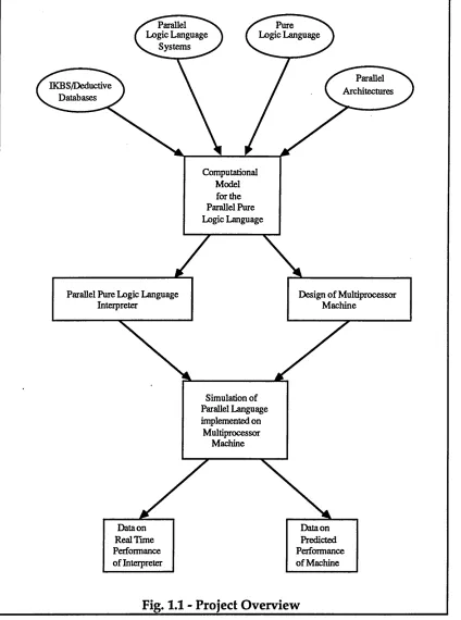
onto the parallel architecture, has been produced and measurements on the predicted performance of the system obtained.
The project evolved out of work done at Sheffield City Polytechnic and the Systems Strategy Centre of ICL on parallel architectures and logic language execution and this is considered in the next section which presents the background to the project. This is followed by a discussion on the aims and development of the project. The final section of the chapter describes the organisation of the thesis.
1.2. The Project
1.2.1. Background to the Project
The starting point for this project has been research done at Sheffield City Polytechnic on the design of multiprocessor architectures and work by the Logic Language Research Group at ICL, Bracknell, into the development of a new logic programming language known as the "Pure Logic Language" [Babb 89a]. These two interests were brought together in a three year Alvey funded project centred at Sheffield City Polytechnic with ICL acting as industrial "uncle".
The research at Sheffield into multiprocessor architectures had been initiated by an interest in data flow programs and the first proposals were for a fine grained non shared memory parallel computer to support this type of application [Loh 82]. This architecture consisted of a fixed two dimensional grid of processing nodes thus providing nearest neighbour connections. Speedy transmission of data through the grid was implemented by having a dedicated message handling processor in each processing node in addition to the actual "working" processor. A simulation of this architecture was produced.
knowledge bases were established in 1986. In the first the method for knowledge representation was to be frame based [Brown 87], [Brown 88], [Saeedi 90]; the second project which forms the subject of this thesis was originally defined as "The Implementation of Large Knowledge Bases and Logic Programming Languages on Multiprocessor Architectures" [Jelly 87], [Jelly 88].
On the architectural front the original hope was that the type of fine grained multiprocessor design that had evolved for use with these other applications would prove suitable for implementing a logic language system and that a parallel version of the Pure Logic Language could be mapped to the existing simulation.
The work at ICL on the execution of logic has its origins in database research. The need to define correct and secure database systems which could be extended to include inferencing capacity led to the development of a new logic system [Babb 86a]. This reflected the growing interest in deductive databases in the research community [Gallaire 78], [Gallaire 84], [Minker 88]. Because of problems associated with its operational semantics Prolog was not felt to provide a satisfactory basis for this work and research was initiated to develop a new logic language interpreter which would execute "pure" logic [Babb 86b]. The research at ICL has resulted in the definition of a new language, the Pure Logic Language, and its implementation in the form of an interpreter. Unlike Prolog which is resolution based this interpreter uses a rule rewriting approach: logic expressions are successively transformed by the application of rewrite rules [Nairn 87]. These are of two types: inbuilt system rules and user defined rules, the latter corresponding to the logic program. This is discussed fully in Chapter 4.
1.2.2. Aims of the Project
The project was set up to bring together work on parallel architectures, knowledge representation and the execution of logic. The hope was that because of its declarative approach to the execution of logic, the Pure Logic Language would prove suitable for defining knowledge based systems. It was recognised that deductive databases and knowledge based systems could be realised by the use of logic programs, and that the programs involved showed some common features. In general they had a comparatively small number of rules and a large number of base predicates. It was one of the aims of the project to consider the implications of this feature for parallel execution of these programs. The intention was to develop a parallel computational model for the Pure Logic Language based on the study of the type of logic programs employed in knowledge based implementations.
The other aim of the project was to consider the design of multiprocessor architectures in the context of parallel logic language execution. It was soon realised that the original fixed grid type of architecture was not ideal for a parallel version of the Pure Logic Language because the topology did not support the type of message passing required, and the idea of mapping a new parallel interpreter onto the original simulation was abandoned. The task became that of identifying the functional requirements for a parallel system and translating them into a new multiprocessor design [Brown 89].
1.2.3. Development and Achievements of the Project
I
----Parallel Logic Language
Systems
Pure Logic Language
Parallel Architectures IKBS/Deductive
Databases
Data on Real Time Performance of Interpreter
Data on Predicted Performance of Machine
Design of Multiprocessor Machine
Parallel Pure Logic Language Interpreter
Computational Model for the Parallel Pure Logic Language
Simulation of Parallel Language implemented on
[image:28.612.85.509.32.602.2]Multiprocessor Machine
Fig. 1.1 - Project Overview
Four broad areas were covered in the review of related research: the field of knowledge representation including work on deductive databases, parallel logic languages systems, multiprocessor architectures with particular emphasis on those designed for symbolic processing, and the Pure Logic Language itself [Jelly 87], [Jelly 88]. It became clear from the literature review that the parallel execution of logic languages could be implemented
-in a number of different ways and that the first task -in the specification of the system would be to define the type of parallel model required for the Pure Logic Language. The functional requirements for an architecture suitable for the implementation of the parallel system would be dependent on the type of parallelism to be used. In order to define a suitable parallel model for the language, information on the manner in which the sequential system executed was required.
The analysis of the Pure Logic Language involved not only consideration of the theoretical issues involved but a detailed study of the coding of the sequential Pure Logic Language interpreter which had been supplied by ICL. Because the language is based on "pure" logic execution the move to a parallel system had to incorporate a mechanism for the implementation of parallelism without introducing control structures into the language; the underlying interpreter had to be responsible for guaranteeing safe parallel execution.
In general logic languages show the potential for two basic types of parallel execution: these are commonly referred to as AND and OR parallelism [Conery 85]. They arise from the structure of logic programs which incorporate the concept of conjoined and disjoined expressions. In Prolog conjoined expressions are found in the subgoals in the body of a rule definition, and disjunctions arise where there are alternative versions of a rule eg:
ancestor(X,Y):- parent(X,Y).
ancestor(X,Y):- parent(Z,Y), ancestor(X,Z).
(See Appendix A for the lexical conventions used to represent logic language syntax in this thesis).
to concentrate on this form of parallel activity. The results obtained in the later stages of the project show this belief to be justified.
In this manner the analysis of the relevant research areas led to the proposal for a computational model for the parallel logic language system. This was the first step in the design of a full parallel language system and associated multiprocessor architecture. The computational model proposed allows for the setting up of fully independent OR processes which become candidates for simultaneous execution. The degree to which they are executed in parallel is determined by the characteristics of the multiprocessor machine.
The next objectives in the project involved the specification and coding of a new interpreter to implement the computational model, and the design of an appropriate multiprocessor machine which would match the functional requirements of the parallel language system. The work on the detailed machine proposals was the prime responsibility of John Brown and is documented in [Brown 89], the author of this thesis being responsible for the parallel logic language implementation. The results of this phase of the project were a detailed machine proposal and a parallel interpreter for the Pure Logic Language, and represent a novel approach to the implementation of parallel logic languages.
The specification of the software to implement the OR parallel process model involved work on a new interpreter which would be responsible for the automatic control of these parallel OR processes. It had to incorporate the mechanisms for the creation, execution and transmission of OR processes. Because process creation or spawning had been identified as following a one to many pattern, ie one parent process spawned several offspring processes, the interpreter was responsible for the handling of groups of processes each time a disjoined expression was encountered. Because the computational model had been based on the notion of fully independent processes, each newly created process had to incorporate all the information required for it to complete its execution without reference to the parent, and this information had to be transmitted from parent to offspring at the time of process spawning. The new parallel interpreter retained the rewrite rule approach defined in the sequential version but the move to a process based OR system involved the production of a new
-rewrite rule module redefining the inbuilt system rules to incorporate the mechanism to implement OR parallel execution.
At the same time as the new parallel interpreter was being written work was carried out on the functional requirements for a suitable architecture on which to implement the parallel language system and a new machine design was prepared [Brown 89]. This design incorporated a method of implementing concurrent broadcasting operations which matched the one to many pattern of communication employed in the parallel interpreter. The incorporation of this form of broadcast communication in the parallel language system and its direct mapping onto the proposed machine design represent the project's main theoretical contribution to this field of research. It is believed that this approach to the implementation of a parallel logic language system is new and offers an effective mechanism for communicating information between separate processes operating on different processing elements.
The final stage in the project involved the design and implementation of a software simulation of the broadcast multiprocessor machine. This was interfaced with the parallel interpreter to provide a system which mapped the parallel logic language onto the architecture. Measurements about the predicted performance of the system were made: these involved data about the behaviour of the interpreter as well as information on the operation of the multiprocessor machine. It can be seen from these results that the system is able to utilise the potential OR parallelism within the programs to give considerable performance benefits. The results form the basis of the detailed evaluation of the system and proposals for future work in this area.
1.3. Organisation of the Thesis
The new parallel version of the Pure Logic Language is described in Chapter 5. This shows the theoretical considerations in the move to a computational model for OR parallel process execution, as well as the implementational details. The functional requirements of the multiprocessor system designed for the parallel language are discussed in Chapter 6 and proposals for a hardware realisation presented.
The two aspects of the project, ie the new parallel interpreter and the multiprocessor design, are incorporated in a simulation of the proposed system. This is described in Chapter 7. Chapters 8 and 9 are concerned with the testing of the simulation and the analysis of the results obtained. Chapter 10 presents an evaluation of the project and indicates the areas into which future work could be directed.
1.4. Summary
Chapter Two
Parallelism in Knowledge Based Systems and Logic Languages
2.1. Introduction
The aim of this chapter and the next chapter is to set the scene for the work done during this project. There are two main areas which have been brought together in the work: the field of knowledge representation and manipulation with particular emphasis on the use of logic programming languages, and the design of multiprocessor machines performing parallel computations. It has been shown in Chapter 1 that the project has focused on the employment of a new logic programming language, the Pure Logic Language, as a suitable knowledge representation formalism, and has developed a parallel system based on its use. This chapter documents the process of narrowing down the area of interest from generalised knowledge based systems and their implementations to considerations for the design of parallel logic language systems. Specific examples of parallel logic language systems and associated architectures are discussed in Chapter 3 and the Pure Logic Language will be considered in Chapter 4.
The chapter looks at the concept of knowledge based systems and briefly at the different types of knowledge representation that can be used in these systems, drawing on the corresponding database experience where appropriate. This is followed by a discussion on the inclusion of inferencing capacity within such systems, and the use of logic programming languages as the unifying formalism for rules and data is presented. The concepts of deductive databases and Datalog programs are introduced at this stage.
L,napter 1 wo
The next chapter will review examples of parallel logic systems and consider the implications for the design of multiprocessor machines for their implementation.
2.2. Knowledge Based Systems
2.2.1. Introduction
The terms "intelligent knowledge based systems" (IKBS) or "knowledge bases" are increasingly used not only in the research community but in the commercial world. The type of applications in which knowledge bases are used include expert systems, natural language processing, deductive databases and other systems which incorporate inferencing mechanisms [Frost 86]. The interest in this type of system has developed into a major research area within the field of artificial intelligence; at the same time work in extending conventional databases to include deductive capacity has addressed the same issues [Gallaire 78], [Gallaire 84], [Minker 88], [Gardarin 89].
Definitions of the term "knowledge base" vary from author to author but it is generally agreed that a knowledge based system will contain an inferencing mechanism as well as data, ie it is the application of an "intelligent reasoning mechanism to an explicit representation of knowledge" [Hogger 84]. At its fundamental level therefore a knowledge base is a "collection of simple facts and general rules representing some universe of discourse" [Frost 86]. The term "data" is used to represent the "collection of simple facts" and thus a "data" base plus general rules becomes a "knowledge" base. The concept of "information" is important: this has a "value added" connotation: knowledge becomes information when it tells the user something he or she did not already know, or in information theory parlance "reduces the receiver's uncertainty about some aspect of the universe of discourse" [Frost 86]. It is important to realise that it is "information" in this sense that the user of a knowledge based system requires. The knowledge that it is snowing heavily in the French Alps is not likely to be of great benefit to the people of Chamonix but may be important information for someone in Sheffield planning a skiing holiday.
-X W i/
If a knowledge based system is considered in this manner it can be seen that the implementation of the system has two aspects: the choice of an appropriate knowledge representation formalism and the inclusion of an inferencing mechanism. However this notion of "rules plus data" presents a structuring problem, ie to what extent should the knowledge representation model impose a predefined structure on data to be encapsulated. For some applications a structured approach provides immediate advantages, allowing relationships to be expressed naturally and enabling communication between users of the system to take place easily. For other types of system a less structured approach allows different types of relationship to be expressed without the necessity to mould data into unsuitable formats.
The main types of structured models used in the artificial intelligence field are often referred to as "slot and filler" knowledge representations: these include semantic nets, frames, scripts, conceptual dependencies and structures [Brachman 85], [Fahlman 79], [Minsky 74], [Minsky 85], [Schank 75], [Schank 77], [Sowa 84], [Woods 85]. Work on these formalisms was started in the 1970s and has resulted in a considerable research literature as well as a number of commercial systems, eg KEE [KEE 86]. This work has direct parallels with research from the software engineering field into the theory of data typing, and it is interesting to note that the current work on object orientated programming shows a marked similarity to those concepts developed for frame based systems [Meyer 88]. Recently proposed object orientated database systems are also incorporating the concepts of hierarchical organisation and inheritance of attributes that are familiar from the earlier artificial intelligence work on frames [McGregor 90], [Gray 90a].
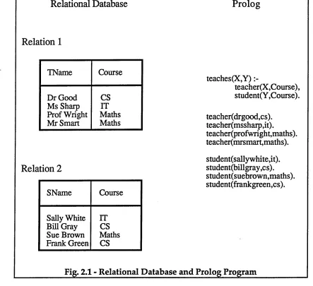
Relational Database Prolog
Relation 1
TName Course
Dr Good Ms Sharp Prof Wright Mr Smart
CS IT Maths Maths
Relation 2
SName Course
Sally White IT Bill Gray CS Sue Brown Maths Frank Green CS
teaches(X,Y)
teacher(X,Course), student(Y,Course).
[image:36.612.59.502.48.453.2]teacher(drgood,cs). teacher(mssharp,it). teacher(profwright,maths). teacher(mrsmart,maths). student(sallywhite,it). student(billgray,cs). student(suebrown,maths). student(frankgreen,cs).
Fig. 2,1 - Relational Database and Prolog Program
v r m i / i 't 'i x w i /
2.2.2. Logic Programming
Logic programming has evolved from theoretical work on automated theorem proving [Lloyd 84]. The previous section has referred to the use of predicate logic clauses as a means of knowledge representation. This model meets the basic requirements for a knowledge representation formalism in that it provides an unambiguous interpretation, allows the system to be reasoned about and facilitates communication between users. The problem in the use of predicate logic as an executable language is that application of a deductive method is liable to produce an extremely large number of deductions which although valid are not useful to the user; in other words the search space is uncontrollably large. The work by Robinson defining the resolution principle provided the means of controlling this situation and made possible the efficient automation of deduction [Robinson 65]. By restricting the knowledge representation language to Horn clauses, an interpreter could be produced which was not only sound but computationally efficient. The work of Colmerauer and Kowalski led to the development of the logic programming language Prolog [Colmerauer 73] [Kowalski 74]. This language is now widely used and familiarity with it is assumed [Clocksin 81].
The crucial feature that emerged from Kowalski's work was that clauses written in Horn clause logic have both a declarative and a procedural interpretation [Kowalski 74]. The declarative interpretation of a logic program rests with its definition as a clause set and specifies the relationship that exists between the head (left hand side) and body (right hand side) of the rule. The same logic program can be given a procedural interpretation which defines the operational semantics of the language. A clause can be regarded as a program and subclauses as procedures. Program execution involves the calling of appropriate procedures for each subgoal. Thus resolution can be defined in algorithmic terms using the procedural semantics of a conventional programming language. If the query
(contains europe, X). is put to the following program or clause set: partof(europe, britain).
partof(britain, london). partof(europe, france). partof(france, paris). contains(X,X).
1 u/u
contains(europe.X) ans(x)
ans(europe) paitof(europe,Y) V contains (Y,X),
\a n s(X )
contains(britain,X),
ans(X) contains(france,X),ans(X)
ans(britain) ans(fiance) partof(britain,X),
contains (Z,X), ans(X)
partof(france,Z), contains (Z,X), ans(X)
contains (london,X),
ans(X) contains (paris, X), ans(X)
partof(london,W), * ans(paris)
contains(W,X),
ans(london) partof(paris,W),
con tains (W^X),
ans(X) ans(X)
_________________ Fig. 2.2 - Resolution Search Tree__________________
the resulting resolution search tree is shown in Fig.2.2 (adapted from [Warren 88b]). Branching in the search tree occurs when alternative predicate definitions are present. Each node in the resolution search tree can be regarded as defining a procedure calling operation: the appropriate subgoal (in the case of Prolog the left hand one) is selected as the next call, the procedure whose name matches the call is invoked and the formal and actual parameters are unified. The body of this new procedure replaces the call in the goal list with appropriate unifiers applied, thus producing a new goal list. This method of handling literals in a clause as procedure calls allows a logic language program to be executed in a similar manner to a conventional imperative program. Where no alternative definitions of predicates exist the flow of computation is directly comparable to that produced in an imperative language.
However alternatives within logic languages have to be handled in a different manner because it may be necessary to "backtrack" to a previous
-15-state of the computation. This is known as "non determinism": at a general level Hogger defines a non deterministic program as one which "admits more than one computation, that is, has a branched computation tree" [Hogger 84]. However this feature of non determinism in logic languages is somewhat different from the situation that exists in conventional procedural languages. Although the flow of computation in an imperative language can exhibit branch or choice points, eg
if (condition) {do actionl} else
{do action2}
the branch representing the unsatisfied condition is always discarded, and there is never a need to maintain information about the computational state of an branch which has not been selected. In logic languages backtracking to explore previously marked choice points is the method by which the search tree is explored and the implementation of logic languages has to involve the storage of information relating to these branching points. This is discussed in Chapter 2.2.6 in relation to the implementation of Prolog.
It is the procedural interpretation that allows an automated system to be written to execute the language, ie to make the refutation proof [Lloyd 84]. The methods by which the execution of logic language systems is implemented are considered in Chapter 2.2.6. It is important to note that the use of a logic programming language allows rules and data to be represented in the same formalism and the inferencing mechanism handles both aspects in a uniform manner. This makes the use of logic programming languages for representing knowledge attractive.
2.2.3. Deductive Databases
have been reviewed by Gallaire and Minker [Gallaire 78], [Gallaire 84], [Minker 88].
From a formal viewpoint a database can be viewed in two ways; the model theoretic and the proof theoretic viewpoint [Gallaire 84], [Gardarin 89]. From the simpler viewpoint the relational database is considered to be a model of a first order logic. Thus a predicate name in a first order logic formula corresponds to a relation name. The values in the database are the set of constants satisfying the formulae and queries are treated as expressions whose truth value can be ascertained with respect to the database. However this view does not allow for inferencing techniques to be included into relational database theory and therefore a second approach to the database is defined as the "proof theoretic". In this view the database is seen as a set of logic formulae that can be used for inferring new formulae, ie as a set of axioms of a first order logic. In the proof theoretic approach the theory requires additional general axioms to be included concerning domain closure, completeness, unique names etc. Having defined the database in terms of the general and specific axioms, a general proof mechanism, such as resolution, can be used; this provides the formal interpretation of a deductive database.
Relation 1
TName Course
Dr Good Ms Sharp Prof Wright Mr Smart
CS IT Maths Maths
Relation 2
SName Course
Sally White Bill Gray Sue Brown Frank Green
IT CS Maths CS
Relation 3
TName SName Course
Dr Good Dr Good . Ms Sharp Prof Wright Mr Smart
Bill Gray Frank Green Sally White Sue Brown Sue Brown
CS CS rr Maths Maths
Fig. 2.3 - Relational Database with Derived Relation
by performing a Join operation, ie by combining Relationl and Relation2 with respect to the value of their common attribute "course". This is expressed as
MiL/t'L*/ X iVi/
However languages (such as SQL) derived from relational algebra or calculus cannot handle the inclusion of rules which are needed in a deductive database system, and thus designers of these systems have looked towards the logic languages as providing suitable rule definition and query answering facilities [Maher 88]. The concept of Datalog programs and their use in deductive databases is looked at in the next section (Chapter 2.2.4).
The implementation of a deductive database system can take a number of different approaches. The degree to which the inferencing system is integrated with data management can vary from "loose coupling" to "full integration" [Gardarin 89]. A fully integrated system implies that there is no separation between the inferencing mechanism and the data storage management; they are integrated together at a low level of system implementation. The actual database management system is designed in such a manner as to include the rule base management and the logic interpreter to handle queries; the languages which handle rule and data manipulation and querying are likely to use a common syntax, and the user is presented with an integrated interface to the system. "Coupled" systems use a conventional database management system as the underlying storage and manipulation mechanism, and the inferencing component is "bolted" onto this. In a loosely coupled system the inferencing mechanism is likely to represent rules in a different language from that used to define and handle the data, whereas tighter coupling implies that rules and data are expressed in the same formalism, and the storage management is hidden from the user. Fig.2.4 which has been adapted from [Gardarin 98] gives a schematic representation of these three approaches.
An example of the tightly coupled type of system is the Prolog/PSAlgol system where rules and data are expressed in Prolog but the underlying storage mechanism for the Prolog "facts" is a database management system [Moffat 86], [Gray 87a]. Work on a Prolog database system at Edinburgh is concentrating on the organisation of Prolog modules and files for disk storage in order to implement a fully integrated deductive database system [Williams 87a].
However because of its "non" logical features Prolog does not provide a formal model for a system definition and manipulation language for deductive databases, and this has led to the concept of Datalog programs. These are discussed in the next section.
-Prolog or DBMS Calls
I
Prolog Interpreter
I
DBMSI
(a) Loose Coupling
Prolog or Datalog
1
Deductive Component
DBMS
(b) Tight Coupling
Data Manipulation Language
I
Rule Definition Language
1
Language Compiler
Extended Relational Algebra
Memory
Manager BuffersDBMS
i
---r - w .
2.2.4. Datalog Programs
Datalog programs can be used to provide a formal system definition and a query language: they specify the database in terms of Horn clauses without functions symbols, ie they can be regarded as Horn clause logic programs with no extra logical features, functions or negation [Minker 88]. Thus the semantics for a Datalog program can be regarded as having a declarative or procedural interpretation in the same manner as generalised logic programming [Kale 88a].
Several extensions to the concept of Datalog programs have been put forward in order to enhance their usefulness as a database definition formalism. These include the incorporation of negation: negated predicates are allowed in the rule body. In order to allow a unique "least model", a program which includes negation has to be stratified; the program is divided up into levels or strata, and predicates can only be negated if they have been fully defined in one of the previous strata [Gardarin 89]. Similar extensions may be provided for the inclusion of functions and set operations.
Datalog programs can be defined using a specific syntax for a particular database system, or by employing a subset of a logic language such as Prolog or the Pure Logic Language. They allow the system designer to express both the intensional and extensional database in the same language, the complete program defining a "logic database" [Gardarin 89]. The first benchmark program with its associated queries given in Appendix C is an example of a Datalog program written in the Pure Logic Language.
2.2.5. Implementation of Logic Based Knowledge Bases
As has been seen the concept of a knowledge based system includes not only the storage of data but a reasoning component and thus the question of efficient implementation of such a system has to address both aspects. As this project is primarily concerned with the use of logic languages as a knowledge representation method the discussion to follow will concentrate on systems using this type of model.
In general the inclusion of an inferencing mechanism puts heavy computational demands on a system because the algorithms used to implement it define the testing of many different hypothesis. These tests
-^•1 Hf'pi'V'f X W
usually involve a series of pattern matching operations, the results of which are discarded if the match fails. In this way systems with deductive capacity generate a search space for each query and the effective management of the search process determines the performance of the system [Charniak 85]. It has been shown that the search space for logic programs can be reduced by the application of theoretical concepts such as an SLD resolution based refutation proof (see Fig.2.2 for an example of a small resolution search tree). Helpful as this is, for a logic based program which includes a considerable number of alternative definitions, query response is still going to involve computational operations whose results do not contribute directly to the answer.
The question of implementing efficient methods for handling the heavy computational demands of these systems can be tackled in three general ways:
a) the use of parallel hardware to allow the simultaneous execution of different computations,
b) the development of separate methods for implementing the inferencing component and the data management aspect,
c) the introduction of special compiler techniques to produce efficient "tailor made" sequential code for each inferencing procedure in a given program. This is looked at in more detail in Chapter 2.2.6.
It is important to note that these three approaches are not mutually exclusive and many systems based on parallel architectures involve aspects from categories b) and c). The question of parallelism in systems based on logic languages is looked at in detail in Chapter 2.3 and Chapter 3.
^napier 1 wo
transformations have been made in order to cut down the overheads involved in recursion [Bancilhon 86], [Valduriez 86], [Ramakrishnan 88].
The question of data handling involves not only the conceptual level aspects of representation and relationships but inevitably the method of disk storage and retrieval. Indexing schemes such as that proposed for deductive databases by Lloyd [Lloyd 81] are included here. Another approach is the design of specialised hardware which aims to give rapid access to appropriate disk stored data: this includes systems such as CAFS [Howarth 85]. In order to meet the disk retrieval demands of knowledge based systems there has been considerable work on a number of different hardware systems which can be regarded as "backend" machines offering fast associative access to data. The paper by Gray gives a summary of work on these systems in Britain [Gray 87b]. It is outside the scope of this project to give detailed consideration to methods, which may involve hardware and/or indexing schemes, for handling secondary storage data, but it is recognised that this area is of great importance in the implementation of realistically large knowledge based systems.
2.2.6. Implementation of Prolog
In Chapter 2.2.2 an outline description of the procedural interpretation of resolution based logic languages such as Prolog was given. This section looks at this in more detail and specifically how the system can implemented in a compiled version.
There are two components which implement the procedural semantics for a logic language such as Prolog: first the choice of which procedure is to be the next candidate for execution is determined by the "call selection" or "computation" rule. The second component of the interpreter is a matching or "unification" procedure which is invoked each time a goal or subgoal is selected. The unification procedure is responsible for determining whether a call to a subgoal succeeds or fails, and in the case of success may produce binding values for uninstantiated variables [Lloyd 84].
The standard computation rule used by Prolog to implement the resolution proof always selects the first call in the goal, replacing it with the body of the new procedure [Hogger 84]; this leads to a depth first exploration of the search tree. When alternatives are encountered and branching occurs,
-y ~ r i u p t a i w u
the branch points are stored by the system as backtrack points, ie the place at which the computation must resume in the event of failure of a branch or if a full set of bindings is required.
From this brief description of the execution process in a Prolog program it can be seen that the internal state of the computation at any given time can be represented by the current position relative to the search tree. Branches that have been explored can be discarded, those that have still to be explored must be stored as choice or backtrack points, and the present state of the computation or the "environment" is represented by a goal list plus any current variable bindings. The ability to return to a backtrack point and pick up the computation from that point can only occur if the environment that existed at that point is also stored. Thus the information required for backtracking involves the storage of previous bindings and goal lists.
An interpreted Prolog system includes data structures to represent the original clauses or program, the present state of the computation including current variable bindings and information on previous environments to allow backtracking to occur where appropriate. The execution of the program will be driven by generalised algorithms implementing the call selection or computation rule, and the unification operation.
However the use of these generalised algorithms applied at run time will often involve unnecessary computations. Most recent implementations of Prolog have abandoned the use of general computation and unification algorithms in favour of a compiled system. At program insertion time each procedure, ie each group of clauses defining a predicate, is compiled into low level code which specialises the unification and computation rules for that procedure. This low level code replaces the original program and there is no need for the general interpreter code to be held in the system. At run time the compiled code which has specialised the deductive process for each goal call is used at run time and results in substantial savings in terms of unnecessary computations.
l u/li
Prolog Rule:
concatenate^], L, L).
concatentate([XILl], L2, [XIL3]) :- concatenate(Ll, L2, L3).
WAM Code for rule: concatenate/3:
switch_on_term Cl a, Cl, C2, fail. Cla:
Cl : try_me_else C2aget_constant nil, A1 get value A2, A3 proceed
% concatenate( % [],
% L, L
%). C2a:
C2 : trust_meget_list A1
unify_variable X4 unify_variable A1 get _list A3 unify_value X4 unify_variable A3 execute concatentate/3 % concatenate( % [ % XI
% LI], L2,
% [
% XI
% L3])
:-% concatenate(Ll, L2, L3).
Fig. 2.5 - Compiled Prolog Code
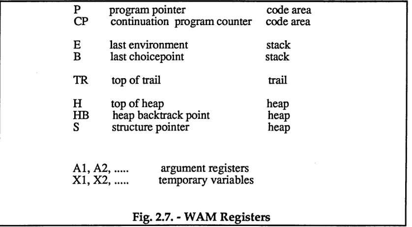
various stacks and registers to hold control data such as backtrack or choice points. The performance benefits are further enhanced by the incorporation of indexing methods for access to base predicates. The use of the Warren Abstract Machine has also been employed in many parallel Prolog systems and it has set the standard for the implementation of high performance sequential Prolog systems such as Quintus Prolog and BIM Prolog .
Fig. 2.5 shows the WAM instructions produced by the Prolog compiler for the rule for list concatenation: these are included as an example of the intermediate code, ie the generalised machine instructions which can then be translated into the native machine code of the target machine [Warren 88b]. Programs can either be stored as WAM (ie intermediate) code or specific machine code.
It is worth looking in outline at the WAM data structures that are used to control the program execution. Many parallel logic programming languages are based on these data structures and the implementation of the Pure Logic Language which is discussed in Chapter 4 shows some similarities.