WW®
'Mia
EUR 3141.e
mm
ÉÄriSB
E U R O P E A N A T O M I C E N E R G Y C O M M U N I T Y - E U R A T O M
^5i^s¡LMf^i*íÍÍÍ^^
É
ΙΐΙΚίΒ
- H Wil,
PLUTHARCO
A PLutonium, Uranium, THorium Assembly Reactivity
i"
r í t Í ^ ' ^
*Í*^^^ft
^Í^K^JJ1 Jr^mnir t^B^f^J^I^^jP^
ut ■ 'ï I '
\Ψ
*
M
»1
m-w
« I I I
i
¡pf ji®i!s»ISlli
!
[4
■Sr *wS
:5lirø^
:rø
;t¿ I t H
$Hïi
aiti
up
ΜΚ.;'ί
A t
«1'i».·«
I j · I p ^ l l LEGAL NOTICE
iii»
rikt- TfiaW *FBi*V' »^ 'ï ï*1 eWïl'.Li ■. ^ Μ1' ι τ 43*! '·]JH'irlü! 'iHffi1 <'{ )fl '18210'';
This document was prepared under the sponsorship of the Commission of the European Atomic Energy Community
É W M P K
(EURATOM).
Wijt"
Neither the EURATOM Commission, its contractors
person acting on their behalf : nor any
Make any warranty or representation, express or implied, with respect to the accuracy, completeness, or usefulness of the or that the use of any process disclosed in this f (»3Íai!$&2ÍÍlffl vJm* document may not infringe privately owned rights ; or
Assume any liability with respect to the use of, or for damages resulting from the use of any information, apparatus, method or process disclosed in this document.
ψ
m a n e oil y WÎUXÎUII>^ υχ i q j i e s e u i a u u i i , crespect to the accuracy, completeness, -¡ l% ^ w l Í l í ' l ¿ K p ^ ^ h i information contained in this document,
information, apparatus, method, or p r document may not infringe privately owi
Israel«
This report is on sale at the addresses listed on cover page 4
at the price of F F 17.50 FB 175 DM 14.— Lit. 2180 Fl. 12.65
When ordering, please quote the EUR number and the ti which are indicated on the cover of each report.
iliiinffi
This document was reproduced on the basis of the best available copy.
» f e w » '
1 1'
vi$Mij
EUR 3141.e
PLUTHARCO, A PLutonium, Uranium, THorium Assembly Reactivity COde — Physical Concepts, Comparisons with Experiments and Code Description by W. DE HAAN and R. MEELHUYSEN
European Atomic Energy Community — EURATOM
Joint Nuclear Research Center — Ispra Establishment (Italy) Reactor Physics Department — Reactor Theory and Analysis Brussels, November 1966 — 128 Pages — FB 175
In the framework of the ORGEL reactor physics development pro-gram, a new method for heavy water lattice calculations has been esta-blished.
This method is intended for design survey type calculations and for preliminary fuel cycle analysis.
EUR 3141.e
PLUTHARCO, A PLutonium, Uranium, THorium Assembly Reactivity COde — Physical Concepts, Comparisons with Experiments and Code Description by W. DE HAAN and R. MEELHUYSEN
European Atomic Energy Community — EURATOM
Joint Nuclear Research Center — Ispra Establishment (Italy) Reactor Physics Department — Reactor Theory and Analysis Brussels, November 1966 — 128 Pages — FB 175
In the framework of the ORGEL reactor physics development pro-gram, a new method for heavy water lattice calculations has been esta-blished.
Lattices fueled with uranium, thorium and plutonium can be investi-gated. The method is based on the four factor formula, the two group theory and the Westcott cross-section formalism.
The method has been written in Fortran II for the IBM-7090 com-puter, with the name PLUTHARCO (PLutonium, Uranium, THorium Assembly Reactivity COde). The code gives directly with the results the input data for RLT-4 burn-up calculations.
Lattices fueled with uranium, thorium and plutonium can be investi-gated. The method is based on the four factor formula, the two group theory and the Westcott cross-section formalism.
EUR 3141.e
EUROPEAN ATOMIC ENERGY COMMUNITY - EURATOM
PLUTHARCO,
A PLutonium, Uranium, THorium Assembly Reactivity COde
Physical Concepts, Comparisons with Experiments and Code Description
by
W. DE HAAN and R. MEELHUYSEN
1966
C O N T E N T S
Introduction 2
Section I
k
1.1 The thermal multiplication factor
1.2 The fast fission factor
1.3 The resonance escape probability
1.4 The thermal utilisation factor
1.5 Average to uranium thermal flux ratio
1.6 The diffusion area
1.7 The thermal diffusion coefficient
1.8 The slowing down area
1.9 Fast diffusion coefficient
1.10 Lethargy range
1.11 The initial conversion ratio
1.12 The infinite multiplication factor and buckling
1.13 Two group diffusion constants
Section II - Comparison with experimental results 26
11.1 EXPO experiments
11.2 CISE experiments
11.3 Savannah River experiments
11.4 Chalk River experiments
11.5 Conclusions
F i g u r e s
S e c t i o n I I I - C o m p i l a t i o n of f o r m u l a e 45
111.1 Cross sections
111.2 Physical parameters
III.
t)
Geometrical parameters
Section IV - List of Tables 07
Section V - PLUTHARCO, Directions for use 106
V.1 Input
V.2 Card formats
V.3 List of entries for PLUTHARCO
V.4 Output
V . 5 Example of o u t p u t
R e f e r e n c e s m
SUMMARY
In the framework of the ORGEL reactor physics development pro-gram, a new method for heavy water lattice calculations has been esta-blished.
This method is intended for design survey type calculations and for preliminary fuel cycle analysis.
Lattices fueled with uranium, thorium and plutonium can be investi-gated. The method is based on the four factor formula, the two group theory and the Westcott cross-section formalism.
3
-Introduction (*)
Since 1961 at Euratom a method is in use to calculate the physical constants of an ORGEL reactor lattice cell.
This method has been programmed under the name of CAROLINE I for the IBM 7090 and it has been found to be well adapted especially for survey and optimation calculations. However with the use a great number of shortcomings have been found giving rise to the necessity of an improvement and a greater serviceableness. A modification of the program has been done, called CAROLINE 1 M,
At first the program has been recoded such, that only the differences with respect to the former calculation have to be introduced, de-creasing significantly the number of input cards.
Secondly new geometries hare been added together with an increased choise of coolants. Furthermore an entry has been left open to introduce special materials in any of the compounds, like fuel, canning, filler, pressure tube, calandria tube. Only the modera-tor has to be a mixture of heavy water.
The physical scheme however was not changed. The recent interest in Thorium fuelled reactors showed the necessity to have again an easy to use method to study the possibilities of this fertile material together with U233, U235 or eventually Plutonium.
For this reason the existing code CAROLINE 1 M was modified again.
The geometrical part has remained as formerly but adaption to any general fuel composed of any U, Pu, or Th isotope made it necessary to change completely the physical base, from the correlational type to the straight-on physical type. For this reason it was decided not longer to speak about a member of the CAROLINE family, but give to the code a new name, PLUTHARCO,
It is realised, that this description, though fairly acceptable, is only a raw scheme. It should however be remembered, that the purpose of such a scheme is to allow the fast execution of rea-sonably reliable survey calculations often involving the variation
- k
-of an appreciable number -of parameters. For this reason the recipe must be fairly simply. In later stages where more accuracy is needed, these calculations should be compared with more refined schemes present at Euratom (Ref. 25 )·
Results of this scheme have been compared with measurements and are shown in another section of the paper. The agreement in general is quite reasonable.
The report is divided into sections being
I. The general description of the theory with the references II. Comparison with experiments
5
Section I
1.1. The thermal multiplication factor
The thermal multiplication factor η is defined as the number of fast neutrons produced per neutron absorbed in the fuel.
As this may be diluted with oxygen carbon and other materials, their cross sections have to be taken into account in *|
It may thus be written as
ï
--n
(*Zff)*
S v(i) Σ*CO
2¿
$ U ¡ ) * N d V d
ι
where ί is one of the 8 isotopes being present in the fuel mixture
V(i) is the mean number of fast neutrons born per absorption of a neutron in a fissionable nucleus
2f(') is the fission cross section of each of the isotopes being present in the fuel mixture
5Λ(Ό the absorption cross section of each of the isotopes
being present in the fuel mixture
Σα^ "the absorption cross section of the H, diluent atoms per atom of fuel mixture.
The cross sectionsare the mean over the fuel spectrum. These spectrum effects are calculated assuming the Westcott conventions (Ref.l), i.e. the spectrum may be supposed to be built up of a Maxwellian and a l/E tail characterised by the parameters Τ and r .
The method to calculate r is outlined in Ref.2 and 3.
The spectrum mean cross sections are then found from the formula
/ I . T ;
6
-in which % is the 2200 m/sec cross section
g , s Westcott's constants
<r the equivalent 2200 m/sec cross section averaged
over the above defined spectrum
0" the mean cross section of neutrons with spectral
constant Τ over the above defined spectrum
T. = 293,6° Κ
For elements having resonances at low energies (Pu239, Pu240) s is
replaced by s' (Ref.2) where
■>/
ƒ
s: - S. / / 4. + Ar. 1 . Ν ·
%K
with V/Seff being the mean chord length in the fuel element I the resonance integral
N. the number density of atoms of species i in the fuel element.
In fact the former formula represents the assumptions of the N.R.I.Ml approximation. For isotopes being present in large concentrations U238, Th232 the Westcott scheme is not usable any more, and the three values have been set zero. The resonance absorption due to these materials is calculated taking into account the self shielding of the resonances and not by taking the infinite dilution as is assumed in Westcotts treatment. Also for the structural materials s is set to zero, i.e. supposing them to be pure l/v absorbers.
Having once the mean spectrum microscopic cross sections; the mean fuel cross section for fission, °f(fuet) an^L absorption °i^ue()
may be written as»
■KM) " ?
w f(i)where S is the summation over i terms (i = 1,8)
í
°"(>) the cross section of the ith isotope
•v.') the density fractions of the ith fuel or fertile isotope Nd the number of diluent atoms per atom of fuel and fertile
material (i.e. for U 0? is 2)
7
The macroscopic fuel cross section is now simply found from
fuel - "'fuel
Σ*_ . J*Ü
*.
Mfuel
where fuel is the mean fuel cross section over the Maxwellian + l/E spectrum for the fuel composition as defined in input ' fuel is the density of the fuel compound in gr/cm
fuel is the molecular weight of the fuel mixture A is Avogadro's constant.
To calculate the microscopic cross sections the spectral constants have to be known.
Very often however f. i. in the case of Plutonium isotopes they cannot be defined properly.
For this reason a switch has been built into the progpam giving a choice of 3 different methods as given in the next table.
Choice input 20 Description
1 1 Candu correlated spectral
constants
2 0 Spectral constants to be
provided by the user
3 1 Input of TERMIDOR parameters
Choice 1
Canadians have (Ref.5) measured the relative reactionrates Pu239/U235 and Lu/Μη in the fuel and moderator of a Candu lattice cell and analysed them to obtain the spectral eonstants of the Westcott formalism. Coolant channels containing different mixtures of light and heavy water at various temperatures were successively U3ed in the experiments.
As result an empirical formula has been derived to.calculate the spectral constants in fuel and moderator for lattices with similar geometry.
8
-V
T« + *»·<■
+ b, ( ^
a) * K ( v ^
6)
+
W**\{?.-\)
♦ K C ^ s U v O * b
c(vz
s)
c(T
c-T
m)
T^ ^ T „ v î o o r
with r is the relative epithermal weight of the neutron spectrum Τ physical temperature
T' spectral constant
m.f.t.c moderator, fuel, tubes and coolant respectively b variables obtained from fit with experiments
a,s absorption, resp. scattering labels to macroscopic cross sections.
When no region subscripts are attached to the parameters V 2S , the
mean over the fuel bundle is meant.
Apart from these two most important spectral constants one needs the same for the tubes and outer coolant region. These were calculated supposing that in these regions the spectral constants were the mean of the former two.
Choice 2
Spectral constants are provided by the user.
Choice 3
TERMIDOR parameters input (Ref.6)
Giving the characteristics of a simplified lattice, the TERMIDOR oode calculates the macroscopic cross sections of some important not l/v (U235> Pu239) absorbers together with the l/v cross sections
(per unit cross section at 2200 m/sec) averaged over a neutron spectrum calculated by the code (f l/v).
9
-The calculation of this spectral constant is done by the formula
Τ = τ T0
* fi
ν
a formula on its turn derived from
f.
F< -
ΓΓΪ.
ν V 4 Τ
Although the not l/v cross sections (as said before) are entered directly, the code writes the spectral constants in the output for every isotope (thus included the not l/v ones).
Two iterations are made in every calculation. At the first iteration the value of r is taken to be zero. With this assumption a complete calculation is made until the lattice buckling. From these data
another value of r is calculated. After entering this value in the Westcott formalism the microscopic cross sections are corrected and another buckling calculation performed.
The cross section values are given in tables". Except the first method of calculations the fuel microscopic and macroscopic cross sections the program accepts directly the num~-erical values of the macroscopic cross section¡3 by the so called "7 choice" (see: Directions for use).
y
10
-1.2.. The fast fission factor
The calculation of the fast fission factor ε is based on the method of Fleishman and Soodak (Ref.7)5 however the scheme was simplified to a two group structure instead of a 3 group one. The main reason of this simplification is the uncertainty of the inelastically slowed down spectrum. This is supposed to be described by the function
-E η(E) = E e
The form of this spectrum however is very similar to the fission
spectrum of the region below 1 MeV, so that the division into 3 groups of different spectra was felt to be a little bit to luxuous. Although the scheme remained unchanged, the cross sections of the two groups until 1 MeV were taken equal.
The groups are separated by the fission thres-hold. The region in which fast fission appears is defined as the region surrounded by a rubberband strung around the fuel element. The fission source is supposed to be flat as well as the sources of the neutrons of the next generations. In the first group neutrons are able to give fission, capture and scatter elastically and inelastically.
In the second group fission is not permitted as well as inelastic scattering.
Atoms with fissionning capacity beneath the U238 fission thres-hold are corrected for the fact that sub-thres-hold fissionning is not permitted, i.e. the fast fission in the second group is normalized
and added to the first.
The microscopic group cross seotions are calculated from data of Ref.8 by contraction of 3 groups to the epifission thres-hold group and 6 groups to the subfission thres hold group.
11
t·1 u i.k t r
o- - S F o- m S f (<r , S o- ")
V
fl-tr «
I » l M ï * !
<T S f <Γ
c.I k I.k c.lc
Xi
' S f ^ + S f V W2. S i (v<r) + S f (*<r). . We
M le I.k v * \ j I.j ^ f,J 2
t·1 i *.j *.J
tr . - S f . <r .
C.I ; » j C.j
σ - S f <Γ. « cr _
α-with the notations: k is the group index for the calculation of cross sections of broad (epithreshold) group I of the two group scheme
12
f , F are the fractions of fast neutrons r.w ij
born in fine group k resp, j per neutron born in any of the two broad groups I and II
W is the number of neutrons born in group two per neutron born in group one after a fission of ä fuel nucleus. It is thus the ratio of the fission spectrum
integrals above and beneath the fission threshold of U238, ( v r ) the number of fast neutrons generated per neutron absorbed
in fast group j . The subscripts:
t = total
I*II = (inelastic) scattering from group I to II I » I = (elastic) scattering from group I to I
c= capture f = fission s = scattering
n,n',k= inelastic scattering out of fine group k k,k'= scattering from group k into group k'.
The calculation of the mean macroscopic cross sections is done in two step3:
1. The calculation of the macroscopic cross sections of the different materials by
1
-
—
( »Vi* V
2 +)
M where again
Ρ = density of the compound material A ■ Avogadro's number
M = molecular weight of the compound
N, ,N„ = the number of atoms 1, 2 ... per molecule of the compound.
The calculation of the homogenized macroscopic cross sections by weigh ing the material cross sections with their respective volume fractions.
13
The mean cross sections are calculated for all of the following
interactions:
2
t I= the total mean macroscopic cross sections in group I
2
l_
v.
1= scattering mean macroscopic cross section in group I
2
τ-π
= the mean macroscopic transfer cross section out of group I
5fi
= the mean macroscopic fission cross section of group I
tZf
t= the mean fission source density per unit of flux . second
in group I
l
cl= is the mean macroscopic capture cross section in group I
2x
.
■ the mean macroscopic total cross section in group II
2
χ
= the mean macroscopic capture cross section in group II
2
4>i
= the mean macroscopic scattering cross section in group II
The number of collisions in group i , C¡ per original fast
neutron can now be written:
C ι
• 661 T> ( of t Zt l)
C
I
0 -
ν(ο*ΚΛ
( ο·
5 β 1: ÜgalissLJ )
ο.Λ39 p ( o
ez
t > I) ( l * £ ^ £ i t - ) ♦
*(*·*■* J
· c
x. l i ^ î
< -
PO B
Σ*.ι)
**·*
2*ΛThe extra number of fast neutrons generated per original fast
neutron ( ε l) is then the product of the collision probabi
lities and neutron gain per collision summed over the two groups
or:
e - i
= c e
+ C G
I I
π ι
where:
G Χ
G*
* zf.ι 2f,i 2c.i
*t.I
-
\k
-1.3. The resonance escape probability
The calculation of the resonance escape probability may be devided into the following parts.
1. The effective surface per gram of fuel
For the fuel element the effective surface per gram is calculated by the method of Hellstrand (Ref.9). This means, that the fuel element is replaced by a rod with external surface equal to the rubber band surface (strung around the bare rods). The inside moderator holes are supposed to be a number of circular cylinders whose radii r are those of the inscribed circles of the holes.
The surface generated by this cylinders however has an efficiency given by the formula
V » 2 Z'r (< P0(Z'r) )
where
Σ being the mean volume weighed scattering cross section of the canning, organic and filler present in the holes of the cluster, which on its turn derived from
L ■ Σ'ν (ιΡ
β)
A
This relation is derived in Ref .10 for cylindrised as well as cluster cases.
This recipe is easily usable in all regular lattices because in all these cases the holes are of cylindrical square or triangular shape.
For the 22 rod cluster, where the holes are irregular, the effective radius of the inscribed circle was calculated as follews.
The volume of the moderator inside the rubber band strung around the cluster was divided by the number of holes, to obtain the mean volume per hole.
I f t h i s hole was c i r c u l a r i t would have an i n t e r n a l r a d i u s
re
15
For an hexagonal arrangement one can show that the effective radius of the circular hole would be
I j-r*ß
t"T
with d = cluster pitch s = rod radius
In this case the inscribed circle would be
r.' d s
r . — s Vi
If it is supposed that the holes are hexagonal the inscribed radius might be written
r. „ r </<* ι β ·h'M ·—
Ρ
1
4 24 V
ν„
Γ»
1 . _ < *
βΓ,-ι
Τ «ί»(-Î)
The effective rod radius is found by the relation
2 2 ir S2 = Vf u e |
when V„ is fuel volume, fuel
2. Calculation of the resonance integral
The cluster is now identified with an effective rod with the same surface per gram. For this rod the resonance integral can be looked-up in a table.
These tables were prepared formerly by calculating for uranium and thorium compound (metal, dioxide, mono and dicarbide) the resonance
16
The results were fitted for temperatures between 20 and 1600 C an
I = A + Β /I
For any temperature the values of A and Β can now be interpolated giving rise to its proper resonance integral,(see table l ) .
For fuels composed of more than one fertile material, the resonance integral of each material is obtained first and the density weighed mean value calculated afterwards, i.e. with the assumption that the resonances of the different materials do not interior with each other.
3. Calculation of resonance escape probability
Being known now the slowing down cross section ξ Σ5 of the lattice,
the resonance escape probability can be calculated by
«ZsVv.
where Ν « number of atoms of the absorber per unit volume V ■ volume
ft = the flux ratio at the resonanoe energy between fuel and moderator
f » fuel m » moderator
The factor f> is the product of two terms:
the first one ( <** ) is due to the non uniformity of the fast sources. As a consequence of this fact, at large pitches, the slowing down distri bution of the neutrons in the cell is not flat, ω is calculated as in CAROLINE (Ref. 26 )f simply by assuming age theory to be valid and by
calculating the energyspace distribution in a bath of heavy water for a linear source (neglecting the presenoe of the fuel rod)}
the second one ( ï ) due to the depression in one resonanoe occurred from the neutron absorption at higher resonances and, for the lowest resonances, to the faot that the NRapproximation in the moderator is not anymore valid.
17
χ
tCr Τ°
^ «
(Λ♦ i c V V
12
Ι, (tri
Ν
»
y
where
"v.
is the reciprocal slowing down length at resonance
energies and
rthe effective fuel rod radius.
K.
is calculated from
*c
z.
l i h .
. z
trCt
o e*
2'
/ A U)
ξ Z
sbeing the mean volume weighed slowing down cross section of
the fuel, canning, organic and filler present in the homogenized
cluster.
2
trthe volume weighed mean transport cross section of
the former four materials.
The choice of Au
is somewhat arbitrary. Different authors propose
values between 3 and 7 lethargy units. Therefore a mean value of 5
lethargy units has been chosen and it was found that with this figure
good results were obtained by comparison with different experiments.
1.4. The thermal utilisation factor
For the calculation of the thermal utilisation factor, defined as the
number of neutrons absorbed in the fuel per neutron absorber in the
total lattice cell, the lattice cell is approximated by a cylindrical
homogeneous fuel assembly at the center being surrounded by five
cylindrical regions, i.e.
1. the outer coolant region
2. the pressure tube region
3. the insulation region
4. the calandria tube region
5. the moderator region.
Having once decided this, the calculation of f can be divided into
two parts
1Ö
with F equal to
f
· S o ·
fcc
Because the cluster is composed of four materials being fuel (f), canning (g), filler (r) and coolant (θ) the factor f can be written as the ratio of the reaction rates in fuel and cluster or
S being the sum of the former four components of the fuel rod. Once the volumes and cross sections are known the only factors to be found are the relative fluxes.
These now are calculated from an expression suggested by Amouyal and Benoist (Ref.12), giving the ratio of the flux at the fuel rod periphery to the mean flux in the rod.
In the program is supposed that canning, filler and coolant are exposed to the same flux being the one at the periphery. The expression then writes
*. ■ f
2
-
·*!
Α
['"Ίί-Γ&Π
where the subscripts c, s and t mean capture scattering and total respectively and A, <*. and β are functions of a . 2t the
pin radius in units of total mean free paths (Table 2 ) ,
The cluster to cell utilisation factor is calculated by the method of Amouyal, Benoist and Gfuionnet (Ref. 13). In this method the lattice cell has to be divided into a number of cylindrical regions (see description before) making the following hypotheses
1. the angular neutron density at the different surfaces is isotropic 2, the collision densities for the second order and multiple collisions
are supposed to be independent of the place in the region.
19
Once these are known, the currents in out and inward directions
can be found for every boundary. This gives rise to a set of two
current equations for every region which may be solved by matrix
calculus.
The currents on their turn give the absorption fraction in every
region from the consideration that:
absorption fraction in region i ·
source in region i net outscattering
from region i
total source in cell lattice
For the homogenized fuel region this absorption fraction is equal
to the former defined factor ?
cc.
The flux in every region can now easily be found from the equivalence
relation between sinks and sources in a region
N
*
eiV,?¡
F, S Qrt
9i
■ - * - . §
^
J * 1
i 'i
Furthermore the cell homogenized absorption cross section becomes
O " — M
S V cp
In these formulae
j
is the region index,
2
ay
tτγ
the macro
scopic absorption cross section, volume and flux respectively and
f¡
the absorption fraction in region i ,
1.5· Average to uranium thermal flux ratio
Once defined the cluster to uranium flux ratio and known the flux
in the six regions the fuel to mean lattice flux ratio can be easily
20
-<Pu. vf + ν^ + vr+ v0
The following symbols have been used: V = volume g = canning f = fuel o o coolant
r = filler
In the thermal energy group the cluster is supposed to be formed by a rubber band strung around the canned cluster. The volumes have to be calculated in agreement with this assumption.
1.6. The diffusion area
For the calculation of the diffusion area, La , the lattice cell
is supposed to be divided into two different regions, the central non-moderator region and the peripheral moderator region. It is furthermore supposed, that the absorption of the neutrons in the central region is totally due to the fuel so that
fc =f
and
4-f
where fc is the capture fraction of the central region
f the thermal utilisation factor for the lattice cell fin the capture fraction of the moderator.
Furthermore if the regions are thick one may write the diffusion area of the lattice (Ref,14) as:
L
2-
OL;
* ί . £
The diffusion area of both the central and the moderator region are found with
21
-For the central region however these data are derived with the formula
2. - Ϋ ^ «-ir - - :ν a n d' ^ ena 2 _ -a» v* 2
-i.e. for the absorption cross section the absorption of all the other materials in the central region is neglected with respect to the fuel absorption.
1,7. The thermal diffusion coefficient
Once known the cell absorption cross section and the diffusion area the lattice diffusion coefficient is given by
D = L2.Z0
1,8, The slowing down area
The insertion of a fuel element in a bath of heavy water influences on two different ways the Fermi-age :
1. by a change of the fast neutron spectrum
2. by a change of slowing down and transport properties,
1. The neutrons born in the fuel element have a definite probability to collide with the fuel to have an inelastic collision and the mode rator atoms (especially H) to collide elastically.
Both collisions decrease the neutron energy giving rise to a perturbed fission spectrum.
Defining the Fermi-age of heavy water for a fission spectrum,inelastic scattered spectrum and elastic scattering (by Η atoms) Τ, , t¡ and \
respectively, one may write the corrected value in the moderator by
22
with
T>
ubeing the probability of a fission neutron to collide with
an H atom in the fuel rod
pj
the probability of a fission neutron to collide inelastically
with an uranium atom in the fuel rod.
Assuming that inelastic scattering is only possible in group I of the
fast spectrum (see calculation of g ) and knowing the total collision
probability
C
, the value is easily calculated from
Ci
with
f resp, B
fuel and bundle respectively
Ζ
the inelastic fuel scattering cross section
Z
t,
the total fast cross section of the bundle
As elastic scattering to Η atoms is possible in both fast groups I and II
the formula
P
Hcan be written
P
C
ν°
Σι*ι,ο
+C
2*,x,n V»
*♦ ι
y»*t.i
V
e2
t/tIn the FleischmannSoodak scheme neutrons of group I only can scatter
out of the group or scatter with conservation of energy in the group.
For this reason the inelastic organic scattering cross seotion has
been used in group I, thus supposing that inelastic scattering is
only due to hydrogen.
In group II where all soattering is supposed to be with conservation
of energy only the hydrogen part has been taken, i.e. multiplying the
organic cross section with the fraction of the hydrogen scattering.
The Fermiages for the different fast spectra can be written as
follows
3supposing that the cross sections of the moderator are not
energy dependent over the whole energy range from fast to .025 ev
2
23
-\
-τ.
ι
Te ■
τ
rei
Ζ'Po V
42ο 1 —I - Q ΰυΛ
"Ρ
{~J
- *
Δυι
^ο (pi)* Q ( 4
-<* Λ ϋτ β *
With Q"1 . 3 (<*»)*, . (Zty),
and ι τ ι e Au » lu — » In —
To Eo
is the lethargy difference between neutrons of energy E and £0 .
For T, and T¡ the last term on the right side corrects the age values to spectral constants Τ .
In Te another unit of lethargy is subtracted to take into account
the elastic scattering due to the Η atoms.
For Tyes the same relation is used calculating the lethargy range
between neutron temperature and mean resonance energy which is supposed to be 30 eV.
The Fermiage to resonance energy in the moderator thus is the difference between the one over the total range and the range from thermal to resonance energy
Τ , X . AT res, m m tes
2. Supposing that after one collision in the moderator the neutrons have been diffused out perfectly, i.e. the fluxes in the lattice cell are space independent, one may use the theory of homogeneous mixtures (Ref.15) to obtain
24
-Assuming further that also in the cluster the slowing down and transport cross sections are energy independent one may correlate the lattice cell ages to the moderator ones by
τ'res χ = u*es,m
The mean lattice cell slowing down cross section parameter i.e. ξΣ5
is obtained by taking the mean over the different materials present in the lattice cell weighing every cross section with the respective material volume of the cell i.e. again assuming that the flux is spatially constant.
1.9. Fast diffusion coefficient
The lattice cell fast diffusion coefficient is then calculated by
Δυ
a formula obtained by assumptions already described in the former parts.
I.10, Lethargy range
The mean lethargy range travelledby the neutrons can easily be ob tained from the fundamental formula
Δυ - Τ (5Z5)„ ( Σ * Λ
I.11. The initial conversion ratio
The initial conversion ratio is defined as the number of fissile atoms produced per fissile atom burned.
25
-For the thermal region the contribution is simply
Σο
F«,tΣα
αwith fe resp, fi the fertile resp, fissile isotopes
t, F,e resp, the thermal, fast or epithermal energy group.
The fast and epithermal contribution to the fissionable isotope
production can be found as follows, knowing that the number of
fission neutrons per burned fissile nucleus is
, ζ;·»*
one only needs to know what is the production of fissionable isotopes
per fast neutron born in these two regions.
In the framework of the two group theory this may be written for the
fast (fission region) as
c
h
+ c
For the epithermal region this is easily found from the fact that (4-|p)
is the absorption per neutron entering the epithermal region. As
furthermore the number of these neutrons per fast neutron is:
e. _ i —
the total production can then be written in the form:
\
C
ΖΞ
+ C
±ί
+ e (<-*o
*i,t fe,t
lit
4- V
y Ti .1 y fi,t
Connected with these parameters are the parameters \ , being the
number of fast fissions of the fertile material per fast born neutron,
and:
X
0being the fast and epithermal capture in the fertile material
26
-This first formula can be derived easily from the former theory to be
te CO X - C. L
-i
Σ«
The second is already explained and is the form in square bracksts in the formula of \0
The totals of X., , X0 and ^o for a lattice are simply the sum of
the respective terms for the different isotopes.
I,12,The infinite multiplication factor and buckling
From the detailed nuclear parameters described formerly the infinite multiplication factor is obtained as
kco = η e r* *
and the buckling as defined in conventional theories is then cal culated by
Ba
- - i
(L + L)
+i
if...
<v*
4ΕΕΣΰ.
as well as the negative root of the criticality equation being used in diffusion theory programs. This negative root is found with a minus sign before the square root.
1.13. Two group diffusion constants
For the study of spatial effects in reactors with the aid of diffusion theory a set of group constant is required.
27
«Zf
Σ4
Zn
2 c
S
X
s
?
1
Ζ
«CO ¿ c ,
Ρ
Ξ.
Τf - ζ .
4 - ZT 1
II, Comparison with experimental results
To check the calculation scheme a number of comparisons has been made with experiments performed by different laboratories.
1. EXPO experiments (Euratom) 2. CISE experiments
3. Savannah River experiments 4. Chalk River experiments
A description of the lattice types will follow together with the method of interpretation and other details.
The comparison of the calculated and measured values is given in a series of plots at the end of this chapter.
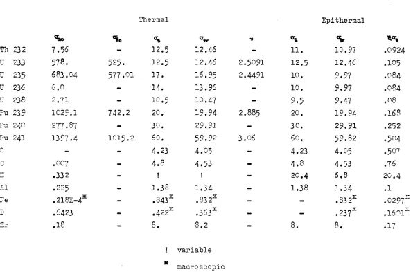
II.1. EXPO experiments
A number of exponential measurements have been made at Euratom to find the buckling of a lattice composed of "7rod cluster" elements fuelled with uranium carbide and cooled with diphyl.
The measurements were made for ten different pitches ranging from 2230 cm. More details are given in ref.l6. The inaccuracies are mainly originated by the limited number of test elements contained in the experimental facility giving rise to large inhomogeneity effects etc.
_2
The error however is supposed not to exceed ,2m . A plot of the cal culated curve, together with some measured data is given in fig.l. The agreement is very satisfactory for lattices with a pitch è 22 cm. The differences are notably smaller than the inaccuracies remained at the interpretation of experimental results.
- ¿Ö
-II.2. CISE Experiments
A set of buckling measurements in Aquilon II has been performed by CISE in contract vrith Euratom (ref.17). In this experiment the successive replacement method has been used. The tested configu rations were madeup of concentric annuii elements, fuelled by natural uranium and having polystyrene to simulate the hydrogeneous coolant.
Two concentrieal tubes have been used in the measurements; AC. a composition of two concentrieal tubes filled with "coolant" and AC«, a tube with a bar of the same outer most size as the internal tube of AC. . Two densities of polystyrene have been used with respective densities of .307 and .578 gram/cm indicated by resp. T, and T^ in the fuel element index.
One sees in fig. 2 that the best agreement is found for the tubeandbar element AC_ at high pitches, where the difference is within the
accuracy.of the measurements. For the A C cluster the disagreement between experiment and theory is the greatest of all the comparisons
2 made and is of the order of .5 m
The only encouragement is here, that the Euratom scheme gives even better results than those obtained with the fundamental scheme used at CISE. In both cases the calculations give to low results (Ref.l8).
Besides the fundamental scheme a correlated one has been constructed by CISE with adjustment prameters, in the resonance integral and k^ . In
table 6 and 7 these results are compared with ours.
The factor ρ in the CISE results given in the tables is corrected such, to give the correlated k,,, with the normal foui* factor formula. Al though differences in the partial parameters occur, one sees that their total effect on the infinite multiplication factor is very small,
2
The main differences arise in the values of the migration areas 1 and τ ,
29
-II.3. Savannah River experiments
A generalised study of the reactor physics of natural uranium, heavy water systems has been made at Savannah River Laboratories (Ref.19). Detailed nuclear parameters *\,&,p ,f etc. were measured in the PDP for Do0 moderated lattices of natural uranium rod clusters of 1,
3,7 and 19 rods. These rods were 1 inch in diameter and cladded with
.032 inch of aluminium.
Apart from this way of obtaining the buckling this parameter was ob tained by flux mapping analysis.
The first method however, can only be performed with the aid of a theoretical scheme, which is only a raw pitture of reality. However it helps us to estimate the accuracy of every parameter .
It seems therefore, that the most confidence could be given to the
flux mapping experiments. The figures of all the experiments are given in
Pig.3-5.
For any of the 4 cluster types, measurements have been made for a wide range of pitches.
Tables 8-10 give the comparisons of the detailed nuclear parameters obtained from the experiments with the calculated ones.
One sees, that the Savannah River TJ and Β are always greater than the ones calculated by us.
Their ρ values are mostly greater for small pitches and may sometimes obtain smaller values at large pitches especially in the small clusters.
Their f values are always a little smaller than the ones calculated by us.
Nevertheless the Savannah River k-inf values are always greater by some percents, the difference increasing at larger pitches.
This difference however is compensated by the fact that their values of the migration parameters are greater.
All these differences result in PLUTHARCO calculated bucklings, which
are too large for the 3ingle rod compared with both types of experiments.
30
-For the lowest pitches calculations of the spatial constants wert· nade by using the CANDU-scheme as well as the TERMIDOR scheme.
The plots show, that for large clusters the TERMIDOR results are in favour to the CANDU ones.
_2
Differences in the 7-rod cluster case amount to about .4 m at under-moderated lattices. For single rod lattices the difference is of the same order of magnitude but of opposite sign.
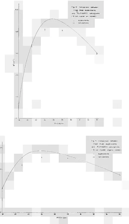
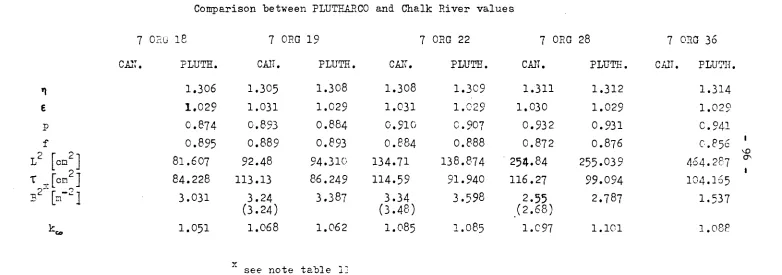
II.4. Chalk River experiments
In the ZED-II reactor at Chalk River, a zero energy critical facility, a series of experiments ha3 been made of the spectral constants, Westcott values in the fuel and moderator regione, thermal neutron spectrum
spatial distributions relative conversion ratio's and fast fission ratio's. With the aid of these figures the detailed nuclear para meters could be calculated.
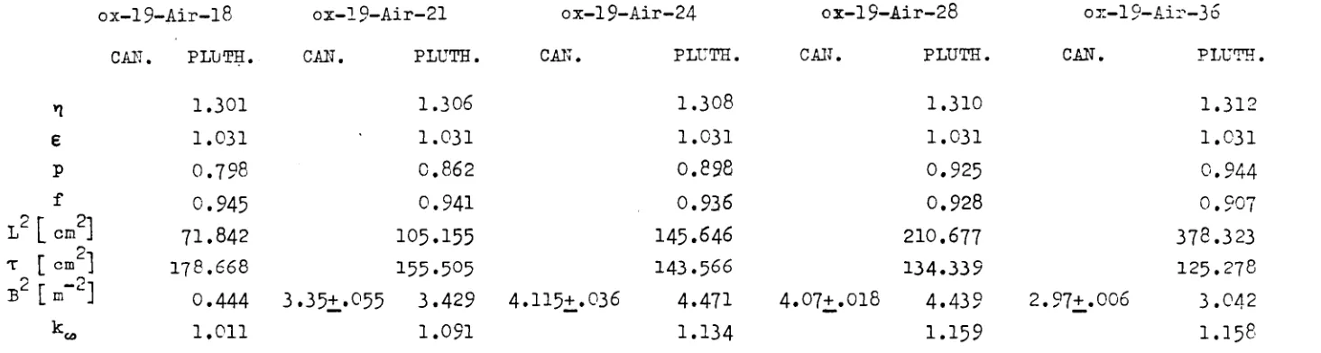
To obtain a broad experimental background for recipes to be checked measurements were made for various lattice arrangements, i.e. with as variables the lattice pitch, coolant (organic - HB._, heavy water and air)j fuel compounds (uranium metal and oxide) and cluster type (7 and 19 rod hexagonal with about the same fuel volume per cm).
From above mentioned parameters the critical buckling was calculated.
Apart from this results direct buckling measurements were made (Ref,20-23). Comparisons with PLUTHARCO calculations have been performed for oxide
fuel only.
The clusters are identified by a symbol which is devided into three parts (eq.7 D_0 18 ) the number of fuel pins per cluster, the coolant type and lattice pitch respectively.
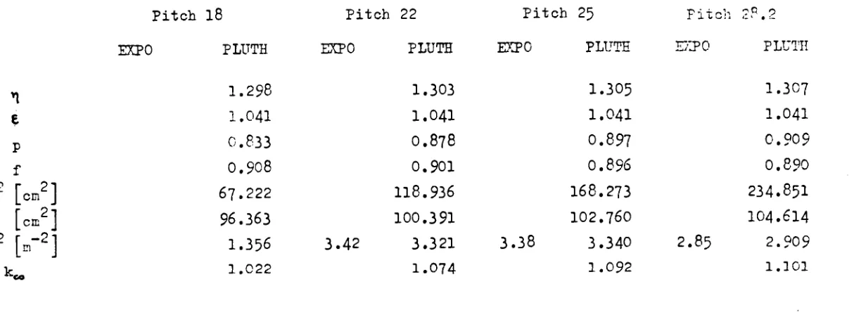
For the 7 rod clusters the comparisons with detailed data are given in Table 11-13, the bucklings in f ig, 6-8} for the 19 rod olusters resp. Table 14-16 and fig.9-11.
A very good agreement is found for rj t e and f , with differences
31
-2
The migration areas L and Τ show relatively the greatest
o
differences with the CANDU results L~ being too great and ~ too smal] by abotit 8 ;' . For the 7 rod clusters the differencer:
2
of L and Τ are of different sign, in the 19 rod case both are appreciably smaller than the ones obtained from the measure ments. As a result of this, one sees (Fig. 6-8) that the calculated
Ducklings are better in agreement with the experiments (differences about .1 m~ ) for the 7 rod cluster than for the 19 rod cluster,
-2
which are all too high by at most .5 m · The measured Westcott r factor for the Chalk River cluster has been compared with PLUTHARCO. The measured values turned out to be 3 /oo smaller independent of the pitch.
The measured moderator spectral constants correspond very well with the calculated ones too, the last ones being smaller by about 3-5 K.
The calculated fuel spectral constants however, are too low by 30 Κ for small pitches decreasing to 15 Κ for large pitches. The resulting
_2 buckling difference on the other hand never exceed ,2m ,
11,5. Conclusions
As conclusion may be said that in general the detailed nuclear para meters n, ε , ρ and f were good compared with the measurements,
2
The migration area L and Τ show relatively much greater differences 2
than the former four. Whether L shows differences in both directions little can be said from the comparisons. However the Fermi-age calculated in PLUTHARCO is without exception smaller than the values quoted from experiments.
The buckling values are generally sufficiently near to the values given by the experiments. Differences are mostly within.3 m~ .
Furthermore the results show that for small pitches systematicly too low values of the buckling are obtained with PLUTHARCO. This may be caused by two effects:
1. Inaccuracy in the scheme describing the flux disadvantage factors in the epithermal range,
32
Fig.1 Comparison between
EXPO experiments
and PLUTHARCO calculations
o experiments
- * - calculations
28
30
— 4 —32
34
36
60
Fig.2 Comparison between CISE experiments and PLUTHARCO calculations
o experiments >— — calculations
AC-2-T1 5.0
E "ω
4,0
AC-1-T3
3 0
20 22 24
PITCH (cm)
7.0
60
5 0
E
'ω
4.0
3.0
2.0
Fig. 3 Comparison between Savannah River experiments
and PLUTHARCO calculations (Single rod )
— PLUTHARCO
0 foil experiments ■ flux mapping
TERMIDOR
β.0
7.0
Fig.4 Comparison between Savannah River experiments and PLUTHARCO calculations
( 3 rod cluster) — PLUTHARCO
• foil experiments . flux mapping « TERMIDOR
6.0
E
5.0
4.0
3.0
10
PITCH ( i n . )
Fig. 5 Comparison between Savannah River experiments and PLUTHARCO calculations
( 7 rod cluster ) — PLUTHARCO
• foil experiments " flux mapping
Flg. 6 Comparison between
Chalk River experiments and PLUTHARCO calculations
( 7 rod cluster, D;0 cooled )
° experiments
— calculations
26 26
PITCH (cm)
6.0
5.0
~
'ε
"m
4.0
3fl
i /
ζ' } ^ ^ ^ " ^
Fig. 7 Comparison between Chalk River experiments and PLUTHARCO calculations
( 7 rod cluster , air cooled ) — ^ ^ · experiments
^ ^ v ^ — calculations I ^ s .
te 22 24 26 28
PITCH (cm)
Fig. 8 Comparison between Chalk River experiments and PLUTHARCO calculations
( 7 rod cluster. organic cooled) • experiments -m- calculations
26 28 PITCH (cm)
5.0 Fig. 9 Comparison between
Chalk River experiments and PLUTHARCO calculations (19 rod cluster, D;0 cooled )
Flg. 10 Comparison between Chalk River experiments and PLUTHARCO calculations ( 19 rod cluster. air cooled )
[image:42.595.75.516.28.793.2], experiments -~- calculations
Fig 11 Comparison between Chalk River experiments and PLUTHARCO calculations ΐ 19 rod cluster .organic cooled)
» experiments
-*~ calculations
26 28
39
-III. Compilation of formulae
A complete set of formulae is given in the next part of the report together with a list of symbols.
List of symbols
III.l. Cross sections a. Subscripts
The first index refers to the type of reaction, the second to the type of material.
Type of reaction
a = absorption - capture + fission c = capture
e = fast elastic scattering f = fission
i = fast inelastic scattering s = elastic scattering
t = total = absorption + scattering tr = transport
Type of material c = fuel
g = canning m - moderator
0 » coolant (organic or heavy water) r = filler
t = assembly of pressure tube (l) and calandria tube (3 ) u = uranium
b. Superscripts e = epithermal
PE - fertile isotope (Th-232, U-238, Pu-240)
FI = fissile isotope (U-233, U-235, Pu-239, Pu-2*l) t = thermal
*æ
.III. 2. Physical parameters a.
EXSAP = extra absorption in SAP due to impurities (value at 2200/secxlO ) F (i) = atomic fraction of isotope i
f(l/v)= spectrum mean microscopic l/v abs.cross section/barn (2200m/sec) g = Westcott averaging factor
HBR = percentage of high boiling residues in santowax M » = molecular number
N = number of nuclei / cm
N, = number of Hatoms/organic molecule n
N = number of Catoms/organic molecule Pu = purity of heavy water
r = epithermal flux fraction s = Westcott factor
S = reference density Τ = temperature ( C)
Τ = spectral constant ( K ) Τ = room temperature (293 K)
ALFA = weight percentage of A1„0 in SAP 3
Ρ.ΠΟ = density (gr/cm )
RLTFÎ = inverse reference transport cross section BSH = averaged scattering cross section/Hatom
SAL = effective absorption section (averaged over a Maxwellian flux at fuel temperature Τ ) due to alloys contained in the fuel
CHlí = additional heavy water absorption section due to impurities other than light water (value at 2200m/sec)
b. Subscripts
c Fuel s = Santowax
d = M phenyl SAP · Sintered Aluminium Power
g = canning t ■ assembly of pressure tube gr = graphite (l) and calandria tube (3) m = moderator
0 » coolant (organic or heavy water) Oi = inner coolant
- 4-Ί
-I -I -I . 3 . Geometrical parametern a.
V = volume
Ζ = square pitch
b = lattice cell radius a = bundle radius
S = bundle effective fuel surface / cm
R = inscribed circle between fuel rods in cluster c
Y =» escape probability
b, subscripts
For region identification see 2. (physical parameters) u = total (in connection with S)
f = outer (in connection with S) t, = first tube (pressure tube) t_ ■ second tube (isolation tube) t, = third tube (calandria tube) t = three former tubes
B = bundle c. superscripts t = thermal f = fast
k2
-FUEL
1. Calculation of spectral constants
a.
Correlated spectral constants
♦ 0.6o*4. Vc . 2¿. . ( V T , . ) ♦ 0.00161, . (V«, ♦ Vt l) Σ ^ . ( T . . T J
+ ( V1^ ) ( 4 " ° * · - 0.2 β ) ♦ T„ + »oor
(T-)r - (T*')oo « C < ) f*( T : )~
2
(
T-)ia » (
T0 r
røi>
« ( M r
C7«)«, · T« +3 o o r
b.
Spectral constants
directly entered
c.
CM.
(T*)h
TERMIDOR spectral constants for calculating l.cross sections
4
(
T0,
V. »/oo 2
(Mr
(T„)r
4
»'CO-For non-i-cross sections
data are entered directly
Ό
-2. Calculation Westcott constants
S_(2»C} . so ■ ƒ j * i
T».
% (2*°) · *-(«»»>
/ i + 4 VC- N. 41SOOO ■ f ( g 4 o )
S « f
ƒ 1 4 4 . ^ . H . F ( i M ) . &<oo
5 , ( 2 ^ . * ^
/ < * 4 - ^ . W .
y s.
F ( a & q ) . a i o o
3. Calculation Westcott cross sections
*α(Ό - <k*(').[<j(') + T . S ( l ) J
¡ . a
TK
t%%
a U 2»«
% ( ' ) - %*(»)·[ «,0) ♦ « ■ * ( ' ) ]
»
U »»»
L J 4 U 3ftS
s
υ « ι
6 Pu 2V)
- H<+
-Α. Mixed fuel microscopic cross sections
<
(*f
rt , ■
Í
(HS)*
Ί · 1
S
2
la* Χ1
SΣ
¡«Λ (2
i»1 % Σ Ί·ι2
Ι . Λi
ρ(θ·Αθ)
PO)· «»('O
y
V_ 2<?V64 Tw
F(¡). *
f(¡). / f S
s
wg-O)
( v Cf)W
<r
w ι , «^ 0
ν m m ■ « e2
i-1 8 » i.-t χ2
ϊ · 1
2
t . 1
e
5
¡«1
.w
«;
w
F ( i ) . . ( i ) . T
f( i ) . / T J M
" 4 'n
KO· [<(!)♦ ico]
F ( ¡ ) .
σ * ( θ
F
Ü) · < 0 .
KO · (*«.)\0
F ( i ) . e - W ( i )
F ( O . * * > ( . )
Ό ) . Ο*Γ(0
KO · «i
wC
!)
- ; . ρ(ί)· ς** co
- 2,
Ό)· «JO)
- 2 PO)·
•¡
ί
,\·.)
l a i
I ■ 1 1 Th
t υ
»
u
4 υ
s
υ
* Pu
7 ft*
S ΤΙι
M l
ass
1 » 6
a«c a»»
a«9 24o
^5
-5. Fertile isotope macroscopic cross sections
Ί.™ - 2 F(U). Ν . fr(W. - / τ "»·& - Σ Σ™*(1»)
17». £ roo... ,%> . à i r - w
U.4 L J t . ,
k > 1 T h 2 M 2 U i U 5 Pu 240
6. Resonance integrals
M
kõ>
iv(u.j)
U l ( l c ) ,
U2 ( I t ) .
Fu»ic+ion o í I T
fUMCHovi o F [ Τ
F ( U ) . Ν. A ( W . i )
F ( U > . N . B ( U . j )
s / r - K w )
k · ι Th i»a β υ α·»»
» fu 240
j 1 Nefel 2 Ox.de 5 Monocarb. 4 ü i c e r b i d e
7. Fissile
isotope macroscopic cross sections
. F i t r
.
-
^ ( 0 · Ν. τ (I) . / I . i l L i
.Λ * V 4 τ
L . H
S 4
<+6
8. Fuel compound macroscopic cross sections
K
· »·[**♦ CO) ]♦*
Σ\
. *.[<♦ ^ ( ο ]
ζ.
-
Ν· [ < « C o > ]
zi
-ζ : ■
»s ■
(e M'
-Ν .
Ν .
Ν .
Ν
[<-[<'
[<-[
«V
C ω]
Ceo]
Co)]
f ♦(**>·<«)
]
(,Z,f>. H. (.,)«
2?'
• H. [ e * . C O ) ]
Σ.
1" · »■[«?♦«■>,]
ι." · «•[«["♦«¡SO)]
Z ,W
.
Η.
^ '
ï
c<" . ».[ ««.«Wpj.tir.etf»]
«f ■ »■[ "Λ'¿"o]
■'+7
-ORGANIC COOLANT (C^H
N
)
d.
Thermal cross sections
4
- ^
[
Ν.
[rvj; ^ -
4 5s
] · f«
A.
Resonance and epithermal cross sections
Σ*. - 0,6034 rN|) flo.4 .(-UO.CaV?) ·+ Nc .4.6* . (<-ο.ο5β) 1 . ^»β
feZ»)' - o C^ *4 [ N „ 2O.4 + r ^ . ο . < β β « . 4.6«.] . P0
Fast cross sections
2W „ ο.6o24 Γ Ν . 4,
t
j W e ο.6ο24
β
£ 2 * [ t 1H 4*»4 -r Nc. 4 * , f #
|^NM . 0.4S + Mc. 4 * 7 1 . Oe
•¿.CO . O . U * ΓΝ^ λΑ6, 4 Nfc . o.nj . pe
'+8
-SANTOWAX ( C
1 8H
1 4)
Thermal cross sections
K
Ί . 0 9 9 - o 0 0 0 - f a Τ ■*· o . o o o q . χ
o.6eg» Γ ΛΑ. ο . · Μ + 18 ο . ο ο 4 β ο ]
X4. ^MC T ) ♦ 4*. 4.1 ]
2 v>
0 . & 0 2 4
2fto
o.fco24 f 44 αio
( x . X Ufc'ù ·, T in »C )
/4Τ„
?*r·
f·
* ;
Resonance and epithermal cross sections
(*
2
*Γ
' ° * * Γ 14 2ο.Λ + 1 * 4 . - 6 . pt
6 o* 4 Γ >J4 . 2o.4 ( 4 - 0 . 6 4 V 7 ) + 1» . 4 . 6 t ( l - 0 . o S « ) ¡. fs
Γ 4 4 . 2o.4 + 4 » . o i s 8 g . 4 66, . pfc
o.feoa.4 •3·»
Fast cross sections
:(M O.feo24
2
e W
2 i o
o 6 o l 4 <So
0 . 6 0 2
4&0 o.<oo24
Ä o ο.6ο24
I t o
4 4 . 4 .gì + I * 4
0.4S + 1 8 . 4.2-?
I L Γ 4 4 . 4.4C 4 4 8 o.zi
4 4 4 SC ■» 4 8 . « T *
Γ ^ 4 . 4 SC + 4 8 . i.ft
p.