Design of PIDA Controller Using Bat Algorithm for
AVR Power System
D. K. Sambariya
∗,
D. Paliwal
Department of Electrical Engineering, Rajasthan Technical University, Kota, 324010, India
Copyright c⃝2016 by authors, all rights reserved. Authors agree that this article remains permanently
open access under the terms of the Creative Commons Attribution License 4.0 International License
Abstract
In this article, a new proportional, integral, derivative, and acceleration (PIDA) controller for an au-tomatic voltage regulator power system is presented. The controller parameters are designed by considering as an optimization with minimization of square error using bat algorithm. The response of the bat algorithm optimized PIDA (BA-PIDA) controller are observed and compared to the controllers in the literature. The superiority is validated in terms of performance indices (ITAE, IAE and ISE.Keywords
Proportional Integral Derivative Acceleration (PIDA), Bat Algorithm, Current Search Algorithm, Genetic Algorithm, Tabu Search1
Introduction
The application of control system in the design of an effi-cient and economic controller is always a challenge to con-trol engineers. The different concon-troller structures and design methodologies are always the concerns of researchers. The proportional- integral-derivative (PID) controllers are gener-ally preferred controllers in industrial applications [1]. In many cases, the systems are modeled as a third order. In fact, the traditional motion control system such as an Ac mo-tor with position control is properly modeled as a third order plant without crude approximations [2]. The design of PID controllers is not always easy in some cases. It is the reason that a new structure of controller becomes necessity of such systems [3].
In 1996, Jung and Dorf proposed a new structure of con-troller and termed as proportional- integral-derivative and ac-celeration (PIDA) controller [2]. It consists of three numbers of zeros and poles but two poles may be neglected in the de-sign process. It is addition of a zero in the standard PID struc-ture to derive the PIDA strucstruc-ture of the controller.The intro-duction of an extra zero to the PID controller is to change the root locus of the third order plant in order to make dom-inant roots more domdom-inant by eliminating the effects of non-dominant roots [4].
Initially, the design of PIDA controller parameters have been determined using analytical method. In this method two characteristic equations; one formed with desired root loca-tions with specificaloca-tions based on the design criterion, and another one with the nominal control structure were equated to deduce the parameters of PIDA. It have been considered to design PIDA controller for third order systems and extended for the control of an AC motor system [2]. The application of PIDA were considered for a servo motor driving a load through a long shaft or transmission system in [5]. Sambariya and Paliwal, 2016 have presented the optimal tuning of PIDA controller parameters using harmony search algorithm in [6].
Dal-Young et. al, 2001, highlighted the higher overshot during the rise time while designed PIDA controller with an-alytical method. It were mitigated using pre-compensator to PIDA in ac motor control in [7]. The performance of PIDA controller for the third order system have been improved us-ing Kitt’s method and extended to discrete system [8, 9]. The design of PIDA for third order systems were presented using an algebraic design approach which also utilized the genetic algorithm (GA) to achieve design optimality in [10].
The recent current search algorithm have been proposed to determine the PIDA parameters for automatic voltage regu-lator (AVR) system in [4]. It have compared the system re-sponse with PIDA controller using genetic algorithm (GA) and tabu search (TS) algorithm and proved to be superior with current search algorithm. In this paper, the PIDA con-troller parameters are designed using bat algorithm.
2
Problem formulation
2.1
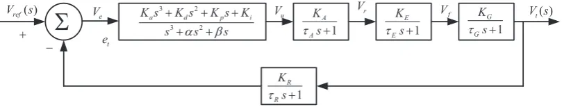
AVR SystemThe application of an automatic voltage regulator (AVR) in the generator excitation system to control the reactive power flow and regulate the generator voltage was presented in [11, 12]. It holds the terminal voltage of a generator at a specified level. It critically affect the security of the power system [3]. The AVR consists of amplifier, exciter, generator, and sen-sor. A simplified AVR system controlled by the PIDA con-troller is represented by the block diagram in Fig. 1, where
Ve is the error voltage between the reference input voltage
Vref(s)and sensor voltage, whileVu,Vr, andVfare the
con-trolled, amplified, and excited voltage signals, andVt(s)is
the output voltage. The detail on the linearized AVR system is mentioned as following [4]:
2.1.1 Amplifier model
The amplifier model in AVR system is expressed in Eqn. 1. The gain and time constants are presented by KA and
τA, respectively. The recommended values of KA andτA
are in the range of 10 to 400 and from 0.02 to 0.1 seconds, respectively [13]. The considered values of these parameters is asKA= 10 andτA= 0.1 seconds.
Vr(s)
Vu(s)
= KA
τAs+ 1
(1)
2.1.2 Exciter model
The exciter model transfer function is presented in Eqn. 2. The range of gainKE and a time constantτeis 1 to 400
and 0.25 to 1.0 seconds, respectively [13, 11]. The selected values of these parameters areKE= 1 andτe= 0.4 seconds.
Vf(s)
Vr(s)
= KE
τEs+ 1
(2)
2.1.3 Generator model
The transfer function representation of generator model in AVR system is given in Eqn. 3. It consists with a gainKG
and the time constantτG. The range may vary between 0.7 to
1.0, and 1.0 to 2.0 seconds, respectively [13]. The considered values are 1 and 1 second, respectively.
Vt(s)
Vf(s)
= KG
τGs+ 1
(3)
2.1.4 Sensor model
The sensor model is considered as a simple first-order transfer function as stated in Eqn.4. The gainKR, and the
time constantτG in the range from of 1 to 10 and 0.001 to
0.06 second, respectively [13]. In this work,KR= 1 andτG
= 0.01 second are considered.
Vs(s)
Vt(s)
= KR
τRs+ 1
(4)
2.2
PIDA ControllerThe transfer function representation of the PIDA controller is expressed in Eqn. 5. The termsKp,Ki,Kd, andKain this
controller are the proportional, integral, derivative, and accel-erated gains, respectively, whiled, andeare filter parameters. The transfer function in Eqn. 5, is alternative presented in a polynomial form in Eqn. 6 with the parametersKp,Ki,Kd,
Ka,α, andβ, respectively [4].
Gc(s) =Kp+
Ki
s + Kds
s+d+
Kas2
(s+d) (s+e) (5)
Gc(s) =
Kas3+Kds2+Kps+Ki
s3+αs2+βs (6)
2.3
Objective functionIn this article, the design of PIDA controller is carried out considering the problem as optimization. The objective func-tion during optimizafunc-tion is considered as in Eqn. 7 with pa-rameter bounds as in Eqn. 8. The optimization is considered with minimization of error signal as in Eqn. 7.
Minimize:
J = T∫sim
t=0
|Vref(t)−Vt(t)|
2
dt (7)
Subjected:
Kmin
a ≤Ka ≤Kamax
Kmin
d ≤Kd≤Kdmax
Kmin
p ≤Kp≤Kpmax
Kimin≤Ki≤Kimax
αmin≤α≤αmax
βmin≤β≤βmax
(8)
3
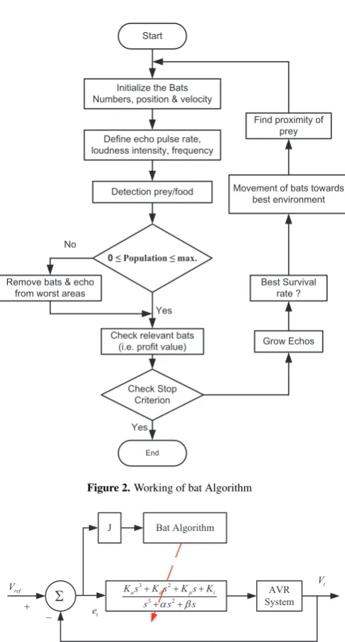
Proposed Bat Algorithms
The bat algorithm is based on the echolocation behaviour of Micro bats [14]. In echolocation, each pulse generated by a micro bat may last only for 8 to 10 milliseconds with a frequency ranging from 25 kHz to 150 kHz, which corre-sponds to the wavelengths of 2 mm to 14 mm [15]. In BA, the echolocation characteristics of Micro bats can be ideal-ized with the following assumptions.
• It is assumed that the bats are able to detect distance of prey, background obstacles and difference in the avail-able prey/food in the search path in some magical way using echolocation property [16].
• Ankth Bat may randomly fly with location asxk,
ve-locity asvk, frequency asfminbut with varying
wave-length as λk and loudness of echo as A0 to search
food/prey. The Micro bats have an ability to adjust fre-quency (wavelength) of the emitted pulses of echo and rate of pulse emission out ofr∈[0,1]according to the distance of their prey/food [17].
• The loudness of the echo pulse should be varied as re-ducing with decreased distance of the food, i.e. from largeA0to a minimum valueAmin(at target/prey
3 2
3 2
a d p i
K s K s K s K
s as bs
+ + +
+ +
+
-S
te
e
V
1 A
A
K s
t + 1
E
E
K s
t + 1
G
G
K s
t +
1 R
R
K s
t + u
V Vr Vf
( ) ref
[image:3.595.103.508.96.173.2]V s V st( )
Figure 1.Representation of closed loop AVR system with PIDA controller
3.1
Procedural StepsLet in an optimization problem; the objective function be represented by Minimization ofF(x)which is subjected to
xk∈Xk,k= 1,2,3, ..., N[19].
3.1.1 Initialization
• As an initial step, the bat population is initiated as posi-tion and velocity asvkwithk= 1,2,3, ...., n.
• Initial pulse frequency is defined asfk∈[fmin, fmax]. • The pulse ratesrk and the loudnessAk are also set as
above
• Check number of iterations ort < Tmax
3.1.2 Generation of new solutions
• New solutions may be generated by adjusting the pulse frequency and keeping wavelength as constant.
• For each bat (k), its position xk and velocity vk in a
d-dimensional search space should be defined. xk and
vkshould be subsequently updated during the iterations
[20, 21]. The new solutionsxtkand velocitiesvtkat time steptcan be calculated by:
fk=fmin+ (fmax−fmin)β (9)
vkt =vkt−1+ (xkt−1−x′)fk (10)
xtk =xtk−1+vtk (11) where,β is defined for uniform distribution as a vector and selected asβ ∈ [0,1]. Thex′stands as the best location in search space after comparing solutions of all thenbats [22]. The product offkandλk represents the velocity increment.
The velocity increment can be adjusted by changing one and keeping fixed another according to a problem. The generally used range of frequency is0 ≤ f ≤ 100and each bat at initialization step is selected fromf = [fmin, fmax][23, 24].
3.1.3 Local Search
Once the best current solution is selected among the avail-able solutions, then a new solution is generated by using lo-cal random walk and assigned to each bat as in Eqn. 12. If ε ∈ [−1, 1] represents a random number range and
At = < Atk >stands for average value of loudness of all initiatednbats at timet.
xnew=xold+εAt (12)
3.1.4 Bat flying and Generation of a new solutions
As the number of iteration increases, the loudnessAk and
the raterk of pulse emission have to be updated. As a
mi-crobat reaches to its target/prey the rate of pulse emission increases while the loudness decreases. The loudness is gen-erally selected from[A0, Amin] = [1,0]. TheA0= 1
repre-sents the maximum loudness of emitted pulse by microbat in search of prey, whileAmin = 0indicates that the microbat
got the target/prey and not emitting any loudness. Thus, the loudness and the rate of pulse emission is updated as.
Atk+1=αAtk (13)
rkt+1=r0k[1−e−γt] (14) where, α andγ represent the constant values. Here, αis similar to the cooling factor of a cooling schedule in the sim-ulated annealing [25] and the range of these constants is as
0< α <1and0< γ.
Atk →0 (15)
rtk→rk0 (16) To make optimization simpler, the value ofαandγshould be selected as same, therefore, in this studyα = γ = 0.9. As in Eqns. 15 - 16, the initial loudness and emission rate may be represented byA0
kandr0k, respectively. The value of
emission rate at timetcan be selected fromr0
k ∈[0, 1].
3.1.5 Checking the stopping criterion
If the maximum count of iterations is reached as a stopping criterion is satisfied, then the process of computation is ter-minated. Otherwise, go to steps 3 and 4 to repeat the process.
4
Results and discussion
The PIDA controller for AVR system is designed using bat algorithm (BA). The performance of BA and the BA-PIDA controller is designed in the next sections.
4.1
Performance of bat algorithmThe scheme of optimization of PIDA controller using BA with an ISE based objective function is considered and shown in Fig. 3. The initializing parameters for bat algorithm are as mentioned following and the lower and upper bounds for PIDA parameters are considered as in Eqn. 17.
Initialize the Bats Numbers, position & velocity
Start
Detection prey/food
0≤ Population ≤ max.
Check relevant bats (i.e. profit value) Remove bats & echo
from worst areas
Check Stop Criterion No
Yes
Yes
End
Grow Echos Best Survival
rate ? Movement of bats towards
best environment Find proximity of
prey Define echo pulse rate,
[image:4.595.44.287.78.529.2]loudness intensity, frequency
Figure 2.Working of bat Algorithm
3 2
3 2
a d p i
K s K s K s K s as bs
+ + +
+ +
AVR System +
ref
V Vt
-S
t e
[image:4.595.37.537.88.528.2]J Bat Algorithm
Figure 3. Representation of optimization scheme of the PIDA controller
using bat algorithm
• Number of generations selected as 100
• Loudness (constant or decreasing) selected as 0.5 • Pulse rate (constant or decreasing) selected as 0.5 • Frequency minimum selected as 0.01
• Frequency maximum selected as 2 • Number of dimensions selected as 6
50≤Ka≤150 450≤Kd≤550 750≤Kp≤850 350≤Ki≤450 550≤α≤650 900≤β ≤1000
(17)
[image:4.595.297.545.113.183.2]The performance of bat algorithm in terms of fitness func-tion and iterafunc-tions is shown in Fig. 4. The unknown pa-rameters of the PIDA controller are recorded at the end of
Table 2.Comparison of system response in terms of Performance indices
Controller ITAE IAE ISE
PIDA-BA (Proposed) 199.79 19.724 19.585
PIDA-CS [4] 199.97 19.765 19.697
PIDA-GA [4] 199.90 19.743 19.650
PIDA-TS [4] 199.89 19.760 19.680
iteration 100, where, the process of optimization get termi-nated. These parameters are recorded in Table 1. It also en-list the parameters with genetic algorithm (GA), tabu search (TS) and current search (CS) as reported in [4].
0 20 40 60 80 100
1992.2 1992.4 1992.6 1992.8 1993 1993.2 1993.4 1993.6 1993.8
Iterations
Fmin
Fitness Function
Figure 4.Representation of fitness function using bat algorithm
4.2
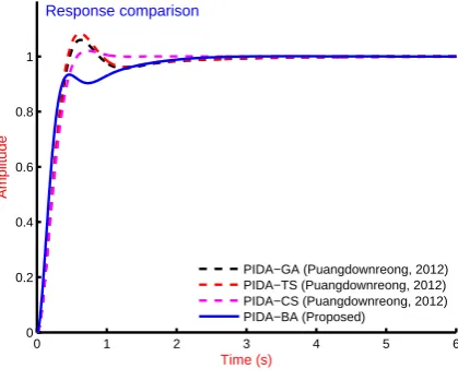
Simulation resultsThe simulation study of the AVR power system is caried out without controller and with PIDA controllers. Initially, the system without controller is simulated and the response is shown in Fig. 5. The AVR system is equipped with PIDA controller with parameters in Table 1. The responses are ob-served and compared as shown in Fig. 6. It is clear from the figure that the response with proposed BA-PIDA outperforms as presented in [4]. The critical analysis was carried out in terms of performance indices. These performance indices are integral time weighted error (ITAE), integral absolute error (IAE) and integral of squared error (ISE) as defined by Eqn. 18 - Eqn. 20, respectively. The detail on performance in-dices may be referred as in [26, 27, 28, 1, 29]. The observed performance indices are enlisted in Table 2. The ITAE value with proposed PIDA-BA controller is 199.82 which is lesser as compared to 199.97. 199.90 and 199.89 with controllers in [4]. It means that the proposed PIDA-BA outperforms the PIDA-CS, PIDA-GA and PIDA-TS.
IT AE= Tsim∫
0
t |yo(t)−yr(t)|dt (18)
IAE= Tsim∫
0
[image:4.595.302.523.275.449.2]Table 1.Comparison of the PIDA parameters
Controller Ka Kd Kp Ki α β
PIDA-BA (Proposed) 149.9821 549.5267 755.1120 350.0000 550.2274 1000.000
PIDA-CS [4] 101.0102 498.9516 799.1201 394.0112 589.5411 965.0501
PIDA-GA [4] 99.1016 577.5625 784.0012 342.1474 592.9654 912.4471
PIDA-TS [4] 102.2365 592.3258 824.8747 341.6321 596.1974 854.1247
ISE= T∫sim
0
|yo(t)−yr(t)|
2
dt (20)
0 5 10 15 20
0 0.2 0.4 0.6 0.8 1 1.2 1.4 1.6
Time (s)
Amplitude
System without controller
Figure 5.Step response of the AVR system without controller
0 1 2 3 4 5 6
0 0.2 0.4 0.6 0.8 1
Time (s)
Amplitude
Response comparison
[image:5.595.72.282.502.676.2]PIDA−GA (Puangdownreong, 2012) PIDA−TS (Puangdownreong, 2012) PIDA−CS (Puangdownreong, 2012) PIDA−BA (Proposed)
Figure 6.Step response of the AVR system with controllers
5
Conclusion
The optimum PIDA controller is obtained using bat algo-rithm. The performance of this controller is compared to that of with current search, genetic algorithm and tabu search algorithms and outperforms these. The effectiveness of the proposed BA-PIDA is presented graphically and in terms of performance indices (ITAE, IAE and ISE).
REFERENCES
[1] D. K. Sambariya and R. Prasad, “Design of robust PID power system stabilizer for multimachine power system using HS algorithm,” Ameri-can Journal of Electrical and Electronic Engineering, vol. 3, no. 3, pp. 75–82, 2015. [Online]. Available: http://dx.doi.org/10.12691/ajeee-3-3-3
[2] S. Jung and R. Dorf, “Analytic pida controller design technique for a third order system,” inDecision and Control, 1996., Proceedings of the 35th IEEE Conference on, vol. 3, Dec 1996, pp. 2513–2518 vol.3. [Online]. Available: http://dx.doi.org/10.1109/CDC.1996.573472
[3] D. K. Sambariya and V. Nath, “Optimal control of auto-matic generation with autoauto-matic voltage regulator using particle swarm optimization,” Universal Journal of Control and Automa-tion, vol. 3, no. 4, pp. 63–71, 2015. [Online]. Available: http://dx.doi.org/10.13189/ujca.2015.030401
[4] D. Puangdownreong, “Application of current search to opti-mum pida controller design,” Intelligent Control and Automa-tion, vol. 3, no. 0, pp. 303–312, 2012. [Online]. Available: http://dx.doi.org/10.4236/ica.2012.34035
[5] C. U-thaiwasin, S. Sujitjorn, Y. Prempraneerach, and J. Ngamwiwit, “Torsional resonance suppression via pida controller,” inTENCON 2000. Proceedings, vol. 3, Sept 2000, pp. 498–503 vol.2. [Online]. Available: http://dx.doi.org/10.1109/TENCON.2000.892316
[6] D. K. Sambariya and D. Paliwal, “Optimal design of pida controller using harmony search algorithm for avr power system,” in6th IEEE International Conference on Power Systems, (ICPS-2016), 2016, pp. 1–6.
[7] H. Dal-Young, L. Ihn-Yong, C. Young-Seung, L. Young-Do, and C. Boo-Kwi, “The design of pida controller with pre-compensator [for induction motors],” in Industrial Electronics, 2001. Proceedings. ISIE 2001. IEEE International Symposium on, vol. 2, 2001, pp. 798–804 vol.2. [Online]. Available: http://dx.doi.org/10.1109/ISIE.2001.931570
[8] P. Ukakimaparn, P. Pannil, P. Boonchuay, and T. Trisuwannawat, “PIDA controller designed by kitti’s method,” inICCAS-SICE, 2009, Aug 2009, pp. 1547–1550.
[9] K. Smerpitak, P. Ukakimaparn, T. Trisuwannawat, and P. La-orsri, “Discrete-time PIDA controller designed by kitti’s method with bilin-ear transform,” inControl, Automation and Systems (ICCAS), 2012 12th International Conference on, 2012, pp. 1585–1590.
[10] S. Sornmuang and S. Sujitjorn, “Ga-based optimal PIDA controller design,” inProceedings of the 10th WSEAS international conference on Systems theory and scientific computation. World Scientific and Engineering Academy and Society (WSEAS), 2010, pp. 192–197.
[11] V. Nath and D. K. Sambariya, “Analysis of AGC and AVR for single area and double area power system using fuzzy logic control,” Inter-national Journal of Advanced Research in Electrical, Electronics and Instrumentation Engineering, vol. 4, no. 7, pp. 6501–6511, 2015. [12] D. K. Sambariya and V. Nath, “Load frequency control using fuzzy
logic based controller for multi-area power system,”British Journal of Mathematics&Computer Science, vol. 13, no. 5, pp. xx–xx, 2016. [Online]. Available: http://dx.doi.org/10.9734/BJMCS/2016/22899
[14] X.-S. Yang, “A new metaheuristic bat-inspired algorithm,” in
Nature Inspired Cooperative Strategies for Optimization (NICSO 2010), ser. Studies in Computational Intelligence, J. Gonzlez, D. Pelta, C. Cruz, G. Terrazas, and N. Krasnogor, Eds. Springer Berlin Heidelberg, 2010, vol. 284, pp. 65–74. [Online]. Available: http://dx.doi.org/10.1007/978-3-642-12538-6 6
[15] D. K. Sambariya and R. Prasad, “Small signal stability enhancement by optimally tuned conventional power system stabilizer using bat al-gorithm,” inInternational Conference on Advances in Power Genera-tion from Renewable Energy Sources, pp. 366–380.
[16] D. K. Sambariya, R. Gupta, and R. Prasad, “Design of optimal input-output scaling factors based fuzzy PSS using bat algorithm,”
Engineering Science and Technology, an International Journal, vol. xx, no. xx, pp. xx – xx, 2016, in Press. [Online]. Available: http://www.sciencedirect.com/science/article/pii/S2215098615301142
[17] I. Fister, S. Fong, and J. Brest, “A novel hybrid self-adaptive bat algorithm,” The Scientific World Journal, vol. 2014, p. 12, 2014. [Online]. Available: http://dx.doi.org/10.1155/2014/709738
[18] D. K. Sambariya and H. Manohar, “Model order reduction by integral squared error minimization using bat algorithm,” inIEEE Proceedings of 2015 RAECS UIET Panjab University Chandigarh21−22nd
De-cember 2015, 2015, pp. 1–7.
[19] D. K. Sambariya and R. Prasad, “Application of bat algorithm to optimize scaling factors of fuzzy logic-based power system stabilizer for multimachine power system,”International Journal of Nonlinear Sciences and Numerical Simulation, vol. 17, no. 1, pp. 41 – 53, 2016. [Online]. Available: http://dx.doi.org/10.1515/ijnsns-2015-0025
[20] X.-B. Meng, X. Z. Gao, Y. Liu, and H. Zhang, “A novel bat algorithm with habitat selection and doppler effect in echoes for optimization,” Expert Systems with Applications, vol. 42, no. 1718, pp. 6350–6364, 2015. [Online]. Available: http://www.sciencedirect.com/science/article/pii/S0957417415002560
[21] A. H. Gandomi and X.-S. Yang, “Chaotic bat algo-rithm,” Journal of Computational Science, vol. 5,
no. 2, pp. 224–232, 2014. [Online]. Available:
http://www.sciencedirect.com/science/article/pii/S1877750313001099
[22] S. Yilmaz and E. U. Kucuksille, “A new modification approach on bat algorithm for solving optimization problems,” Applied Soft Computing, vol. 28, pp. 259–275, 2015. [Online]. Available: http://www.sciencedirect.com/science/article/pii/S1568494614005912
[23] D. K. Sambariya and R. Gupta, “Effective PID-PSS design using bat algorithm for SMIB power system,” in6th IEEE International Confer-ence on Power Systems, (ICPS-2016), 2016, pp. 1–6.
[24] I. J. Fister, D. Fister, and X.-S. Yang, “A hybrid bat algorithm,”Neural and Evolutionary Computing , Elektrotehniski vestnik, Electrotechni-cal review, 2013, p. in press., 2013.
[25] S. Kirkpatrick, C. Gelatt, and M. P. Vecchi, “Optimization by simu-lated annealing,”Science, vol. 220, no. 4598, pp. 671–680, 1983. [26] D. K. Sambariya and R. Prasad, “Robust tuning of power system
stabilizer for small signal stability enhancement using metaheuristic bat algorithm,”International Journal of Electrical Power&Energy Systems, vol. 61, no. 0, pp. 229 – 238, 2014. [Online]. Available: http://www.sciencedirect.com/science/article/pii/S0142061514001616
[27] ——, “Optimal tuning of fuzzy logic power system stabilizer using harmony search algorithm,” International Journal of Fuzzy Systems, vol. 17, no. 3, pp. 457–470, 2015. [Online]. Available: http://dx.doi.org/10.1007/s40815-015-0041-4
[28] D. K. Sambariya, “Power system stabilizer design using compressed rule base of fuzzy logic controller,” Journal of Electrical and Electronic Engineering, vol. 3, no. 3, pp. 52–64, 2015. [Online]. Available: http://dx.doi.org/10.11648/j.jeee.20150303.16