Technology (IJRASET)
©IJRASET 2013: All Rights are Reserved
561
Design of Prototype Model for Home Automation
Using Wireless Sensor Networks
Shanthi. G1, Nisha. M2
1
Associate Professor Electronics & Communication Engg Dept , 2Assistant Professor, Computer Science Engg Dept. SVS College of Engineering, Coimbatore -642 109, Tamilnadu, India.
Abstract: Home automation technology is becoming as synonymous with sustainability as it is with convenience. Incorporating smart home technology into a new or existing structure makes it easier to reduce energy consumption by WSN. The main role of the sensor network that senses physical parameters estimating user behavior for future periods and adjusting prediction in real time. Wireless sensor networks have critical applications in the scientific, medical, commercial, and military domains The main aim of this project is to reduce the power consumption. It is possible to save energy when installing various products. Simple functions such as temperature sensors and detectors integrated into a relatively simple home automation system can save hours of wasted energy in both residential and commercial applications. Wireless home automation networks comprise wireless embedded sensors and actuators that enable monitoring and control applications for home user comfort and efficient management. Increased demands on implementation of wireless sensor networks in automation praxis result in relatively new wireless standard – ZigBee. This article surveys the main current and emerging solutions that are suitable for wireless home automation networks.
Key words: Wireless sensor networks, Home automation, Wireless embedded sensors, Energy Conservation, ZigBee.
I. INTRODUCTION
Nowadays, energy use in buildings is responsible for roughly 40 % of total energy use and for 36 % of the CO2 emissions in the EU area. In an effort to economize scarce fossil fuels on earth, sensor networks are a valuable tool to increase the energy efficiency of buildings without severely reducing our quality of life. Within a smart building many sensors and actuators are interconnected to form a control system. While recent advances in the field of material science led to an improved energy efficiency of the building, a lot of energy is consumed by different equipment such as HVAC (heating, ventilating, and air-conditioning), lightning, home and office appliances. In a first step, decentralized sensor nodes of different types are required to report the current energy usage or environmental conditions to a centralized monitoring system. A smart power outlet will report the current energy usage of the attached device to a central server.
Wireless home automation systems are an attempt to enhance the standards of living around and inside the house. These systems provide the consumers with increased security and safety, economic benefit through energy control, and convenience by giving them control over every piece of domestic electrical equipment in the house. Electricity is so essential in our daily life that people cannot live without it. However, today, energy has been used more and energy conservation has become a global problem. WSNs are deployed in rooms of a building to collect information of the environment. Such information is reported to a control server to determine whether to turn off those unnecessary electric appliances in the building. WSNs have been widely used for providing context information in smart environment applications. How to automatically control electric appliances based on users’ locations and requirements discussed for smart homes/offices.
A. Background of the Work
Existing home automation is equipped with internet and expensive sensor networks. Internet has been employed to scrutinize the home from any part of the world for security rationale. This system is also employed with the multiplicity of cameras at different vicinity in home for monitoring purpose. This increases the initial cost and also safeguarding should be needed at regular intervals in order to avoid any blunder in home automation network. So, existing home automation system entails high initial and maintenance cost.
B. Proposed Work
Technology (IJRASET)
©IJRASET 2013: All Rights are Reserved
562
sensor networks and actuators. The system is to integrate diversified physical sensing information and control various consumer home devices, with the support of wireless sensor networks and Zigbee technology. It can efficiently distribute various tasks related to home network to corresponding components and implement real ubiquitous home services via smart sensors in home areas.
II. LITERATURE REVIEW
Wireless Sensor Networks (WSNs) are a spatially distributed autonomous system which is a collection of power-conscious wireless sensors without the support of pre-existing infrastructure. A co-operative system is created, formed by a group of specialized transducers with communication infrastructure intended to monitor and record conditions at diverse locations. Sensor Networks and proactive computing has the potential to improve our productivity and enhance safety, awareness and efficiency at the societal scale [9].
A. Wireless Sensor Networks
Wireless Sensor Networks (WSNs) are a spatially distributed autonomous system which is a collection of power-conscious wireless sensors without the support of pre-existing infrastructure. Wireless Sensor Network (2005) [1]. which consists of dense sensor nodes that continuously observe physical phenomenon provides an opportunity for building monitoring Willing (2006) [2], Adam and Jakub (2009) [3]. Thomas et al., (2005) [4] reported their experience with the implementation, deployment and operation of Sensor Scope, an indoor environmental monitoring network based on WSNs. Chang et al., (2009) [5] demonstrated an industrial-strength wireless sensor network application for indoor environment monitoring. This application is integrated WSNs with a Building Management System. Won-Suk Jang showed how advanced WSN technologies can be used to monitor conditions in and around buildings. Jang et al. (2008) [6] developed a WSN system was deployed in a number of residential and commercial buildings. Tessa et al, (2009) [7] investigated WSN performance metric for building monitoring applications.
B. ZigBee In Automation
The introduction of IEEE 802.15.4, (2006) [10], low rate wireless personal area network (LR-WPAN) standard has been implemented for three reasons: the need for low-cost, low-power and short-range communication. Thus it suits for Wireless Sensor Network applications where a large no of tiny sensors having low power, low range and low bandwidth are deployed in an ad hoc manner for the purpose of Automation, Tracking and Surveillance in terrain regions. The standard defines the channel access mechanism, acknowledged frame delivery, network association and disassociation. The standard supports two Direct Sequence Spread Spectrum (DSSS) PHY layers operating in Industrial, Scientific, Medicine (ISM) frequency bands. As per suggestion given by Andrew Wheeler (2007) [11],A low-band PHY operates in the 868 MHz or 915 MHz frequency band and has a raw data rate of 20 kbps or 40 kbps, respectively. A high-band PHY operating in the 2.4 GHz band specifies a data rate of 250 kbps and has nearly worldwide availability. The 2.4 GHz frequency band has the most potential for large-scale WSN applications, since the high radio data rate reduces frame transmission time and usually also the energy per transmitted and received bit of data. This standard now enjoys extensive silicon support, primarily in the 2.4GHz band.
Michal (2007) [12] expressed that the industrial level, ZigBee mesh networking can help in areas such as energy management, light control, process control, and asset management. At the industrial level, ZigBee mesh networking can help in areas such as energy management, light control, process control, and asset management. A passive RFID tag can transmit only simple information such as an ID number, which is sufficient for many asset management applications. Active RFIDs, such as ZigBee devices, are battery powered and generally are more expensive than passive RFIDs. ZigBee-based active RFIDs have longer range than passive RFIDs and can provide additional services such as estimating the location of assets or personnel.
Technology (IJRASET)
©IJRASET 2013: All Rights are Reserved
563
III. RESEARCH APPROACH
Wiring complicates implementation of the home automation in buildings which are already built, especially in historical ones. Therefore, an invention of an open and standardized wireless network of battery powered cheap sensors, actuators, and control devices which could effectively communicate with each other for some years, eventuate in new wireless standard. This standard was named “ZigBee”. The home automation systems provide mutual interoperability between various electronic, electrical, and power devices as well as interactive interface for people to control their operation. These features are very helpful to optimize and to economize energy consumption whereby saved energy during some few years could make more money than home automation systems implementation cost. The developed architecture will be implemented not only in home/offices but also in industrial environment through proper validation.
IV. CASE STUDY
Kothari (2004) [17] outlined that a case-study is an in-depth approach to reach the basic relationship between the theoretical and practical aspects. In order to examine the practical feasibility of developing home automation system in wireless sensor network to reduce power consumption in home and industry had been chosen as a case study.
A. Features of Wireless Home Automation Networks (WHAN)
Wireless home automation networks enable a variety of uses like Light control-lights can also be activated in response to a command from a remote control and it turned on automatically when presence of people present in the room. Remote control-Infrared technology used for wireless communication between remote control and HVAC and TVs, it require line of sight and short distances. Smart energy-Several types of sensors that monitor parameters like temperature, humidity, light and ressure and also smart meters can be used to detect usage peaks and it alert the household devices. Remote care like patient temperature, blood pressure and insulin monitoring and glass-break sensors and motion sensors are used for detecting risk situations that is it activates fire alarms.
B. Requirements and characteristics Of WHANs
Residential scenarios are affected due to interference because ISM bands are crowded with WiFi,Bluetooth and microwave oven etc.
High node density
Concept generation and formulation
Literature Review
Study of wireless sensor networks
Requirements for WHAN
Wireless embedded sensor and actuators
Home Automation
Energy Conservation
Validation
Technology (IJRASET)
©IJRASET 2013: All Rights are Reserved
564
Home is a multipath environment due to presence of reflective surfaces like walls,tables and floors.
It require multihop communication,so intermediate nodes transmit within the sender’s range of transmission. It need to be support point to point,multipoint to point and point to multipoint
Nodes memory capacity is smallthat is few kilobytes of RAM.
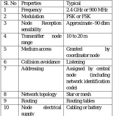
[image:5.612.48.553.196.677.2]WSN for home automation systems contains certain characteristics that are linked intrinsically with their application, such as command and control capability, low cost, low data rate, extremely reduced energy consumption, capacity to interconnect with other networks, average delays superiors 100ms, self-organization capability.The table 1 below, presents the typical characteristics of a WSN for the home automation.
Table 1. Characteristic of WSN for home automation
Sl. No Properties Typical
1 Frequency 2.4 GHz or 900 MHz
2 Modulation PSK or FSK
3 Node Reception
sensibility
Approximate -90 dbm
4 Transmitter node
range
10 to 20 m
5 Medium access Granted by
coordinator node
6 Collision avoidance Listening
7 Addressing Assigned by central
node (including
network identification code)
8 Network topology Star or mesh
9 Routing Routing tables
10 Node electrical
supply
Cabling or battery
C. Components of Sensor Node
[image:5.612.189.423.209.450.2]Technology (IJRASET)
©IJRASET 2013: All Rights are Reserved
565
1) Sensing Unit: Sensing units are usually composed of two subunits: sensors and analog to digital converters (ADCs). Sensors can be classified as either analog or digital devices. There exists a variety of sensors that measure environmental parameters such as temperature, light intensity, sound, magnetic fields, image, etc. The analog signals produced by the sensors based on the observed phenomenon are converted to digital signals by the ADC and then fed into the processing unit.
2) Processing Unit: The processing unit mainly provides intelligence to the sensor node. The processing unit consists of a microprocessor, which is responsible for control of the sensors, execution of communication protocols and signal processing algorithms on the gathered sensor data. Commonly used microprocessors are Intel's Strong ARM microprocessor, Atmel‘s AVR
microcontroller and Texas Instruments' MP430 microprocessor.The processing unit of μAMPS wireless sensor node prototype has a
59–206 MHz SA-1110 micro-processor. In general, four main processor states can be identified in a microprocessor: off, sleep, idle and active. In sleep mode, the CPU and most internal peripherals are turned on, and can only be activated by an external event (interrupt). In idle mode, the CPU is still inactive, but other peripherals are active.
D. Transceiver Unit
The radio enables wireless communication with neighbouring nodes and the outside world. It consists of a short range radio which usually has single channel at low data rate and operates at unlicensed bands of 868-870 MHz (Europe), 902-928 MHz (USA) or near 2.4 GHz (global ISM band). For example, the TR1000 family from RF Monolithics works in the 800–900 MHz range can dynamically change its transmission power up to 1.4 mW and transmit up to 115.2 Kbps. The Chipcon‘s CC2420 is included in the
MICAZ mote that was built to comply with the IEEE 802.15.4 standard [10] for low data rate and low cost wireless personal area
networks. There are several factors that affect the power consumption characteristics of a radio, which includes the type of modulation scheme used, data rate, transmit power and the operational duty cycle. Brian Otis, Jan Rabaey (2007) [14] stated that, at transmitted power levels of -10dBm and below, a majority of the transmit mode power is dissipated in the circuitry and not radiated from the antenna. However, at high transmit levels (over 0dBm) the active current drown by the transmitter is high. The transmit power levels for sensor node applications are roughly in the range of -10 to +3 dBm.
E. Battery
The sensor nodes can be powered from energy storage devices or by energy scavenging. The former technique employs a variety of tiny batteries made up of thin films of vanadium oxide and molybdenum oxide .The battery supplies power to the complete sensor node. It plays a vital role in determining sensor node lifetime. The amount of power drawn from a battery should be carefully monitored. Sensor nodes are generally small, light and cheap, the size of the battery is limited. AA batteries normally store 2.2 to 2.5 Ah at 1.5 V. However, these numbers vary depending on the technology utilized. For example, Zinc–air-based batteries have higher capacity in Joules/cm3 than lithium batteries. Alkaline batteries have the smallest capacity, normally around 1200 J/cm3. Furthermore, sensors must have a lifetime of months to years, since battery replacement is not an option for networks with thousands of physically embedded nodes. This causes energy consumption to be the most important factor in determining sensor node lifetime.
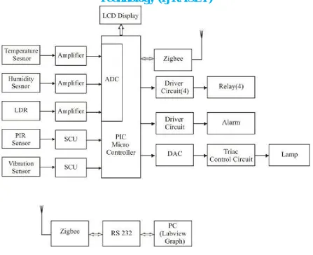
V. BLOCK DIAGRAM AND DESCRIPTION
Technology (IJRASET)
[image:7.612.84.531.70.434.2]©IJRASET 2013: All Rights are Reserved
566
Figure 2.Proposed system Block Diagram
A. Sensor Module
1) Temperature Sensor: A thermistor is a type of resistor used to measure temperature changes, relying on the change in its resistance with changing temperature. Thermistor is a combination of the words thermal and resistor. The Thermistor was first invented by Samuel Ruben in 1930, and has U.S. Patent #2,021,491. If we assume that the relationship between resistance and temperature is linear (i.e. we make a first-order approximation), then we can say that:
ΔR = kΔT - - - (1)
Technology (IJRASET)
[image:8.612.260.342.122.262.2]©IJRASET 2013: All Rights are Reserved
567
Figure 3.Thermistor Circuit
Circuit Description: In this circuit the thermistor is used to measure the temperature.Thermistor is nothing but temperature sensitive resistor. There are two type of thermistor available such as positive temperature co-efficient and negative temperature co- efficient. Here we are using negative temperature co-efficient in which the resistance value is decreased when the temperature increased. Here the thermistor is connected with resister bridge network. The bridge terminals are connected 16 to inverting and non-inverting input terminals of comparator. The comparator is constructed by LM 324 operational amplifier. The LM 324 consist of four independent, high gains, internally frequency compensated operational amplifier which were designed specifically to operate from a single power supply over a wide voltage range.
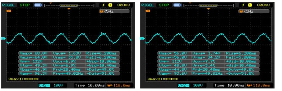
The first stage is a comparator in which the variable voltage due to thermistor is given to inverting input terminal and reference voltage is given to non-inverting input terminal. Initially the reference voltage is set to room temperature level so the output of the comparator is zero. When the temperature is increased above the room temperature level, the thermistor resistance is decreased so variable voltage is given to comparator. Now the comparator delivered the error voltage at the output. Then the error voltage is given to next stage of preamplifier. Here the input error voltage is amplified then the amplified voltage is given to next stage of gain amplifier. In this amplifier the variable resistor is connected as feedback resistor. The feedback resistor is adjusted to get desired gain. Then the AC components in the output are filtered with the help of capacitors. Then output voltage is given to final stage of DC voltage follower through this the output voltage is given to ADC or other circuit. The following fig 4.2 shows temperature
sensor DSO output readings.
[image:8.612.74.538.549.699.2]Technology (IJRASET)
©IJRASET 2013: All Rights are Reserved
568
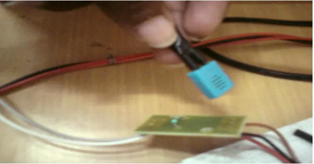
[image:9.612.90.539.231.379.2]2) Humidity Sensor: Humidity is the amount of water vapor in an air sample. There are three different ways to measure humidity: absolute humidity, relative humidity, and specific humidity. Relative humidity is the most frequently encountered measurement of humidity because it is regularly used in weather forecasts. It‘s an important part of weather reports because it Indicates the likelihood of precipitation, dew, or fog. Higher relative humidity also makes it feel hotter outside in the summer because it reduces the effectiveness of sweating to cool the body by preventing the evaporation of perspiration from the skin. This effect is calculated in a heat index table. Warmer air has more thermal energy than cooler air; thus more water molecules can evaporate and stay in the air in a vapour state rather than a liquid state. This may be why people say that warmer air "holds" more moisture — in warmer air, there is more energy for more water molecules to hold themselves in the air .
Figure.5 Humidity Sensor circuit
Circuit Description :This circuit is designed to measure the humidity level in the atmosphere air. The humidity sensor is used for the measurement device. The humidity sensor is consists of astable mulitivibrator in which the capacitance is varied depends on the humidity level. So the multivibrators produce the varying pulse signal which is converted into corresponding voltage signal.The voltage signal is given to inverting input terminal of the comparator. The reference voltage is given to non inverting input terminal. The comparator is designed by the LM 741 operational amplifier.The comparator is compared with reference humidity level and delivered the corresponding error voltage at its output which is given to next stage of gain amplifier in which the variable resistor is connected in the feedback path by adjusting the resistor we can get the desired gain. Then the final voltage is given to microcontroller or other circuit in order to find the humidity level in the atmosphere. Fig 4.4 shows Humidity sensor .
[image:9.612.145.469.515.684.2]Technology (IJRASET)
©IJRASET 2013: All Rights are Reserved
569
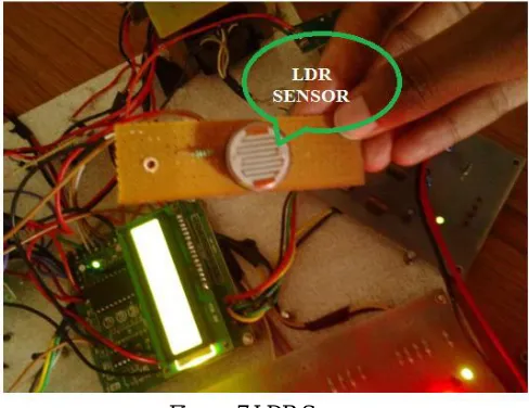
[image:10.612.184.428.119.307.2]3) LDR Light Dependent Resistor - LDR: Two cadmium sulphide (cds) photoconductive cells with spectral responses similar to that of the human eye. The cell resistance falls with increasing light intensity. Applications include smoke detection, automatic lighting control, and batch counting.
Figure. 7 LDR Sensor
Fig 4.8(a) Motion Detection Fig 4.8(b) No Motion Detection
PIR The pyroelectric sensor is made of a crystalline material that generates a surface electric charge when exposed to heat in the form of infrared radiation. When the amount of radiation striking the crystal changes, the amount of charge also changes and can then be measured with a sensitive FET device built into the sensor. The sensor elements are sensitive to radiation over a wide range so a filter window is added to the TO5 package to limit incoming radiation to the 8 to 14μm range which is most sensitive to human body radiation.
Working Operation
[image:10.612.152.526.342.526.2]Technology (IJRASET)
©IJRASET 2013: All Rights are Reserved
570
VI. RESULTS AND DISCUSSIONS
Home Automation is undeniably a resource which can make a home environment automated. People can control their electrical devices via these Home Automation devices and set up the controlling actions in the computer. This project address a new intelligent home control system based on active sensor networks to make home networks more intelligent and automatic.The proposed system has been implemented and related hardware and software are also developed. The new ubiquitous home scenarios based on the proposed system was suggested . To evaluate the effectiveness of our scheme, we performed simulations with the keil microvision simulator under various parameters. The parameters include the size of the house, the number of sensor nodes in the house, and applications. Sensors and communication devices used for the deployment in smart home are not required to have highspeed communication capacities; rather more consideration needs to be focused on a limited amount of delay in communication and a low energy consumption. Zigbee 802.15.4 which has been used as an interface between pic microcontroller and PC is for cost, low-rate and low-power consumption WSNs due to its flexibility to fulfill different requirements of various application patterns, by adequately tuning its parameters.
REFERENCES
[1] Sun, J. Z. Li, Y. Chen and H. S. Zhu, (2005), ‘Wireless Sensors Networks,’ Tsinghua University Press, Beijing.
[2] Willing A (2006), ‘Wireless Sensor Networks: Concept, Challenges and Approaches,, Elektrotechnik & Informationstechnik, Vol. 123, No.6, pp. 224-231.
[3] Adam C and W. Jakub, (2009), ‘On Applications of Wireless Sensor Networks,’ Internet - Technical Development and Applications, Springer, pp.91-99.
[4] Thomas S, D. F. Henri and V. Martin, (2005), ‘Sensor Scope:Experiences with a Wireless Building Monitoring Sensor Network,, Proceedings of the Workshop on Real-World Wireless Sensor Networks, Stockholm.
[5] Chang J. Y., J. Y. Kim and O. Kwon, (2009) “Demo Abstract: Control City – Integrating Wireless Sensor Networks and Building Management Systems,” Proceedings of the International Conference on Information Processing in Sensor Networks. San Francisco, pp.421-422.
[6] Jang W. S., W. M. Healy and J. S. Miroslaw, (2008), ‘Wireless Sensor Networks as Part of a Web-Based Building Environmental Monitoring System,’ Automation in Construction,Vol. 17, No. 6, pp. 729-736..
[7] Tessa D., G. Elena and B. James, (2009), ‘Wireless Sensor Networks to Enable the Passive House- Deployment Experiences,’ Smart Sensing and Context, Berlin Heidelberg:Springer, pp. 177-192.
[8] Akylidiz I. F., W. L. Su, Y. Sankarasubramaniam and E. Cayirci, (2002), “Wireless Sensor Networks: A Survey on Sensor Networks,” IEEE Communications Magazine, Vol. 40, No. 8, pp. 102-114.
[9] Venkata Reddy Adama, (2010), ‘Wireless Sensor Network Architecture for Smart Buildings, published by Jyothishmathi Institute of Technology & Science, India.
[10]IEEE Standard 802.15.4, (2006), "Wireless Medium Access Control (MAC) and Physical Layer (PHY) Specifications for Low-Rate Wireless Personal Area Networks (LR-WPANs),".
[11]Andrew Wheeler, (2007), "Commercial Applications of Wireless Sensor Networks Using ZigBee," Communication Magazine, IEEE, vol. 45, pp. 70-77, April 2007.
[12]Kothari. C.R., (2004), ‘Research Methodology’, published by New Age International Publishers, New Delhi, p.219.
[13]Michal Varchola, Miloš Drutarovský, (2007) "ZigBee Based Home Automation Wireless Sensor Network,” Acta Electrotechnica et Informatica No. 4, Vol. 7, 2007.
[14]Brian Otis, Jan Rabaey, (2007), ‘Ultra-Low Power Wireless Technologies for Sensor Networks.: Springer.
[15]ZigBee Alliance, "ZigBee home automation puplic application profile,”revision 25,v.1.0,Oct.2007