6
I
January 2018
Design of the 16-bit Vedic Multiplier Based on
Compressor Adder
Harshit Swaroop1
1
Department of Electronics & Communication, SIET, Allahabad
Abstract: This paper proposed the design of 16 bit Multiplier using the techniques of Ancient Indian Vedic Mathematics that have been modified to improve performance. Vedic Mathematics is the ancient system of mathematics which has a unique technique of calculations based on 16 Sutras. The work has proved the efficiency of Urdhva tiryakbhyam – Vedic method for multiplication which strikes a difference in the actual process of multiplication itself. It enables parallel generation of intermediate products, eliminates unwanted multiplication steps with zeros and scaled to higher bit levels. So the design complexity gets reduced for inputs of larger no of bits and modularity gets increased. The adders used for partial product sum generation are the major power consuming elements. In our design we can optimize the adder design for minimizing the power consumption. We have proposed the low power adder design using compressor adders. The proposed Vedic multiplier is coded in VHDL (Very High Speed Integrated Circuits Hardware Description Language), synthesized and simulated using EDA (Electronic Design Automation) tool – Xilinx9.1.
Keywords: Vedic Multiplier, VHDL, sutras, Urdhva tiryakbhyam, multiplication, compressor adders
I. INTRODUCTION
Vedic mathematics is the name given to the ancient system of mathematics, or, to be precise, a unique technique of calculations based on simple rules and principles with which any mathematical problem can be solved – be it arithmetic, algebra, geometry or trigonometry. The system is based on 16 Vedic sutras or aphorisms, which are actually word formulae describing natural ways of solving a whole range of mathematical problems. Vedic mathematics was rediscovered from the ancient Indian scriptures between 1911 and 1918 by Sri Bharati Krishna Tirthaji (1884- 1960), a scholar of Sanskrit, mathematics, history and philosophy [1]. He studied these ancient texts for years and, after careful investigation, was able to reconstruct a series of mathematical formulae called sutras. Bharati Krishna Tirthaji, who was also the former Shankaracharya (major religious leader) of Puri, India, delved into the ancient Vedic texts and established the techniques of this system in his pioneering work, Vedic Mathematics (1965), which is considered the starting point for all work on Vedic mathematics. According to Mahesh Yogi, The sutras of Vedic Mathematics are the software for the cosmic computer that runs this universe. A great deal of research is also being carried out on how to develop more powerful and easy applications of the Vedic sutras in geometry, calculus and computing. Conventional mathematics is an integral part of engineering education since most engineering system designs are based on various mathematical approaches. The need for faster processing speed is continuously driving major improvements in processor technologies, as well as the search for new algorithms. A multiplier is one of the key hardware blocks in most digital signal processing systems. With advances in technology, many researchers have tried to design multipliers which offer either of the following- high speed, low power consumption, regularity of layout and hence less area or even combination of them in multiplier. The Vedic mathematics approach is totally different and considered very close to the way a human mind works. In this work, we try to present multiplication operations and the implementation of these using both conventional, as well as Vedic mathematical methods in VHDL language [1].
II. VEDICMATHEMATICS
Vedic mathematics is part of four Vedas (books of wisdom). It is part of Sthapatya- Veda (book on civil engineering and architecture), which is an upa-veda (supplement) of Atharva Veda. It gives explanation of several mathematical terms including arithmetic, geometry (plane, co-ordinate), trigonometry, quadratic equations, factorization and even calculus.
characteristics, Vedic maths has already crossed the boundaries of India and has become an interesting topic of research abroad. Vedic maths deals with several basic as well as complex mathematical operations. Especially, methods of basic arithmetic are extremely simple and powerful. The word “Vedic” is derived from the word “Veda” which means the store-house of all knowledge. Vedic mathematics is mainly based on 16 Sutras (or aphorisms) dealing with various branches of mathematics like arithmetic, algebra, geometry etc. These Sutras along with their brief meanings are enlisted below alphabetically.
A. (Anurupye) Shunyamanyat – If one is in ratio, the other is zero.
B. Chalana-Kalanabyham – Differences and Similarities.
C. Ekadhikina Purvena – By one more than the previous One.
D. Ekanyunena Purvena – By one less than the previous one.
E. Gunakasamuchyah – The factors of the sum is equal to the sum of the factors.
F. Gunitasamuchyah – The product of the sum is equal to the sum of the product.
G. Nikhilam Navatashcaramam Dashatah – All from 9 and last from 10.
H. Paraavartya Yojayet – Transpose and adjust.
I. Puranapuranabyham – By the completion or noncompletion.
J. Sankalana- vyavakalanabhyam – By addition and by subtraction.
K. Shesanyankena Charamena – The remainders by the last digit.
L. Shunyam Saamyasamuccaye – When the sum is the same that sum is zero.
M. . Urdhva-tiryagbhyam – Vertically and crosswise.
N. Vyashtisamanstih – Part and Whole.
O. Yaavadunam – Whatever the extent of its Deficiency.
III. CONVENTIONALADDERSDESIGN
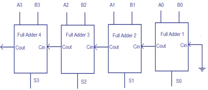
[image:3.612.138.493.382.535.2]A. Ripple Carry Adder
Fig. 1 Ripple Carry adder logic design
Multiple full adder circuits can be cascaded in parallel to add an N-bit number. For an N- bit parallel adder, there must be N number of full adder circuits. A ripple carry adder is a logic circuit in which the carry-out of each full adder is the carry in of the succeeding next most significant full adder. It is called a ripple carry adder because each carry bit gets rippled into the next stage. In a ripple carry adder the sum and carry out bits of any half adder stage is not valid until the carry in of that stage occurs. Propagation delay inside the logic circuitry is the reason behind this. Propagation delay is time elapsed between the application of an input and occurance of the corresponding output.
B. Carry Look Ahead adder
Fig. 2 Carry Look Ahead adder logic design
IV. PROPOSEDDESIGN
A. Compressor Adders Design
1) 5-3 Compressor:maximum value 101 is obtained. The circuit is reorganized in such away that only 3 XOR operations are used instead of 5XOR operations (in case of conventional 5-3 compressor) and other two inputs (X3 and X4) acts as a control signals.
2) 10-4 Compressor: Its circuitry takes ten inputs, adds the m and gives four bit output. The maximum resultant can be 1010. It makes use of two 5-3 compressors, two full adders and a half adder at the required position. Because of the use of modified 5-3 compressor circuitry, this compressor shows lesser delay and gate counts making the multiplier fast.
3) 15-4 Compressor: Its circuitry contains two5-3 compressors, five full adders and one 4bit parallel adder. The inputs are given in a group of three to the five full adders. Then the sum bits of all five full adder are added using one5-3 compressor and the carry bits of the full adders are fed to another 5-3 compressor. \
4) 20-5 Compressor: In the proposed design we need to add 19 bits at the same time and so need to use a higher compressor adder circuit. In 20-5 compressor circuit, it converts 20 partial products into five output bits having maximum value of 10010. This makes use of one 15-4 compressor, one 5-3 compressor, two half-adders and two full adders.
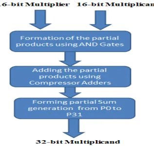
Fig.3 Flow Chart of the proposed algorithm
Multiplier: x31-x0
Multiplicand: y31 – y0
P0=x0y0--- (1)
P1=x1y0 + x0y1 (carry c1) ---(2)
[image:4.612.226.384.450.600.2]P3= x3y0 + x2y1 + x1y2 + x0y3 +c2 (carry c4, c5)--- (4)
P4=x4y0 + x3y1 + x2y2 + x1y3 + x0y4 + c3 + c4 (Carry c6, c7) --- (5)
P5=x5y0 + x4y1 + x3y2 + x2y3 + x1y4 + x0y5 + c5 +c6 (carry c8, c9, c10) --- (6)
P6=x6y0 + x5y1 + x4y2 + x3y3 + x2y4 + x1y5 + x0y6 + c7 + c8 (carry c11, c12, c13) --- (7)
P7=x7y0 + x6y1 + x5y2 + x4y3 + x3y4 + x2y5 + x1y6 + x0y7 + c9 + c11 (Carry c14, c15, c16) --- (8)
P8=x8y0 + x7y1 + x6y2 + x5y3 + x4y4 + x3y5 + x2y6 + x1y7 + x0y8 + c10 + c12 + c14 (Carry c17,c18,c19) --(9)
P9=x9y0 + x8y1 + x7y2 + x6y3 + x5y4 + x4y5 + x3y6 + x2y7 + x1y8 + x0y9 + c13 + c15 + c17 (carry c20, c21, c22) ---(10)
P10=x10y0 + x9y1 + x8y2 + x7y3 + x6y4 + x5y5 + x4y6 + x3y7 + x2y8 + x1y9 + x0y10 + c16 + c18 + c20 (carry c23, c24, c25) ---(11)
P11=x11y0 + x10y1 + x9y2 + x8y3 + x7y4 + x6y5 + x5y6 + x4y7 + x3y8 + x2y9 + x1y10 + x0y11 + c19 + c21 + c23 (carry c26, c27, c28) --- (12)
P12=x12y0 + x11y1 + x10y2 + x9y3 + x8y4 + x7y5 + x6y6 + x5y7 + x4y8 + x3y9 + x2y10 + x1y11 + x0y12 + c22 + c24 + c26 (carry c29, c30, c31, c32) --- (13)
P13=x13y0 + x12y1 + x11y2 + x10y3 + x9y4 + x8y5 + x7y6 + x6y7 + x5y8 + x4y9 + x3y10 + x2y11 + x1y12 + x0y13 + c25 + c27 + c29 (carry c33, c34, c35, c36) --- (14)
P14=x14y0 + x13y1 + x12y2 + x11y3 + x10y4 + x9y5 + x8y6 + x7y7 + x6y8 + x5y9 + x4y10 + x3y11 + x2y12 + x1y13+ x0y14 + c28 + c30 + c33(carry c37,c38,c39,c40) --- (15)
P15=x15y0 + x14y1 + x13y2 + x12y3 + x11y4 + x10y5 + x9y6 + x8y7 + x7y8 + x6y9 + x5y10 + x4y11 + x3y12 + x2y13 + x1y14 + x0y15 + c31 + c34 + c37 (carry c41,c42,c43,c44) --- (16)
P16=x15y1 + x14y2 + x13y3 + x12y4 + x11y5 + x10y6 + x9y7 + x8y8 + x7y9 + x6y10 + x5y11 + x4y12 + x3y13 + x2y14 + x1y15 + c32 + c35 + c38 + c41 (carry c45,c46,c47,c48) --- (17)
P17=x15y2 + x14y3 + x13y4 + x12y5 + x11y6 + x10y7 + x9y8 + x8y9 + x7y10 + x6y11 + x5y12 + x4y13 + x3y14 + x2y15 + c36 + c39 + c42 + c45 (carry c49, c50, c51, c52) (18)
P18=x15y3 + x14y4 + x13y5 + x12y6 + x11y7 + x10y8 + x9y9 + x8y10 + x7y11 + x6y12 + x5y13 + x4y14 + x3y15 + c40 + c43 + c46 + c49 (carry c53, c54, c55, c56) --- (19)
P19=x15y4 + x14y5 + x13y6 + x12y7 + x11y8 + x10y9 + x9y10 + x8y11 + x7y12 + x6y13 + x5y14 + x4y15 + c44 + c47 + c50 + c53 (carry c57, c58, c59, c60) ---- (20)
P20=x15y5 + x14y6 + x13y7 + x12y8 + x11y9 + x10y10 + x9y11 + x8y12 + x7y13 + x6y14 + x5y15 + c48 + c51 + c54 + c57 (carry c61, c62, c63,) --- (21)
P21=x15y6 + x14y7 + x13y8 + x12y9 + x11y10 + x10y11 + x9y12 + x8y13 + x7y14 + x6y15 + c52 + c55 + c58 + c61 (carry c64, c65, c66) --- (22)
P22=x15y7 + x14y8 + x13y9 + x12y10 + x11y11 + x10y12 + x9y13 + x8y14 + x7y15 + c56 + c59 + c62 + c64 (carry c67, c68, c69) --- (23)
P23=x15y8 + x14y9 + x13y10 + x12y11 + x11y12 + x10y13 + x9y14 + x8y15 + c60 + c63 + c65 + c67 (carry c70, c71, c72) ---- (24) P24= x15y9 + x14y10 + x13y11 + x12y12 + x11y13 + x10y14 + x9y15 + c66 + c68 + c70 (carry c73, c74, c75) (25) P25= x15y10 + x14y11 + x13y12 + x12y13 + x11y14 + x10y15 + c69 + c71 + c73 (carry c76, c77, c78) --- (26)
P27= x15y12 + x14y13 + x13y14 + x12y15 + c75 + c77 + c79 (carry c82, c83) --- (28)
P28= x15y13 + x14y14 + x13y15 + c78 + c80 + c82 (carry c84, c85) --- (29)
P29= x15y14 + x14y15 + c81 + c83 +c84 (carry c86) ---(30)
P30=x15y15 + c85 + c86 (carry c87) --- (31)
P31=c87 --- (32)
[image:6.612.183.428.188.304.2]V. RESULTS&DISCUSSIONS
Fig. 4 RTL structure of the proposed design
Figure 4 shows the RTL structure of the block of the proposed vedic multipler (16-bit). The RTL structure in the designed logic represents 16-bit inputs a and b. Similarly, the output is 32 bit output data. The resultant is obtained by the multiplication process of both the inputs.
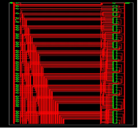
Fig. 5 Detailed RTL structure of the proposed design
Figure 5 shows the detailed RTL structure of the proposed design. The designed structure contains the 32 different sum products the resultant bits. Each block represents the logic structure required for implementation of the Compressor
adders.
Figure 6, shows the simulation resultant of the proposed design. a(15:0) = 0000000000000011
[image:6.612.188.427.373.598.2]Fig. 6 Simulation result of the proposed design
A. Resultant:
Data_out(31:0) = 0000000000000000000000000001001 In case 2
Inputs:
a(15:0) = 0000000000000111 b(15:0) = 0000000000000011 Resultant:
Data_out(31:0) = 0000000000000000000000000010101
Fig.7 Power consumption report
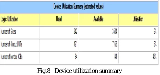
Fig.8 Device utilization summary
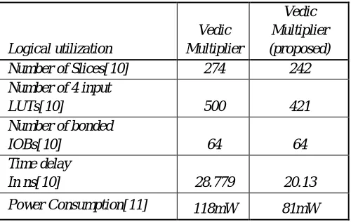
[image:7.612.175.439.547.672.2]Table 1. Comparison chart of proposed design
In table 1, we presented the comparison chart. Thus, here we found that the proposed design have lowered the delay, optimized the utilization of the device. Thus, our delay has been reduced significantly and power consumption has been reduced significantly.
VI. CONCLUSION
Thus, in this work we have presented the design of the low power edic multiplier design using power efficient compressor adders and delay reduction. We have thus presented the algorithm of the vedic multiplier and thus all the partial sum generated are being added by the proposed compressor adders. Thus, our proposed design has been shown to work effectively generating multiplication of two 16-bit numbers.
REFERENCES
[1] Jagadguru Swami Sri Bharati Krisna Tirthaji Maharaja, “Vedic Mathematics: Sixteen Simple Mathematical Formulae from the Veda,” Motilal Banarasidas Publishers, Delhi, 2009, pp. 5-45
[2] Virendra Babanrao Magar, “Intelligent and Superior Vedic Multiplier for FPGA Based Arithmetic Circuits”, International Journal of Soft Computing and Engineering (IJSCE) ISSN: 2231-2307, Volume-3, Issue-3, July 2013
[3] A. D. Booth, “A signed binary multiplication technique,” Q. J. Mech.Appl. Math., vol. 4, pp. 236–240, 1951.
[4] .S.S.Kerur, Prakash Narchi, Jayashree C N, Harish M Kittur and Girish V A “Implementation of Vedic Multiplier for Digital Signal Processing” International conference on VLSI communication & instrumentation (ICVCI), 2011.
[5] Mr. Dharmendra Madke, Assoc. Prof. Sameena Zafar “Review Paper on High Speed Karatsuba Multiplier and Vedic Mathematics Techniques” International Journal of Advanced Research in Computer Science and Software Engineering, Volume 3, Issue 12, December 2013
[6] B. Krishna ,P. Siva Durga Rao, N. V. G. Prasad “High Speed and Low Power Design of Parallel Prefix Adder”International Journal of electronics & communication technology ,Volume 3, Issue 4,October-December 2012.
[7] Sumit Vaidya and Deepak Dandekar “Delay-power performance Comparison of multipliers in VLSI Circuit design” International Journal of Computer Networks & Communications (IJCNC), Volume 2, No.4, July 2010.
[8] Diptendu Kumar Kundu, Supriyo Srimani, Saradindu Panda, Prof. Bansibadan Maji “Implementation of Optimized High Performance 4x4 Multiplier using Ancient Vedic Sutra in 45 nm Technology” 2014 2nd International Conference on Devices, Circuits and Systems (ICDCS), 978-1-4799-1356-5/14/$31.00 ©2014 IEEE.
[9] Gaurav Sharma , Arjun Singh Chauhan , Himanshu Joshi , Satish Kumar Alaria “Delay Comparison of 4 by 4 Vedic Multiplier based on Different Adder Architectures using VHDL” International Journal of IT, Engineering and Applied Sciences Research (IJIEASR), Volume 2, No. 6, June 2013.
[10] S.P.Pohokar, R.S.Sisal, K.M.Gaikwad, M.M.Patil, Rushikesh Borse, “Design and Implementation of 16 x 16 Multiplier Using Vedic Mathematics”, IEEE, ICIC, 2015
[11] Ch. Harish Kumar, “Design and Implementation of 16 x 16 Multiplier Using Vedic Mathematics”, International Journal of Scientific and Research Publications, January 2013
Logical utilization Vedic Multiplier Vedic Multiplier (proposed)
Number of Slices[10] 274 242
Number of 4 input
LUTs[10] 500 421
Number of bonded
IOBs[10] 64 64
Time delay
In ns[10] 28.779 20.13