6
I
January 2018
Effect of Process Parameters of Tungsten Inert Gas
Welding on Welding of Duplex Stainless Steels
A.Balaram Naik 1, A.Chennakesava Reddy 2, V.Venugopal Reddy3
1
Asst professor of Dept. of Mechanical Engineering, JNTUH College of Engineering, Hyderabad, Kukatpally
2
Professor Dept. of Mechanical Engineering, JNTUH College of Engineering, Hyderabad, Kukatpally
3
MTECH student of Dept. of Mechanical Engineering, JNTUH College of Engineering, Hyderabad, Kukatpally
Abstract: Welding input parameters play a very significant role in determining the quality of a weld joint. The joint quality can be defined in terms of mechanical properties such as ultimate tensile strength, hardness and toughness. Generally, all welding processes are used with the aim of obtaining a welded joint with the desired mechanical properties with minimum distortion. The present work deals with optimization of tungsten inert gas welding process on Duplex Stainless Steel(DSS 2304).Taguchi L9 orthogonal array method was employed to optimize the welding process parameters of DSS-2304 weld for improvement of mechanical properties of weld bead such as Tensile strength, Hardness , Toughness. Four variable welding parameters and their three levels were selected and design of experiments (DOE) was implemented as per Taguchi L9 orthogonal array. The present analysis is to find out the best influence of welding current, welding speed, welding position and filler material on mechanical properties.
Keywords: Tungsten Inert Gas Welding, Mechanical Properties, Taguchi technique and Duplex Stainless Steel
I. INTRODUCTION
Duplex Stainless steel DSS typically comprises of microstructure consisting approximately equal proportion of ferrite(δ) and austenite (γ).DSS is a commonly used structural material in the oil, gas ,manufacturing industries and has special application in chemical ,wastewater, marine engineering field.
1) Gagandeep Singh has investigated the Mechanical Properties for TIG Welding at Different Parameters with and without use of Flux and concluded that hardness of weld metal decreased with increase in current, voltage and gas flow rate. Because due to increase in current, voltage and gas flow rate the heat input and arc length increased, hence hardness decreased. He concluded that hardness of weld metal increased with increase in diameter of electrode, because due to increase in diameter of electrode the heat affected zone will increase hence hardness increases. It also concluded that hardness of weld metal is less in case of welding without flux as compare to welding with flux.
2) Ahmed Khalid, Paramesh. T have conducted TIG welding by varying welding speed (0.3, 0.6, 0.9, 1.2 cm/sec) and bevel angle in degrees (30, 40, 50, and 60). They concluded that tensile strength is maximum for low speed welding (0.3 cm/sec) and for bevel angle in range of 30-45
3) Sreehari R. nair has conducted TIG welding on duplex stainless steel material to find optimum parameters of welding. They concluded that optimum parameters for TIG welding on duplex stainless steel material are 1mm gap between electrodes and weld velocity 130mm/min, current 140amps and voltage of 12 volts
4) Surjeet singh has conducted TIG welding on aluminium. He concluded that out of two filler rods the 4043 material AA6082. By taking specimen dimensions as 220*40*6 (dimensions in mm) , bevel height 1.5mm ,bevel angle 30 degrees ,root gap 1mm. the input parameters current (80amps, 100amps, 120amps) ,gas flow rate (8, 10, 12 LPM) and filler rods used are Al4043 and Al4047. They performed tensile test and concluded that in increase in current and gas flow rate increases tensile strength of weld have offered more tensile strength than weld joint made of 4047
5) Vedprakashsingh has done TIG welding on SS304 specimen they varied input factors welding current (150, 175, 200 amps), groove angle (45, 60, 75 degrees), and speed (2, 2.5, 3 mm/sec).they used design of experiments method for experimental design and ANOVA analysis. They concluded that the percentage contribution of current is 52.67%, groove angle is 15.18% and welding speed is 28.52% on distortion in TIG welding
parameters during machining. He concluded that according to the order of importance, the parameters affecting the penetration, tensile strength and hardness are: Welding current and filler wire diameter. The optimum process parameters for TIG welding of SS 304 steels are found to be: Wire Diameter = 3 mm Welding Current = 140 Ampere
7) S A Patil made an attempt for optimization of process parameters for enhancing welding penetration in activated flux coated tungsten inert gas welding. During his study they investigated that the optimum parameters for enhancing weld penetration for AISI304 steel plate 100mm*70mm*5mm* are obtained, when current is 175amp, Gas flow rate is 12.5 litter per minute, welding speed 1.6mm/second.
8) S.s sathe, M. sharne From there experimentation it is conclude that the optimization of welding process parameter for increasing Tensile Strength is obtained with SiO2 Activated flux powder. When welding current at 175 amps, Gas flow rate at 15 LPM, & welding speed at 6.66 mm/sec.
9) N. Karunakaran did an investigation to compare the mechanical properties and welding profiles of TIG welded aluminium alloy joints. The effects of pulsed current on tensile strength, hardness, and microstructure and stress distribution were reported. The parameters were welding current (55-75) A. voltage (11-13.5) V and a constant welding speed was used. From the experiment it is found that pulsed welding current improve the tensile behaviour of the weld compared with continuous current welding due to grain refinement occurring in the fusion zone.
10) Ahmet Durgutlu in his experimental investigation of the effect of hydrogen in argon as a shielding gas on TIG welding of stainless steels material by changing the parameters, Shielding gas 1.5%H2–Ar, 5%H2–Ar and pure Argon. Tensile strength and Penetration on plate specimen have dimensions 200*80*4 mm. They concluded the shielding gas of 1.5%H2–Ar sample weld has the highest tensile strength. And it can be observed that increasing hydrogen content in the shielding gas reduces the mechanical properties.
11) S. P. Gadewar in his experimental investigations of weld characteristics for a single pass TIG welding with SS304 using the specimen of 100L* 25w * (1, 2 and 3) thickness of welding plate. They used the input parameters of Welding current (15-180 Amp), Shielding Gas Flow (1-18 LPM), Work Piece thickness (1-3mm) and used the Regression analysis technique. And the final result of it is observed that as thickness of the work piece increases the Front width and Back width value across the weld also increases.
II. MATERIALANDMETHODOLOGY
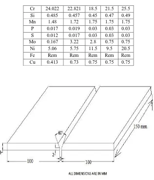
The tungsten inert gas Welding (TIGW) was used for welding of 2304 duplex stainless steel (DSS) plates of 150 mm x 100 mm x 6 mm plate dimensions. The welding process parameters which could influence the mechanical properties were selected to be weld current, weld time, Electrode Material and position of welding. The materials for filler rods were 316 L, 308L and 310 L. The chemical composition of the base metal and filler rods are given in table 1. The weld joint design is shown in figure 1. The experiments were conducted using arc gap 2 mm, V-groove angle of 60o, root gap of 3 mm. The direct current electrode negative DCEN (Straight polarity) was employed during TIG welding process.
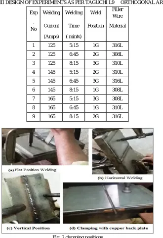
The Taguchi optimization method was selected to maximize the mechanical properties of welded bead. The four variable parameter Welding Current, Welding Time, Welding Position, Filler Material and their three levels were selected, the TIGW process parameter are given in the Table II. The two plates were held as per the design using C-Clamping fixtures for the flat, horizontal and vertical position of welding with 3 mm root gap between the welding plates as shown in figure 2. A grooved copper back up plate having dimensions 2mm x 5mm was fixed below the welding plates to avoid the flow-off of weld metal from the weld joint. The electrode diameter used was 3 mm for all experiments. Two and half electrode was consumed for each 150 mm weld length.
TABLE I
BASE MATERIAL AND FILLER MATERIAL COMPOSITION
Fig. 1 Weld joint design (Edge preparation).
TABLE II
TIG WELDING PROCESS PARAMETER AND THREE LEVELS
S.N O
Process parameters
Uni t
Leve
l 1 Level 2 Leve
l 3
1 Welding current
Am p
125a
mp 145amp 165a
mp
2 Welding time
Mi n
5:15
min 6:45min 8:15
min
3 Welding
position - flat
Horizon tal
verti cal
4 Filler rod material -
ER 316L
ER 308L
[image:4.612.169.435.453.729.2]TABLE III DESIGN OF EXPERIMENTS AS PER TAGUCHI L9 ORTHOGONAL ARRAY
Exp Welding Welding Weld Filler Wire .
No Current Time Position Material (Amps) ( mints)
1 125 5:15 1G 316L
2 125 6:45 2G 308L
3 125 8:15 3G 310L
4 145 5:15 2G 310L
5 145 6:45 3G 316L
6 145 8:15 1G 308L
7 165 5:15 3G 308L
8 165 6:45 1G 310L
9 165 8:15 2G 316L
Fig. 2 clamping positions
After conducting nine welding processes as per DOE, the experiments were carried out to measure the tensile strength, hardness, toughness by using UTM, Vickers hardness test and universal pendulum impact testing machine respectively in a bead on welded plates.
III. EXPERIMENTAL A. Tensile strength test
.
Fig. 3Tensile test specimens
B. Vickers Hardness Test
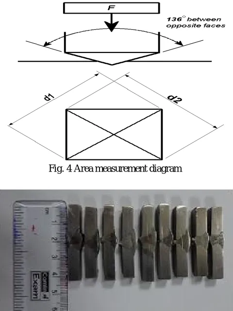
The Vickers hardness test is conducted by indenting the test material with a diamond indenter which is in the form of a right pyramid with a square base and an angle of 136 degrees between opposite faces subjected to a load of 50 gramforce. The full load is applied perpendicularly to the surface for 15 seconds. The two diagonals of the indentation left in the surface of the material after removal of the load are measured using a microscope and their average is calculated. The area of the sloping surface of the indentation is calculated. The Vickers hardness is obtained by dividing the kgf load by the area of indentation.
Vickers hardness formule
HV= (2Fsin (136o/2)/d2); HV=1.854(F/d2)
d = Arithmetic mean of the two diagonals, d1 and d2 in mm; HV = Vickers hardness; F= load in kgf.
[image:6.612.167.447.75.237.2]Fig. 4Area measurement diagram
[image:6.612.188.428.393.713.2]C. Impact Test
two kinds of specimens used for impact testing are known as Charpy and Izod. Both test pieces are broken in an impact testing machine. The only difference is in the manner that they are anchored. The Charpy piece is supported horizontally between two anvils and the pendulum strikes opposite the notch. The Izod piece is supported as a vertical cantilever beam and is struck on the free end projecting over the holding vise.
[image:7.612.187.425.203.514.2]A Charpy test measures the welds ability to withstand an Impact force. Low Charpy test readings indicate brittle weld metal Higher Charpy readings indicate the samples toughness. The toughness values of the weld-pieces are tabulated above. Weld-pieces are placed at the impact testing machine as simply supported. The hammer of the heavy weight is then released and corresponding values of weight provides the toughness values for weld-pieces
Fig. 6 Impact testing machine
Fig. 7 Impact test specimen
[image:7.612.84.524.551.741.2]IV. EXPERIMENTAL RESULTS
Table iv
Experimental data of l9 taguchi orthogonal array, process parameters and corresponding response parameters values Exp.No. Process parameters Response parameters
welding current
(amp)
welding time(min)
welding position
filler wire material
ultimate tensile strength
vickers hardness
impact energy
V. TAGUCHIANALYSIS
TABLE V DESIGN SUMMARY
Taguchi
array L9(3^4) Factors: 4 Runs: 9
[image:8.612.248.363.95.170.2]A. Ultimate tensile strength versus welding current, welding time, welding position and filler wire material
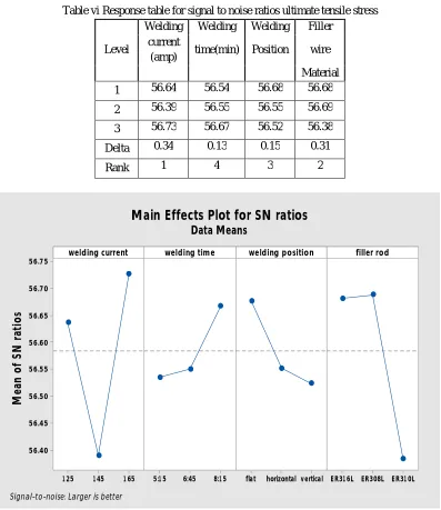
Table vi Response table for signal to noise ratios ultimate tensile stress
Level
Welding Welding Welding Filler current
(amp) time(min) Position wire Material 1 56.64 56.54 56.68 56.68
2 56.39 56.55 56.55 56.69
3 56.73 56.67 56.52 56.38
Delta 0.34 0.13 0.15 0.31
Rank 1 4 3 2
1 65 1 45 1 25
56.75
56.70
56.65
56.60
56.55
56.50
56.45
56.40
8:1 5 6:45
5:1 5 flat horizontalvertical ER31 6L ER308L ER31 0L
welding current
M
e
a
n
o
f
S
N
r
a
ti
o
s
welding time welding position filler rod
Main Effects Plot for SN ratios
Data Means
Signal-to-noise: Larger is better
Fig. 8 Ultimate tensile stress
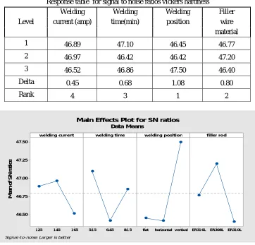
[image:8.612.108.505.201.660.2]B. Vickers hardness versus welding current, welding time, welding position and filler wire material Table vii
Response table for signal to noise ratios vickers hardness
Level
Welding Welding Welding Filler current (amp) time(min) position wire
material
1 46.89 47.10 46.45 46.77
2 46.97 46.42 46.42 47.20
3 46.52 46.86 47.50 46.40
Delta 0.45 0.68 1.08 0.80
Rank 4 3 1 2
1 65 1 45 1 25 47.50 47.25 47.00 46.75 46.50 8:1 5 6:45
5:1 5 flat horizontalv ertical ER31 6L ER308L ER31 0L
welding current M e a n o f S N r a ti o s
welding time welding position filler rod
Main Effects Plot for SN ratios
Data Means
Signal-to-noise: Larger is better
Fig. 9 Vicker hardness
It is observed that from table VII the order of effect of input process parameters are welding current, welding time, filler material and weding position. From Fig.9 the hardness is maximum when input parameters are welding current 145amps , welding time 5minutes 15 sec , vertical position and filler material is 308ER
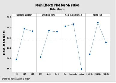
C. Impact energy versus welding current, welding time, welding position and filler wire material
Table viii
response table for signal to noise ratios for : impact energy
level
welding welding welding filler current
(amp) time(min) position wire material
1 36.44 36.56 38.06 36.70
2 37.94 37.84 38.16 38.23
3 37.82 37.79 35.97 37.26
Delta 1.50 1.28 2.19 1.53
1 65 1 45 1 25 38.5 38.0 37.5 37.0 36.5 36.0 8:1 5 6:45
5:1 5 flat horizontal vertical ER31 6L ER308L ER31 0L
welding current M e a n o f S N r a ti o s
welding time welding position filler rod
Main Effects Plot for SN ratios
Data Means
[image:10.612.115.500.79.357.2]Signal-to-noise: Larger is better
Fig. 10 Impact energy
It is observed that from table VIII the order of effect of input process parameters are welding time, welding current, filler materia and welding position. From Fig.10 the impact strength is maximum when input parameters are welding current 145amps , welding time 6minutes 45sec , horizonta position and filler material is 308ER
VI. CONCLUSION A. Ultimate tensile strength
The influence of weding current is minimum and welding time is maximum,. The maximum ultimate tensile strength is occurring for, when input parameters are welding current 165amps , welding time 8minutes 15sec , flat position and filler material is 308ER.
B. Hrdness
The influence of welding position on the hardness is minimum and welding current is maximum. The maximum hardness is occurring for, when input parameters are welding current 145amps , welding time 5minutes 15 sec , vertical position and filler material is 308ER.
C. Toughness
The influence of welding position on the impact energy is minimum and welding time is maximum. The maximum impact energy is occurring for, when input parameters are welding current 145amps , welding time 6minutes 45sec , horizonta position and filler material is 308ER.
REFERENCES
[1] Gagandeep Singh1, Fatehpal Singh2, Harwinder Singh,” A Study of Mechanical Properties on TIG Welding at Different Parameters with and without use of Flux”, International Journal of Technology Innovations and Research, Volume 16, July 2015.
[2] Ahmed Khalid Hussain, Abdul Lateef, MohdJaved, Paramesh.T,” Influence of Welding Speed on Tensile Strength of Welded Joint in TIG Welding Process”, INTERNATIONAL JOURNAL OF APPLIED ENGINEERING RESEARCH, Volume 1, No 3, 2010.
[3] G. Magudeeswaran, Sreehari R. Nair, L. Sundar et al, “Optimization of process parameters of the activated tungsten inert gas welding for aspect ratio of UNS S32205 duplex stainless steel welds”, Defences Technology, oct,2014.
[5] Vedprakash Singh, Vijay Patel, “EXPERIMENTAL INVESTIGATION OF GTAW FOR AUSTENITIC STAINLESS STEEL USING DOE”, International Journal For Technological Research In Engineering Volume 1, Issue 9, May-2014.
[6] Sreejith S Nair, “EXPERIMENTAL INVESTIGATION OF MULTIPASS TIG WELDING USING RESPONSE SURFACE METHODOLOGY”, international journal of mechanical engineering and robotics research, Vol. 2, No. 3, July 2013.
[7] S.A.Patil, “Optimisation of process Parameters for Enhancing Welding Penetration in Activated Flux Coated Tungsten Inert Gas Welding”, 3rd International Conference on Recent Trends in Engineering & Technology (ICRTET’2014).
[8] S. S. Sathe, M. S. Harne, “Optimization of Process Parameters in TIG Welding of Dissimilar Metals by Using Activated Flux Powder”, International Journal of Science and Research, 2013.
[9] Ahmet Durgutlu, “Experimental investigation of the effect of hydrogen in argon as a shielding gas on TIG welding of austenitic stainless steel”, Materials and Design, Vol.25, 2004.