Analysis of Counter Flow Heat Exchanger Using
Copper as A Material
B. Ramakrishna1, J. Pavan kumar2, B. Ramu3
123Assistant professor Mahatma Gandhi Institute of Technology Gandipet, HYD-500075, Telangana-India
Abstract: The general function of a heat exchanger is to transfer heat from one fluid to another. The basic component of a heat exchanger can be viewed as a tube with one fluid running through it and another fluid flowing by on the outside. The temperature gradient or the differences in temperature facilitate this transfer of heat. Transfer of heat happens by three principle means conduction, convection and radiation. In the use of heat exchangers radiation does take place. However, in comparison to conduction and convection, radiation does not play a major role. The objective of present work involves the study of refinery process and applies phenomena of heat transfer using copper as a material for thermal design of counter flow heat exchanger. The inner pipe in which hot hydrocarbon flows and in outer annulus cold crude oil passes from opposite direction. The heat recovery from hot fluid is used to increase the temperature of cold fluid. Design was carried out based on the outlet temperature requirement of the cold fluid. With the help of computation fluid dynamics the study and unsteady simulation carried out for designed heat exchanger and based on the simulation results thermal analysis carried out.
Keywords: Counter flow Heat exchanger, Distillation, CFD analysis
I. INTRODUCTION
In heat exchangers, heat transfer between fluids takes place through a separating wall or into and out of a wall in a transient manner. In many heat exchangers, the fluids are separated by a heat transfer surface, and ideally they do not mix or leak. Such exchangers are referred to as direct transfer type, or simply recuperates. In contrast, exchangers in which there is intermittent heat exchange between the hot and cold fluids via thermal energy storage and release through the exchanger surface or matrix are referred to as indirect transfer type, or simply regenerators. Such exchangers usually have fluid leakage from one fluid stream to the other, due to pressure differences and matrix rotation valve switching. Heat exchangers are commonly used in practice in a wide range of applications, from heating and air-conditioning systems in a household, to chemical processing and power production in large plants. Heat exchangers differ from mixing chambers in that they do not allow the two fluids involved to mix. In a car radiator, for example, heat is transferred from the hot water flowing through the radiator tubes to the air flowing through the closely spaced thin plates outside attached to the tubes. Heat transfer in a heat exchanger usually involves convection in each fluid and conduction through the wall separating the two fluids. In the analysis of heat exchangers, it is convenient to work with an overall heat transfer coefficient U that accounts for the contribution of all these effects on heat transfer. The rate of heat transfer between the two fluids at a location in a heat exchanger depends on the magnitude of the temperature difference at that location, which varies along the heat exchanger. In the analysis of heat exchangers, it is usually convenient to work with the logarithmic mean temperature difference LMTD, which is an equivalent mean temperature difference between the two fluids for the entire heat exchanger. Double pipe counter flow heat exchanger
[image:2.612.174.439.590.684.2]shown in fig 1.
separation, where various chemical components of the oil are separated, and conversion, where the chemicals are converted to useful products. Oil is made up of a variety of hydrocarbons. Crude oil varies greatly in color and chemical composition. Lighter oils contain more of the shorter hydrocarbons like hexane, heptanes and octane, while darker, denser oil contains more long hydrocarbons. Some more products of crude oils are Propane gas, butane gases are types of LPG ,Gasoline or petrol are naphtha’s.The major parts of a refinery correspond to the Crude oil is a complex mixture of hydrocarbons, water, salts, sulfur, metals, dirt and other impurities. First it must be cleaned and separated. Second, often it must be changed from one type of molecule into another to improve its properties. Third, different products must be blended together to meet specific requirements. This blended mixture goes to customers as gasoline, diesel, jet fuel or lubricants.
The major steps include:
Desalting - removing salt, water, dirt and other impurities
Crude and vacuum distillation - start separating the crude oil into separate products Conversion - modifying the composition of the products
Blending - putting together measure amounts of products to make something that does a specific job.
A. Oil Refining and Fractional Distillation
[image:3.612.176.448.436.707.2]Crude oil is refined into products such as gasoline, asphalt, and waxes by a process called fractional distillation. During the process, the parts, or fractions, of crude oil are divided out successively by their increasing molecular weight. For instance, gasoline has a low molecular weight and vaporizes at a fairly low temperature. This means that at the appropriate temperature, while all of the rest of the oil is still in liquid form, gasoline may be separated out. The remaining oil goes through the same process at a slightly higher temperature, and jet fuel is divided out. Repeating the distillation process several times will separate out several constituents of crude oil, which are then processed and put to a wide range of uses. Distillation is the first step in the processing of crude oil and it takes place in a tall copper tower called a fractionation column. The inside of the column is divided at intervals by horizontal trays. The column is kept very hot at the bottom the column is insulated but as different hydrocarbons boil at different temperatures, the temperature gradually reduces towards the top, so that each tray is a little cooler than the one below. As the raw crude oil arriving contains quite a bit of water and salt, it is normally sent for salt removing first, in a piece of equipment called a desalted. Upstream the desalted, the crude is mixed with a water stream, typically about 4 to 6% on experimental study on double pipe heat exchanger with fin feed. Intense mixing takes place over a mixing valve and as static mixer. The distillation process is shown in fig 2.
II. PROBLEMDESCRIPTION
The present work is based on industrial requirement. In the petroleum refinery after distillation different grade of oil comes out at different high temperature which comes in to a pump and supplied at required level. The heat recovered from high temperature hydrocarbons is utilized to increase the temperature of crude oil up to required limit. The heat exchanger data, temperature of hydrocarbon and required temperature rise of crude oil were Chosen. The objective of present work is based on design and thermal analysis of double pipe counter flow heat exchanger. The inner pipe is a in which hot hydrocarbon flows and in outer annulus cold crude oil passes from opposite direction. The heat recovery from hot fluid is used to increase the temperature of cold fluid. Design was carried out based on the outlet temperature requirement of the cold fluid. The present work involves the Numerical analysis of the heat exchanger for copper material with varying fin thickness for cold fluid. Initially the simulation is carried out with mass flow rate 0.320 kg/s. The analysis carried out for copper, of different thickness range from 0.002m to 0.005m in the interval of 0.001m are and the simulations and results are discussed. With the help of computation fluid dynamics the study and unsteady simulation carried out for designed heat exchanger and based on the simulation results thermal analysis carried out.
III.MODELDEVELOPMENTOFHEATEXCHANGER
IV. DESIGNPARAMETERS
A. Shell side
1) Type of fluid: crude oil.
2) Inlet temperature =313k
3) Outlet temperature =553k.
4) Mass flow rate=0.320kg/s.
5) Diameter of shell=0.3m.
B. Tube side
1) Type of fluid: diesel oil.
2) Inlet temperature =618
3) Outlet temperature =?.
4) Mass flow rate=145.6kg/s.
5) Specific gravity=0.874
6) Tube inside diameter =0.2027m.
V. RESULTSANDDISCUSSIONS
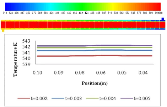
A. Material copper
Graph 3. Temperature variation across Outlet for varying Fin thickness Summary of CFD analysis resultsI
B. Mass flow rates 0.320kg/s
Sr no Thickness of
fin (m)
Temp. (k) Pressure
(Pascal)
Vel(m/s) Heat transfer
(W)
1 0.002 540.46 38 0.14 178074.16
2 0.003 541.39 37.8 0.14 178820.6
3 0.004 541.88 38 0.14 179189.36
[image:5.612.180.446.103.274.2]4 0.005 542.21 37.8 0.14 179464.3
Table 1. Variation of properties with different thickness copper
C. Mass flow rates 0.120kg/s
Sr no
Thickness of fin (m)
Temp. (k)
Pressure (Pascal)
Vel(m/s) Heat
transfer (W)
1 0.002 609.17 37.65 0.14 90208
2 0.003 609.47 38 0.14 90272
3 0.004 609.59 38 0.14 90304
[image:5.612.174.439.447.598.2]4 0.005 609.69 38 0.14 90320
Table 2. Variation of properties with different thickness copper.
VI.CONCLUSIONS
Based on the anaylsis the following important conclusions are conclude that
A. There is very minor changes occur in the pressure and velocity profile with increase of fin thickness as well as change of material that is pressure and velocity doesn’t get much affected by thickness of fin and material of fin
B. The temperature of the cold fluid at the outlet of the heat exchanger increases with increase the fin thickness.
VII. ACKNOWLEDGMENT
The authors thanks the Management and Principal of Mahatma Gandhi Institute of Technology , Hyderabad for encouraging and carry out this work
REFERENCES
[1] A.Behzadmehr, N. Galanis and A. Laneville, Low Reynolds number mixed convection in ertical tubes with uniform wall heat flux, International Journal of Heat and Mass Transfer 46 (2003), pp. 4823–4833.
[2] A. E. Bergles and W. J. Marner Augmentation of Highly Viscous Laminar Heat Transfer Inside Tubes with Constant Wall Temperature, Experimental Thermal and Fluid Science 1989; 2:252-267.
[3] A.E. Saad, A.E. Sayed, E.A. Mohamed, M.S. Mohamed, Experimental study of turbulent flow inside a circular tube with longitudinal interrupted fins in the streamwise direction, Experimental Thermal Fluid Science 15 (1) (1997) 1–15.
[4] Alam, P.S. Ghoshdastidar, A study of heat transfer effectiveness of circular tubes with internal longitudinal fins having tapered lateral profiles, International Journal of Heat and Mass Transfer 45 (6) (2002) 1371–1376.
[5] Bergles, A. E., and Joshi, S. D., Augmentation Techniques for Low Reynolds Number In-Tube Flow, in Low Reynolds Number Flow Heat Exchangers, S. Kakac, R. K. Shah, and A. E. Bergles, Eds. Hemisphere, Washington, D.C., pp. 695-720, 1983.
[6] B.Yu, J.H. Nie, Q.W. Wang, W.Q. Tao, Experimental study on the pressure drop and heat transfer characteristics of tubes with internal wave-like longitudinal fins, Heat Mass Transfer 35 (1999) 65–73.
[7] C.P.Kothandaraman.S.Subramanyan. Heat and Mass transfer Data book New age international publisher sixth edition.
[8] C.R. Friedrich, S.W. Kang, Micro heat exchangers fabricated by diamond machining, Precision Engineering 16 (1994) 56–59.