5
VIII
August 2017
Analysis of Stress and Strain with Variation in
Elastic Properties in Symmetric Laminated
Composite Rectangular Plate
Yogesh Pratap Singh1, Tikam Prasad2, Mukesh kumar3, Atul tiwari4, Aviral Sharma5
Department of Mechanical Engineering, National Institute of Technology, Raipur
Abstract: Composite materials play a key role in aerospace and many other fields .Normally we desire a very high strength to weight ratio, so it becomes vital to study composite properties with different elastic parameters along with different fiber direction & stacking arrangements. This paper contains all possible variations of stress and strain of different laminas of a laminated angle ply composite plate with elastic properties. The study of these variations can be used to optimize material properties of composites as per given application.
Keywords: Laminate, Lamina, CLPT, Cross Ply lamination, Angle ply lamination.
I. INTRODUCTION
Composite materials are materials constituted for two or more components, which remain independent at the macroscopic level when they become part of a structure. The main advantages for the use composite materials are high strength and high stiffness to weight ratio. These reasons put composites in service like Aerospace structures, Automobiles, Boats, Pipe lines, Buildings, Bridges etc.
A laminate is constructed by stacking a number of laminas in the thickness (z) direction. Each layer is thin and may have different fiber orientation. The fiber orientation, stacking arrangements and material properties influence the response from the laminate. For Cross Ply lamination consecutive fibers are in perpendicular directions while in Angle ply consecutive fibers are at some angle.
II. THEORY OF LAMINATED PLATES
The classical laminate plate theory (CLPT) is used to analyze the mechanical behavior of the composite laminated plates. We assume that plane stress condition is valid for each ply.
This theory is the extension of the classical plate theory. The plate response is influenced by the fiber direction, stacking arrangements, material properties. In this theory, for plate analysis the Kirchhoff's plate theory is assumed and contains the assumptions as follows. This theory deals the mechanics of composite laminated plates using stress strain relations.
A. Assumptions
Straight lines perpendicular to the mid surface before deformation is straight after deformation. The transverse normals do not experience elongation.
Transverse normal’s rotate such that they remain perpendicular to the mid surface after deformation.
B. Assumptions
The layers are perfectly bonded together.
The material of each layer is linearly elastic and has three planes of material symmetry. Each layer is of uniform thickness.
The strains and displacements are small.
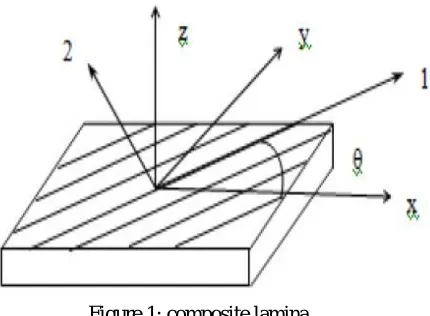
Figure 1:composite lamina
The above figure shows a composite lamina. The direction along the fiber axis is referred 1. The direction transverse to the fiber axis but in the plane of the lamina is refereed 2. The direction transverse to both the fiber axis and the plane of the lamina (out of page) is referred 3.
The 1-2 co-ordinate system can be considered to be local co-ordinates based on the fiber direction. However this system is in adequate as fibers can be placed at various angles with respect to each other and the structure. Therefore a new co-ordinate system needs to be defined that takes into account the angle the fiber makes with its surroundings. This new system is referred to as global co-ordinates (x-y system) and is related to the local coordinates (1-2 system) by the angle θ. A composite material is not isotropic
and therefore its stresses and strains cannot be related by the simple Hooke’s Law. This law has to be extended to two-dimensions and redefined for the local and global co-ordinate systems. The result is Equations (1) and (2).
Where σ1,2 are the normal stresses in directions 1 and 2; τ12 is the shear stress in the 1-2 plane; ε1,2 are the normal strains in directions
1 and 2; γ12 is the shear strain in the1-2 plane. [Q] is the reduced stiffness matrix; σx,y are the normal stresses in directions x and y; τxy
is the shear stress in the x-y plane; εx,y are the normal strains in directions x and y; γxy is the shear strain in the x-y plane; is the
transformed reduced stiffness matrix. The elements of the [Q] matrix in Equation (1) are dependent on the material constants and may be calculated using Equations (3).
Where E1,2 are Young’s modulus in directions 1 and 2; G12 is the shear modulus in the 1-2 plane; ν12,21 are Poisson’s ratios in the 1-2
and 2-1 planes The matrix in Equation (2) may be determined by Equation (4).
A, B and D matrices are known as extensional, coupling and bending laminate stiffness
Here k is no of layer and Zk terms are through thicknesses. The orthotropic layers are oriented such that the complete laminate is
symmetric across the middle surface. Due to this symmetry, the [B] matrix that relates the bending-extension coupling is effectively zero, [B]ij=0. The Zk terms are defined from the middle surface of the laminate as shown in Figure 2
Figure 2
C. Effective Elastic properties of laminates
It is important to calculate the Effective elastic properties of a Laminate, those are the effective extensional modulus in the x
direction, the effective extensional modulus in the y direction, the effective Poisson’s ratios and the effective shear modulus in the x-y plane . These constants allow us to do classical mechanics of laminates like stress analx-ysis and buckling analx-ysis.
Here aij is elements of compliance matrix, h are the laminate thickness. In order to calculate the engineering properties of a
symmetric laminate using above equations one needs to calculate the extensional stiffness matrix [A] and then invert it to obtain the compliance matrix [a]
III. PROBLEM STATEMENT
Our aim is to study variation of stress-strain with Elastic properties induced at various laminas of a Symmetrical Angle ply Rectangular Composite laminate in ANSYS.
IV. ANALYSIS CONDITIONS
We have used ACP MODULE in ANSYS 18 for our analysis. Followings are the details of Analysis conditions:
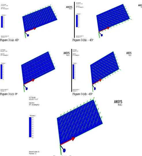
A. Plate of Dimension 150 ×80 mm, fixed at 80mm end.
B. (45°,-45°,-0°,-45°,45°) symmetrical layup for the plate each being 0.3 mm thick as shown in figure 3(a-e)
Figure 3 (a): 45o Figure 3 (b): - 45o
Figure 3 (c): 0o Figure 3 (d): -45o
[image:5.612.41.534.186.725.2]C. Material applied is Epoxy Carbon UD with properties shown in figure 4
Figure 4: Epoxy Carbon UD
D. Small transverse load of 100 N is applied over top of the plate.
V. RESULTS & CONCLUSIONS
A. Stress
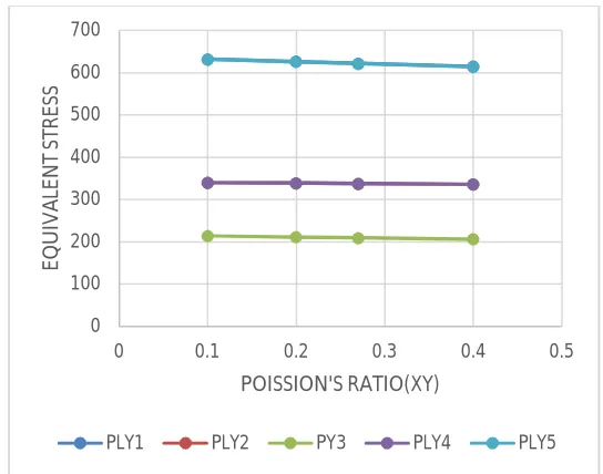
1) Variation of stress with variation in Poisson’s ratio is shown in figure 5(a-c)
2) With increase in value of Poisson’s ratio in xy (plane of fibers), stress decreases and stress is symmetrically distributed across the middle lamina.(e.g. stress value for lamina 1& 5 and 2 & 4 are same due to symmetry)
3) With change in value of Poisson’s ratio in yz or zx plane, stress remains same for a particular lamina and stress is
symmetrically distributed across the middle lamina.(e.g. stress value for lamina 1& 5 and 2 & 4 are same due to symmetry).
4) Stress is least for middle lamina and maximum for outer laminas.
Figure 5(a)
0 100 200 300 400 500 600 700
0 0.1 0.2 0.3 0.4 0.5
EQ
UI
V
A
LE
N
T
ST
R
ES
S
POISSION'S RATIO(XY)
[image:6.612.187.459.506.720.2]Figure 5(b) Figure 5(c)
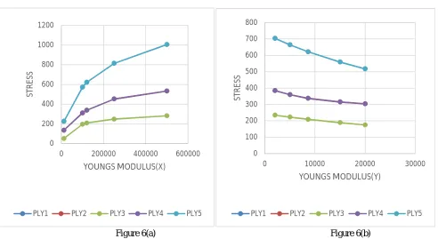
5) Variation of stress with variation in Young’s Modulus is shown in figure 6(a-c)
Figure 6(a) Figure 6(b)
a) With increase in value of Young’s Modulus in y direction, stress decreases and stress is symmetrically distributed across the middle lamina.(e.g. stress value for lamina 1& 5 and 2 & 4 are same due to symmetry)
b) With increase in value of Young’s Modulus in x direction, stress increases and stress is symmetrically distributed across the middle lamina.(e.g. stress value for lamina 1& 5 and 2 & 4 are same due to symmetry)
c) With change in value of Young’s Modulus in z direction, stress remains same for particular lamina and stress is symmetrically distributed across the middle lamina (e.g. stress value for lamina 1& 5 and 2 & 4 are same due to symmetry).
d) Stress is least for middle lamina and maximum for outer laminas.
0 100 200 300 400 500 600 700
0 0.1 0.2 0.3 0.4 0.5
EQ UI V A LE N T ST R ES S POISSION'S RATIO(YZ)
PLY1 PLY2 PY3 PLY4 PLY5
0 100 200 300 400 500 600 700
0 0.1 0.2 0.3 0.4 0.5
EQ UI V A LE N T ST R ES S POISSION'S RATIO(ZX)
PLY1 PLY2 PY3 PLY4 PLY5
0 200 400 600 800 1000 1200
0 200000 400000 600000
ST
R
E
SS
YOUNGS MODULUS(X)
PLY1 PLY2 PLY3 PLY4 PLY5
0 100 200 300 400 500 600 700 800
0 10000 20000 30000
ST
R
ES
S
YOUNGS MODULUS(Y)
[image:7.612.44.536.342.611.2]Figure 6(c)
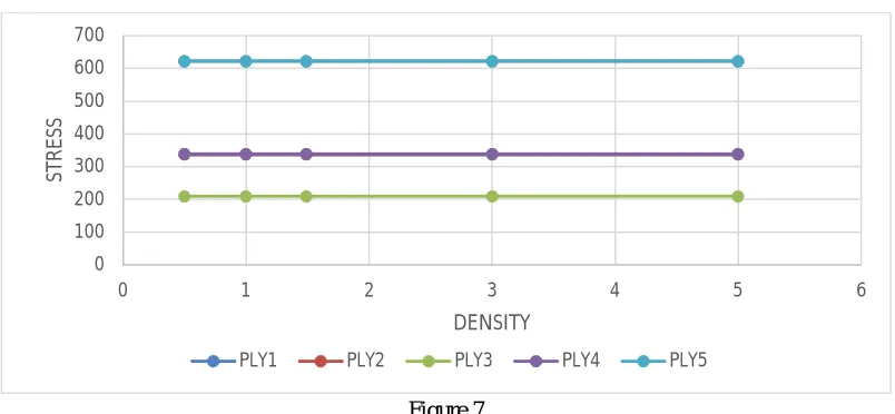
[image:8.612.122.492.76.262.2]6) Variation of stress with variation in Density is shown in figure 7
Figure 7
7) With change in value of Density of Material, stress remains same for particular lamina and stress is symmetrically distributed across the middle lamina (e.g. stress value for lamina 1& 5 and 2 & 4 are same due to symmetry).
8) Stress is least for middle lamina and maximum for outer laminas.
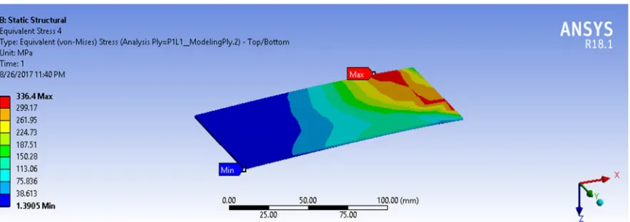
Figure 8(a-c) shows stress Analysis in ANSYS for Poisson’s Ratio=0.4
Figure 8(a): stress for lamina 1 & 5
0 100 200 300 400 500 600 700
0 5000 10000 15000 20000 25000
ST
R
ES
S
YOUNGS MODULUS(Z)
PLY1 PLY2 PLY3 PLY4 PLY5
0 100 200 300 400 500 600 700
0 1 2 3 4 5 6
ST
R
E
SS
DENSITY
[image:8.612.106.508.298.484.2] [image:8.612.79.535.565.709.2]Figure 8(b): stress for lamina 2 & 4
Figure 8(c): stress for lamina 3(middle)
B. STRAIN :
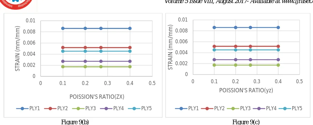
1) Variation of strains with variation in Poisson’s ratio is shown in figure 9(a-c)
Figure 9(a)
0 0.001 0.002 0.003 0.004 0.005 0.006 0.007 0.008 0.009 0.01
0 0.1 0.2 0.3 0.4 0.5
ST
R
A
IN
(
m
m
/m
m
)
POISSION'S RATIO(XY)
[image:9.612.90.532.74.230.2]Figure 9(b) Figure 9(c)
2) Variation of strain with variation in Poisson’s ratio is shown in figure 9(a-c)
a) With increase in value of Poisson’s ratio in xy (plane of fibers), strain decreases for lamina 1, 2& 3, and increases for lamina 4 and 5 since 1&2 and 4&5 are in opposite side of middle lamina.
b) With change in value of Poisson’s ratio in yz or zx plane, strain remains same for a particular lamina.
c) Strain is least for middle lamina and maximum for first lamina.
3) Variation of strains with variation in Young’s modulus is shown in figure 10(a-c)
Figure 10(a)
Figure 10(b) Figure 10(c)
0 0.002 0.004 0.006 0.008 0.01
0 0.1 0.2 0.3 0.4 0.5
ST R A IN ( m m /m m ) POISSION'S RATIO(ZX)
PLY1 PLY2 PLY3 PLY4 PLY5
0 0.002 0.004 0.006 0.008 0.01
0 0.1 0.2 0.3 0.4 0.5
ST R A IN ( m m /m m ) POISSION'S RATIO(yz)
PLY1 PLY2 PLY3 PLY4 PLY5
0 0.005 0.01 0.015 0.02 0.025
0 100000 200000 300000 400000 500000 600000
ST
R
A
IN
YOUNGS MODULUS(X)
PLY1 PLY2 PLY3 PLY4 PLY5
0 0.002 0.004 0.006 0.008 0.01 0.012
0 10000 20000 30000
ST
R
A
IN
YOUNGS MODULUS(Y)
PLY1 PLY2 PLY3 PLY4 PLY5
0 0.002 0.004 0.006 0.008 0.01
0 10000 20000 30000
ST
R
A
IN
YOUNGS MODULUS(z)
PLY1 PLY2 PLY3
[image:10.612.38.551.55.260.2] [image:10.612.68.533.355.716.2]a) With increase in value of Young’s Modulus in y and x direction, strain decreases.
b) With change in value of Young’s Modulus in z direction, strain remains same for particular lamina.
c) Strain is least for middle lamina and maximum for first lamina.
4) Variation of strains with variation in Density is shown in figure 11
a) With change in value of Density of Material, strain remains same for particular lamina.
b) Strain is least for middle lamina and maximum for first lamina.
Figure 11
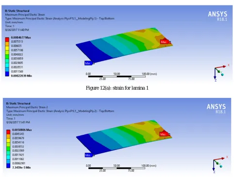
Figure 12(a-e) shows strain Analysis in ANSYS for Poisson’s Ratio=0.4
Figure 12(a): strain for lamina 1
Figure 12(b): strain for lamina 2
0 0.002 0.004 0.006 0.008 0.01
0 1 2 3 4 5 6
ST
R
A
IN
DENSITY
[image:11.612.45.560.131.331.2] [image:11.612.65.547.360.725.2] [image:11.612.71.548.364.532.2]Figure 12(c): strain for lamina 3
Figure 12(d): strain for lamina 4
Figure 12(e): strain for lamina 5
VI. FURTHER WORKS THAT CAN BE DONE
Other than what analysis we have done, we can also work on following:
A. Variation of stress and strains in different lamina with changing thermal Conditions.
[image:12.612.44.569.46.628.2]REFERENCES
[1] JN Reddy “Mechanics of Laminated Composite Plates and Shells”
[2] The basic mechanics of of composite materials are from “Mechanics of Composite materials by Robert M.Jones” [3] Engineering mechanics of composite materials by Isaac M.Daniel Ori ishai
[4] K. Pradeep Chand, K. Chaitanya, “Study the Effects of Free Vibration and Effective Elastic Properties with Variation of Layer Orientation of Symmetric Laminate Plates”, ijsr ,Volume 5 Issue 5, May 2016, Paper ID: NOV163792