HEWLETT~PACKARD
COMPUTER MAINTENANCE COURSE
HEWLETT- PACKARD
COMPUTER MAINTENANCE COURSE
VOLUME
XIX
STUDENTS MANUAL
HP TIME SHARE MULTI- PROCESSOR
ENVIRONMENT
(HP STOCK NO. 5951-1400)
-NOTICE-The information contained in this manual is for training purposes only. Consult the Hewlett·Packard documentation supplied with the computer for current information con-cerning the specific computer system furnished.
The information contained in this publication may not be re-produced in any form without the expressed consent of the Hewlett-Packard Company.
COPYRIGHT HEWLETT-PACKARD COMPANY 1971
ii
FOREWORD
The Hewlett Packard family of Time Share Systems includes the 2000A, 2000B and 200OC. The previous manual in this series covered the HP 2000A Time Share System (stock number 5951-1346). It dealt with the philosophy of the Time Share system. Its emphasis was intensively hardware oriented. It dealt particularly with the Scheduler, Multiplexor, and operating environment.
This present volume deals with the multi-processor environment used with the 2000B and 2000C. The addition of the second processor allows a substantial increase in the number of users along with other system improvements.
The purpose of this manual is to describe the operating environment, especially the inter-processor communications and power fail considerations. It gives specific information on the tables and pointers for the 2000B.
There are further changes in the 200OC. These include the drivers and tables required to implement the Moving Head Disc capability. The loading and sleeping technique required significant changes (between 2000B and 200OC). The com-munications between the system processor and the Comcom-munications Processor program is virtually identical. It is hoped that this manual will be helpful for both 2000B and 2000C systems.
CONTENTS
PAGE
Chapter 1 MULTI-PROCESSOR TIME SHARE 1-1
1-1 Multi-processor Environment 1-1
1-2 2000B Time Share System 1-2
Chapter 2 COMMUNICATIONS PROCESSOR FUNCTIONS 2-1
2-1 Multiplexor Hardware 2-1
2-2 Multiplexor Software 2-2
2-3 Communications Processor TTY Tables 2~6
2-4 Teletype Buffer Pointers 2-8
2-5 Base Page Locations Communications Processor 2-11
2-6
Core Map Communications Processor 2-122-7 Phones Routine 2-12
Chapter 3 PROCESSOR COMMUNICATIONS 3-1
3-1 Processor Interconnect Kit 3-1
3-2 Communications (System to Communications
Processor) 3-2
3-3 Code Format 3-2
3-4 Command Initiation 3-5
3-5 Command Definitions System Processor to
Communications Processor 3-11
3-6 Communications Processor to System Processor
Command Initiation 3-27
3-7 Command Definitions Communications Processor
to System Processor 3-27
Chapter 4 SYSTEM PROCESSOR FUNCTIONS
(2000B SYSTEM) 4-1
4-1 Hardware Configuration (2000B) 4-1
4-2 Base Page .constants 4-7
4-3 TTY Tables (System Processor) 4-7
4-4 Loader 4-15
Chapter 5 SYSTEM POWER FAIL 5-1
5-1 AC Power Considerations 5-1
5-2 Communications Processor Power Down 5-1
5-3 Communications Processor Power Up 5-2
5-4 System Processor Power Failure 5-2
5-5 System Processor Restart 5-7
5-6 Power Fail Symptoms 5-9
ILLUSTRATIONS
FIGURE TITLE PAGE
1 2000B Time Share System 1-3
2 Multiplexor Data and Phones 2-3
3 Multiplexor Routine Block Diagram 2-4
4 Input/Output Buffering 2-10
5 Core Map 2-13
6 Phones Block Diagram Sheet 1 2-15
Sheet 2 2-16
7 Inter-Processor Communications Block Diagram 3-3
8 Simplified Processor Interconnect Logic Diagram 3-4
9 Command Code Format 3-5
10 Command Initiation (System Processor to
Communication Processor) 3-9
11 OCR Output a Character 3-17
12 STE Start ENTER Timing 3-18
13 GTC Get Next Character 3-18
14 PHO Phones Timing 3-18
15 BKS Backspace Buffer Pointer 3-19
16 SBP Save Buffer Pointer 3-19
17
RBP Restore Buffer Pointer 3-1918 INI Initiate System 3-20
19 UIR User is Running 3-21
20 UNR User Not Running 3-21
21 IWT Input Wait 3-21
22 HUU Hang User Up 3-21
23 ULO User Logged On 3-21
24 ECO Echo On 3-22
25 ECF Echo Off 3-22
26 TPO Tape Mode On 3-22
27 ILl Any Illegal Input 3-22
28 NUC New User Called 3-23
29
KAO Kill all Output 3-2330 ALI Allow Input 3-23
31 OWT Output Wait 3-23
32 FAS Fast Terminal 3-24
33 SLO Slow Terminal 3-24
34 IBF Is Buffer Full 3-24
35 IPF Is Port Fast 3-25
36 Communication Processor Requests to System
Processor 3-25
37 HVL Have a Line 3-31
38 ABR User Aborted 3-31
FIGURE 39 40 41 42 43 44 45 46 TABLE 1 2 3 4 5 6 7 8 9 10 11 12
ILLUSTRATIONS (Cont'd)
TITLE
BFL Buffer is Full
BFE Buffer (almost) Empty
ETO ENTER Timed Out
UHU User Hung Up
2000B Board Locations (2116B) 2000B Board Locations (2116C)
Communications Processor Power Fail Block Diagram System Processor Power Fail Block Diagram
Sheet 1 Sheet 2
TABLES
TITLE
Communications Processor TTY Table
System Processor to Communications Processor Requests
Communications Processor to System Processor Requests
2000B Minimum Hardware Configuration 2000B Optional Hardware
Disc/Drum Reference Table
Logical to Physical Track Conversion Logical to Physical Sector Conversion Equipment Table (2000B) Sheet 1
Sheet 2 Important Core Locations
Contents of LIB
System Processor TTY Table
SECTION INDEX
Multi-Processor Time Share
Communications Processor Functions
Processor Communications
System Processor Functions
CHAPTER 1
MULTI-PROCESSOR TIMESHARE
1-1 Multi-Processor Environment
The advantages of dividing the system activities between two processors will be more apparent with a clear understanding of the 2000A system. This training manual relies heavily on the basic system philosophy contained in the HP 2000A Time Share System manual (stock number 5951-1346). References will be made from time-to-time to that volume in the format: HP 2000A TSS Figure
#
Page#
Before proceeding please review the following HP 2000A TSS sections:
1-4 Time Sharing, 1-7 Response Time, 3-1 Multiplexor, 3-2 Multiplexor Software, and Chapter 4 Multiplexor System.
Let us consider the 2000A system from the standpoint of its limitations or weak-nesses. The incremental cost of a.dding more ports (i.e. more than 16) is low from the cost of the hardware required. However, due to core limitations (in the present configuration) it is impossible to exceed the 16 port limit. It would require additional memory space for TTY buffers and TTY tables which is unavail-able. Also important is the fundamental change required in status words and flags. The 16 bit machine placed an effective limit at 16 ports without restructuring.
The output buffer was limited to 50 words. Whenever the 100 character output storage was exceeded the Basic Interpreter would initiate an output suspend. This requires a wasted core to drum swap followed by a drum to core swap. Although in the 2000A this limitation was not critical, as one increases the number of ports the wasted time becomes increasingly important. An increase in buffer size would be desirable as the number of ports is increased. The time spent servicing the routine Multiplexor interrupts was significant whenever the number of active ports was high or the quantity of input/output traffic was high.
Finally, although certain desirable user and system features were possible the core limitation absolutely prevented their consideration. The use of a second computer makes possible effective solutions to the system limitations listed above.
It also allows the addition of rather important new features.
Two problems arise as a result of the multi-processor environment. One is the power failure techniques and procedures. Another is the communications required to gain access to data available only in the other processor and the initiation of action by the other processor. We will consider these in detail in Sections 3-2 and 3-6.
1-2 20008 Time Share System
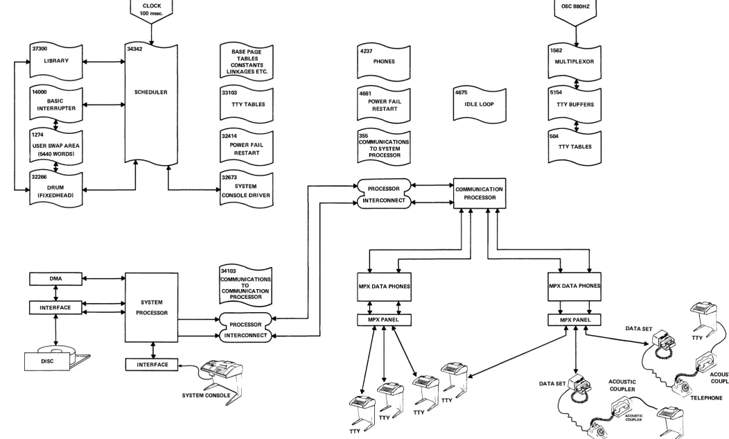
Compare Figure 1 2000B Time Share System with the HP 2000A TSS Figure 4 (2000A Time Share System), page 3-3. The comparison will show that the same basic functions exist. They are now merely distributed between the two processors. If the System Processor and Communications Processor computers along with the processor interconnect kits and the communication modules were drawn within a system "black box" these two drawings would be virtually identical.
F or the 2000C the main addition to this diagram would be the Moving Head Disc hardware and drivers associated with the System Processor.
The system improvements are now easy to visualize. The 8K memory (in the communications Processor) allows a very substantial increase in TTY buffer size. Each port now has 150 words. This is helpful particularly in output mode in reducing the swapping for output suspensions, and for input while in tape mode. Simultaneous tape input from a large number of ports places a stringent require-ment on buffer size. It is satisfied by the 300 character buffer. A glance at the core map (figure 5) indicates the substantial core dedication to these buffers.
In the 2000A a clear functional division existed between the multiplexor and scheduler. The multiplexor indicated a port was ready for service by setting the respective bit in MPCOM. Now this is done through the processor communica-tions by setting a status bit in the System Processor TTY tables. The finished line (in the buffer) was immediately available to the Scheduler or Basic
Interpreter. Now the characters are passed as a result of a character request or character output command. A clearer understanding of the TTY tables will result as we see how they were split between the processors with additions and duplications. This manual is based on the listings for the 2000B Revision B. The stock numbers are:
2000B TSB System (Rev B)
2000B TSB Loader (Rev B)
24239-60001 Part One 24239-60002 Part Two
24238-60001.
2000B/C TSB Communications Processor (Rev A) 24231-60001
37300
LIBRARY
14000 BASIC INTERRUPTER
1274
USER SWAP AREA (5440 WORDS)
32266
34320 CLOCK
34342
SCHEDULER
SYSTEM
PROCESSOR
BASE PAGE TABLES CONSTANTS LINKAGES ETC.
33103
TTY TABLES
32414
POWER FAIL RESTART
32673 SYSTEM CONSOLE DRIVER
34103
COMMUNICATIONS TO COMMUNICATION
PROCESSOR
PROCESSOR
4237
PHONES
4675
IDLE LOOP
355
COMMUNICATIONS TO SYSTEM PROCESSOR
PROCESSOR COMMUNICATION
INTERCONNECT PROCESSOR
MPX DATA PHONES
OSC 880HZ
MULTIPLEXOR
TTY BUFFERS
MPX OAT A PHON ES
ACOUSTIC COUPLER
w:
~iIbam~'· ACOUSTIC ::;.-:;; COUPLER
,,;j ~\
/TELEPHONE
FIGURE 1. 20008 TIME SHARE SYSTEM
[image:11.1226.110.1162.79.711.2]CHAPTER 2
COMMUNICATIONS PROCESSOR FUNCTIONS
The use of the second processor to service the Multiplexor requires certain pointers, tables and software routines. This chapter will consider these require-ments. It would be desirable to review chapters 5 and 6 from the HP 2000A TSS Manual.
2-1 Multiplexor Hardware
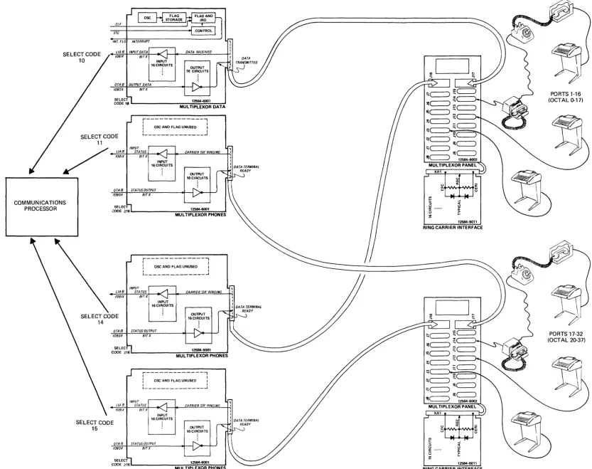
The Communications Processor provides greatly expanded multiplexor capability. Figure 2 shows the multiplexor data and phone arrangement. Compare with HP 2000A TSS Figure 5 on Page 4-3.
The maximum user capability allows 32 users. These may be hard wired (direct cable) or coupled through data phones.
The minimum system consists of a data board in Select Code 10. This allows up to 16 direct users. If the Data board in Select Code 11 is unnecessary a Priority Jumper must be substituted. Since the processor communications operates under Interrupt, the priority string must be intact.
As the system is expanded to include Phones the Ring Carrier Interface and Phones board must be installed. Notice the relationship between the Data and Phones board. The Phones board in select code 14 is required for users 0 to 15 in conjunction with the data board in select code 10. The Phones board in select code 15 is required for users 16 to 31 in conjunction with the data board in select code 11. Any compatible installation is possible between the minimum or maximum configuration.
Notice that only the first Data board interrupt circuitry is utilized. This one interrupt controls the servicing of all Data and Phones.
A change in the PHOnes command was implemented. The select code is no longer specified. The only parameter required is the log on time limit. Thus PHO-14,180 would be misinterpreted, and would result in a log on time of 14 seconds. An additional change precludes the use of PHO-0 to turn off the phones. The two possibilities now allow PHO-1 which would ring then disconnect in one second, or manual intervention to turn off the data phone set.
2-2 Multiplexor Software
The 2000A was an example of extremely tight and efficient coding. Core was so valuable that virtually every trade off was resolved with the solution requiring less core. Now with a separate computer dedicated to the user processing and communication tasks, core is more abundant. The trade offs between speed or efficiency vs coreTequirements can now be resolved at the expense of program size.
If we consider the implications of 32 users we see the availability of 32 bits by using 2 computer words. Now our flag words require 2 addresses. Glance ahead at the locations described in section 2-5. These describe 6 flag functions requiring 12 memory addresses. Review the definitions.
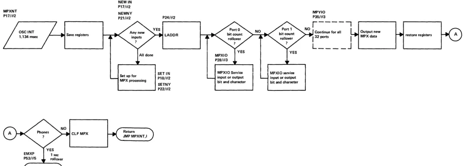
Figure 3 shows the greatly simplified block diagram for the multiplexor routine. The multiplexor routine operates under the in.terrupt mode. The oscillator on the data board in select code 10 interrupts every 1.134 millisecond. Since this has the highest I/O priority it will override the processor communications if flag (/) is enabled. The multiplexor then ascertains whether any new user input requires servicing. These are set up one at a time. Then the LADDR routine determines whether bit processing is required by any active user. Any such requirement is handled by the MPXIO routine.
The phones routine is entered ten times each second. This is determined by counting 88 multiplexor interrupts.
The multiplexor flag holds off the interrupt from lower priority devices. It also holds a subsequent multiplexor oscillator interrupt in the "storage FF". Thus it will not be lost due to an unusually large amount of multiplexor business during any specific interrupt. The multiplexor flag is cleared as the routine is exited.
It will now be beneficial to review the HP 2000A TSS Chapter 4 Multiplexor System. The Communications Processor Multiplexor technique is quite similar. The apparent differences include the method of signalling user business to the scheduler and the implications of the FAST port command.
For FAST port command a count of -2 is placed in the BTI~.1 table entry instead of the -4 for normal 10 cps terminals. This is shown on HP 2000A TSS
Figure 6 on page 4-7 near the right margin. This occurs as the ISZ entry is placed
CLF
STC
tNT FLG INTERRUPT
SELECT CODE 10
LlAIB INPUT DATA IOBIX Blrx
DATA RECEIVED
INPUT
COMMUNICATIONS PROCESSOR
OTAIB OUTPUT DATA IOBOX BIT X
16 CIRCUITS
OUTPUT 16 CIRCUITS
r---,
I I
i OSC AND FLAG UNUSED I
I I
SELECT CODE 11
~---....I
INPUT LlAiB STATUS IDBIX BtTX
INPUT 16 CIRCUITS
orA/8 STA TUS OUTPUT
CARRIER 'OR'RINGING
OUTPUT 16 CIRCUITS
IOBOX BIT X
~~~E~~6~ ____________ ~~~~1~~~~~~1~~~ MULTIPLEXOR PHONES
r---,
I I
: osc AND FLAG UNUSED I
I I
~---....I
INPUT
LlAiB STA TUS CARRIER 'OR' RINGING IOBIX BIT X
INPUT 16 CIRCUITS
orA/8 srA TUS OUTPUT
OUTPUT 16 CIRCUITS
1080X BIT X
C~~E~~6~ ________________ ~~1~~~~~~1~~~ MUL TIPLEXOR PHONES
SELECT CODE
15
LlA 'B IOBIX
r---,
I I
: OSC AND FLAG UNUSED I
I I
L _ _ _ _ _ _ _ _ _ _ _ _ _ _ ....I
INPUT STATUS
BITX
INPUT 16 CIRCUITS
CARRIER 'OR' RINGING
OUTPUT 16 CIRCUITS
OTAI8 STA TUS OUTPUT IOBOX BIT X
C~~~E~~6~ ____________ ~~~~1~~~~~1~~~
MULTIPLEXOR PHONES
12584-6011
RING CARRIER INTERFACE
XA1
~ ft a: ffi c.J c.J
'"
I- .J
::; <t
c.J c.J a: ii:
13
>-~
I-12584-6011
RING CARRIER INTERFACE
PORTS 1·16 (OCTAL 0-17)
PORTS 17·32 (OCT AL 20-37)
FIGURE 2. MULTIPLEXOR DATA AND PHONES
[image:15.1229.346.1180.64.723.2]MPXNT
P17/#2
OSCINT
1.134 msec /---11" Save registers
NEWIN
P17/#2
NEWNV
P21/#2
Set up for MPX processing
P24/#2
LADDR
SETIN
P18/#2
SETNV
"-_ _ _ _ _ -' P22/#2
CLF MPX Return JMPMPXNT,I
FIGURE 3. MULTIPLEXOR ROUTINE BLOCK DIAGRAM
MPXIO P28/#3
MPXIO Service input or output bit and character
MPXIO service input or output bit and character
MPVIO
P35/#3
Continue for all 132 ports 1
L ____
J
Output new
[image:16.1233.44.981.359.695.2]When a full in ut line is available, or the output buffer is reduced to 10 characters., _ .... ...,,'" _ , ., f • . " . , ' - -~ ,
-The feature of allowing the console operator to specify the number of ports means that certain unused hardware ports are not provided with a swap track. To insure against inadvertant noise glitches or operator hardware error that would prove unhealthy to the system the IG and IG 1 flags are provided. The System Processor sets these bits upon awake from sleep and during initial system con-figuration. These bits instruct the multiplexor to ignore the user even though an apparant space might be received.
The incoming multiplexor data is masked by the IG bits and becomes the INBIT data. This is further checked against the INPTF words which indicate the users which are currently being serviced by the multiplexor routine. The residue are those new inputs requiring new set up.
The FAST command clears the corresponding bits in the F AF flag word (for 220 baud rate). This data is used during set up to determine the number of interrupts to the middle of the start bit. During bit count rollover in the MPXIO routine it is used again to determine the number of interrupts to the middle of the next bit.
IOTOG is used within the MPXIO to determine whether an input or output character is being processed.
The ABTST flag indicates the users who are being checked for an abort. The abort allows terminating an operation such as RUN or LIST by the Basic Interpreter. There are certain functions that cannot be allowed t() terminate
IJrematurely.
~'fhese 'lncf~dethep;~ce~~-
of compilinK';~'~~mi-~o~pili~g:'r~~numbering,
or-;:p·£enc1ltl.i-A"j;·Y~~rthese w~dl~~;-'~
the
inter~~l'program ~epresent~tio~ in . '.disarray. A user in potential abort must be checked each interrupt for a data change, whereas an active user is only processed on bit count rollover.
2-3 Communications Processor TTY Tables
The functions of the Teletype table entries can be organized by their relationship to Multiplexor, Scheduler, Basic Interpreter, or general system information. In the 2000A they were all located together in a common TTY table. Now for the 2000B and 2000C we see a splitting by functions and only the necessary TTY table entries are provided in each processor.
The entries which were retained in the System Processor Coding but are not required in the Communication Processor Coding, include the swap area related . entries, the scheduler queue related entries, and some general entries. The swap
area entries are: DISC and PROG. The scheduler entries are: LINK, PLEV, RSTR, and CLOC. The general entries are ID, NAME, and TIME. These are all discussed in Section 4-3.
Three new entries are used in the Communications Processor. The ATIM and TIMO are required by the Enter command. The third one BSA V replaced an entry in the users swap area (BADDR), and provides reset capability. The Basic Interpreter has certain branch conditions in evaluating the syntax line. The buffer pointer BHED is advanced through the character sequence in the line. BSAV now is required in the
Communications Processor to allow resetting to the beginning of the current line (or to the beginning of the branch condition).
One duplication exists in the TTY Tables for both the System Processor and Communication Processor. This is the STAT entry. You will notice a great deal of difference between these two entries. The status of the user has different implications for the multiplexor in the Communications Processor than for the scheduler or Basic Interpreter in the System Processor. The description of the status bits in the TTY definitions will help to clarify the manner in which these status entries are used.
The following list of TTY Table entry definitions is arranged in the sequence in which they appear within the TrY table.
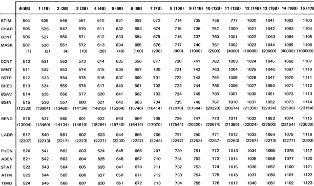
The Teletype tables in the Communications Processor consist of 17 entries for each of the 32 possible users. F our en tries are fixed depending only on the users port number (MASK, BGIN, BEND, & LADR).
BTIM Is a counter location which counts the multiplexor interrupts correspond-ing to the individual bits. It is incremented by the ISZ instruction in the LADDR coding. BTIM rollover indicates required servicing by the MPXIO routine for bit processing.
BCNT
MASK
Counts the number of bits within a character for both input and output mode.
A "one" in the bit corresponding to the port number allows AND and XOR type instructions to update pointers. The value is a constant for each port number.
The next five entries are associated with the character buffer for input and output manipulation. Refer Section 2-4.
CCNT* Contains the number of characters to be output including the current one. The value is in minus form.
BPNT* Points to the location in which the next input character will be placed. In output it points to the character currently being transmitted.
BSTR * Points to the first character of the current line.
BHED* Points to the head of the input or output character sequence.
BSAV* Points to the beginning of the current line in the buffer, or sometimes to an intermediate branching point, and allows BHED to be reset if necessary.
The next three entries are pointer addresses depending on the user port number.
BGIN* Associated with each port is a 150 word buffer. BGIN contains the address of the first word.
BEND* BEND is the address of the next word following the end of the physical buffer.
LADR The multiplexor contains a ladder subprogram. LADR is the address of an instruction corresponding to the user port. This allows this instruction to be changed from a JMP to an ISZ during character processing. The ISZ performs the bit timing. It is replaced by a JMP when the character is complete.
Two entries are used for general timing.
PHON
ABCN
Is used for timing required by the Phones Logic, including log on and disconnect timing. The location is a timeout counter when in use.
This is a counter used by the multiplexor to handle possible abort timing. Break key must be depressed for 114 msec to achieve abort. When abort timing is taking place user data is compared every interrupt.
*Refer to Section 2-4 for address convention.
STAT This contains the status of the user. The System Processor also has a stat entry but the codes are different.
TPBT bit
0
User in tape modeSTBT bit 1 Stop bit due to full output buffer . ESBT bit 2 Escape was hit, or input buffer full
in tape mode NIBT bit 3 No input allowed LDBT bit 4 Line dropout occurred LTBT bit 5 Log on timing
ENBT bit 6 Enter timing HUBTbit 7 Hang user up RNBTbit 8 User is running
The next two entries are new with the 2000B and provide timing capability for the ENTER statement.
ATIM
TIMO
Contains allowed time for ENTER statement execution. Time value in tenths of a second. Initiated by System Processor STE. Time limit value in seconds is converted to tenths before storing in ATIM.
Loaded with the 2's complement value of ATIM. Following the output message for the ENTER statement this value is incremented once per phone servicing. The process is terminated either by an input
carriage return or by TIMO rollover. The response time in seconds is determined by adding ATIM to TIMO and dividing by 10.
Table 1 lists the memory addresses for each of the Communications Processor TrY table entries. Notice that the contents of those entries with fixed data is shown. Only the first 16 ports are included. The pattern is evident. It is expected that the reader will have a Listing and could easily generate specific table entries for a user with port number 20 to 37.
2-4 Teletype Buffer Pointers
0(0B) 1 (1B) 2 (2B) 3 (3B) 4 (48)
BTIM 504 525 546 567 610
CHAR 505 526 547 570 611
BCNT 506 527 550 571 612
MASK 507 530 551 572 613
(1) (2) (4) (10) (20)
CCNT 510 531 552 573 614
BPNT 511 532 553 574 615
BSTR 512 533 554 575 616
BHED 513 534 555 576 617
BSAV 514 535 556 577 620
BGIN 515 536 557 600 621 (12330) (13004) (13460) (14134) (14610)
BEND 516 537 560 601 622 (13004) (13460) (14134) (14610) (15264)
LADR 517 540 561 602 623
(2207) (2213) (2217) (2223) (2227)
PHON 520 541 562 603 624
ABCN 521 542 563 604 625
STAT 522 543 564 605 626
ATIM 523 544 565 606 627
TIMO 524 545 566 607 630
24231-60001 (Rev A)
N I
\D
TABLE 1
COMMUNICATIONS PROCESSOR TTY TABLE
5 (58) 6 (6B) 7 (78) 8 (10B) 9 (11B) 10 (12B)
631 652 673 714 735 756
632 653 674 715 736 757
633 654 675 716 737 760
634 655 676 717 740 761
(40) (100) (200) (400) (1000) (2000)
635 656 677 720 741 762
636 657 700 721 742 763
637 660 701 722 743 764
640 661 702 723 744 765
641 662 703 724 745 766
642 663 704 725 746 767
(15264) (15740) (16414) (17070) (17544) (20220)
643 664 705 726 747 770
(15740) (16414) (17070) (17544) (20220) (20674)
644 665 706 727 750 771
(2233) (2237) (2243) (2247) (2253) (2257)
645 666 707 730 751 772
646 667 710 731 752 773
647 670 711 732 753 774
650 671 712 733 754 775
651 672 713 734 755 776
11 (138) 12 (148) 13 (15B) 14 (16B) 15 (17B)
777 1020 1041 1062 1103
1000 1021 1042 1063 1104
1001 1022 1043 1064 1105
1002 1023 1044 1065 1106
(4000) (10000) (20000) (40000) (100000)
1003 1024 1045 1066 1107
1004 1025 1046 1067 1110
1005 1026 1047 1070 1111
1006 1027 1050 1071 1112
1007 1030 1051 1072 1113
1010 1031 1052 1073 1114
(20674) (21350) (22024) (22500) (23154)
1011 1032 1053 1074 1115
(21350) (22024) (22500) (23154) (23630)
1012 1033 1054 1075 1116
(2263) (2267) (2273) (2277) (2303)
1013 1034 1055 1076 1117
1014 1035 1056 1077 1120
1015 1036 1057 1100 1121
1016 1037 1060 1101 1122
[image:21.802.75.689.124.488.2]BGIN
BSTR=BHED=BSAV _ f
~
BGIN
LINE 9 LINE 10
BHED BGIN
~/"> /",0,.'," i·'.~.1
/",.y...b A/,?;/I,>\II ,l//' .::'
/,i
,,;y. ~;.',;' .$ >t:J P.'i1"~;
FIGURE 4. INPUT/OUTPUT BUFFERING
\
\\
BSTR
I
BEND
~
BEND
~~~++++++++~~UU+fo~PUTJ
~
CCNT = -# OF CHARACTERS
IN THE BUFFER
,"lJO.lNT.:s 70 .' ," \1'
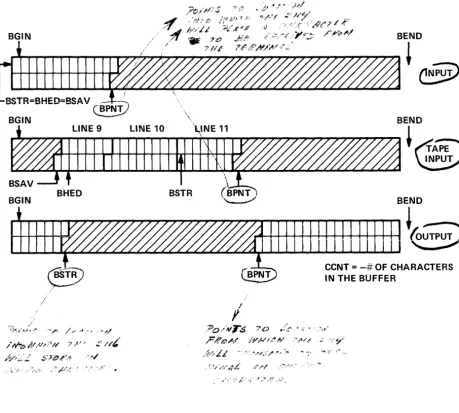
[image:22.621.63.523.172.585.2]Figure 4 shows the use of buffer pointers. BGIN always points to the first character position in the buffer. It allows easy resetting of other buffer pointers. BEND points to the first character beyond the users buffer. It is used primarily to test for wrap around in TAPE mode or OUTPUT. In normal input all
characters in excess of the full buffer length are lost.
For input BSTR
=
BHED=
BSAV and all are equal to the physical beginning of the buffer. BPNT oints to the next se uential osition into which a character may be placed. At teen 0 t e input line the system processes the line. Ittl'iefi outputs a carriage return. The end of the output resets the buffer pointers.
For output the buffer is merely a sequential buffer for up to 300 ASCII charac-ters. Lines have no significance. BSTR points to the next available location for an output character. BPNT points to the location from which the multiplexor will get the next character to be serviced. It is pure wrap around buffer. When BPNT catches up to BSTR the output buffer is empty, and a114 pointers are reset to BGIN. When system output rate exceeds the terminal capacity BSTR advances toward BPNT (buffer is filling up). When the character count CCNT reaches -299 the Communications Processor initiates an output suspend request to the System Processor.
The operation in Tape mode is somewhat more complex. The user types TAPE and then begins to read tape. Initially all buffer pointers = BGIN. As characters are appended to the buffer BPNT is advanced. When each carriage return is found (by the multiplexor) BSTR is advanced to the beginning of the next line. The Communications Processor sends the HVL command while characters still continue to be appended. BPNT and BSTR continue to advance as above.
When the System Processor starts to process the input line BHED moves a character at a time. BSA V marks the beginning of the line. I t also indicates the temporary limits of the buffer. When a complete line is processed BHED has advanced to the first character of the next line. The System Processor asks if more input exists with the ALI which in turn advances BSAV. At the ALI request if BHED
:f
BSTR it indicates one or more full lines exist in the bufferand
the CommunIcatIons Processor respondsH
V L.
In input the response to a backspace is to decrement BPNT by one. If BPNT = BSTR the line is null and the backspace is ignored.
2-5 Base Page Locations Communications Processor
ABTST 110 Abort
flag
bit = (/) for abort in progress. This bit is set as a result ABTSY 111 of input when the status word says no input is allowed (NIBT).The input is checked every multiplexor interrupt to determine that it remains a space (zero) for 100 interrupts.
FAF 131 FAFl132
IG 133 IG 134
INBIT 135 INBIY 136
INPTF 137 INPTY 140
IOTOG 141 IOTG1 142
The bit is cleared for 220 baud rate. It is cleared as a result of the console command FAST - Port. I t is used by SETIN to set 2 or 4 interrupts to the middle of the start bit, and by the MPXIO to set 4 or 8 interrupts to the next bit.
If bit = 1 ignore that port. During configuration the bits are set for all ports which are not opened. The multiplexor then ignores all input data from these ports.
This bit is low whenever a start signal is detected (i.e., the first indication of a character from the TTY). The Ignore (IG) bits are OR'd to throw out data from all ports not opened at configuration
time. This composite word now forms the new multiplexor data for each interrupt.
This bit is set upon a new input (i.e., TTY start bit). The port is set up for servicing. Thereafter the incoming data is only serviced as a result of bit count (BCNT) rollover, or end of character. The INPTF bit is cleared during end of character processing.
Bit is cleared for output. It is used by MPXIO at bit count rollover to determine whether to remain in the input section, or to go to the output section. This bit is set again at the "End of the Output" (i.e., when the TTY buffer becomes empty).
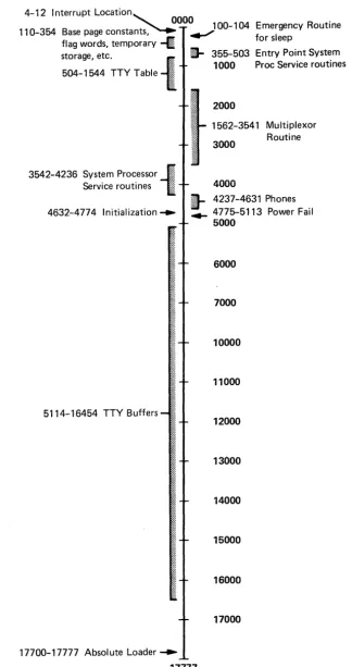
2-6 Core Map Communications Processor
Figure 5 shows the core map for the Communications Processor. It is drawn approxi-mately to scale. The small percentage (of core) required by the actual multiplexor software is rather interesting. It is apparent on this figure what a large part of the available 8K memory is dedicated to the TTY Buffers. A significant unused portion exists under the loader. It can be used for software additions or additional features (through the contributed library).
2-7 Phones Routine
4-i 2 Interrupt Location
, 0000
110-354 Base page constants~ ....) 00-1 04 Emergency Routine
flag words, temporary ~ for sleep
storage, etc. .. ~ 355-503 Entry Point System
504-1544 TTY Table
t
1000 Proc Service routines3542-4236
~yst~m Pro~essor -I~~~~l
::>ervlce routines ::::: :::::4632-4774 Initialization . . .
5114-16454 TTY Buffers
2000
1562-3541 Multiplexor
3000 Routine
4000
I-
4237-4631 Phones. . . 4775-5113 Power Fail 5000
6000
7000
10000
11000
12000
13000
14000
15000
16000
17000
17700-17777 Absolute Loader .... 17777
FIGURE 5. CORE MAP
[image:25.620.147.472.87.701.2]The routine still provides the servicing for a new call in, a user hang up, and an unsuccessful log on. A new function required in the 2000B and C is the timing for the ENTER statement. The actual timing for this routine is non-critical.
Most of the Phones servicing is done with the interrupt system enabled. This
allows the multiplexor and System Processor communications to interrupt. In effect, this routine makes use of the chinks of time that would otherwise be spent waiting in the idle loop.
It should be apparent to the reader that the time required to service the phones for log on and hang up is quite small. Consider all 32 users being serviced by the phones routine on a 3 minute basis. Statistically this would require handling one call in and one hang up (or time out) per interrupt. This is a low duty cycle. A more common environment might be CAl in which many users were being timed for ENTER statements.
Refer to Figure 6 for the detailed Phones Block Diagram. The first page gets the new data from the phone board. It compares it with the previous data and determines changes. The changes imply either a new call up (or end of line dropout) or a hang up (or line dropout). The routine then processes the*;;atus word and sets the timer value for timing.
When all changes are processed the procedure is repeated for the second phones board.
The second part of the routine services each of the 32 users. It looks at the status
I
word for four conditions: Line Dropout, Log On, ENTER timing, and Hang Up.It initiates communications to the System Processor for ENTER time out .
.!l
interprets a line dro out which exceeds 2 seconds as a hang up and initiates
l
communications to the System Processor. T e ystem rocessor respon s withthe Hang Up command when the output message is completed. .
EMXQ P54/.tt5
CLF 0 hold interrupts TMCF Save Status pointer T2 TMNH Increment PHON TMCHK Repeat
servicing Set counter
for 2nd for 32 board users
"ENTER"
YES
Restore Registers
Check Status for bits 4,5 phone timing
B =>STAT
STF 0
enable interrupts Already timing ISZ TIMO TMCA
CLF 0
Hold interrupts
Check Status for bit 4
bit 5 bit 6
bit 7
Return JMP PHP,I
ISZ PHON
Line dropout Log on ENTER timing Hang up
Send ETO communications to System Proc
TMZK Remove bit(s) from status TMLG
NO Log off Make up
) - - - -__________________________________ ~~~ ____ ~UHU code
STF 0
Allow interrupts
B => next user inc user counter
Set Status pointer Remove ISZ from LADDR TMHU
Log on timing timed out
Send to System Proc
"ENTER"
TMCHK
Set counter for 32 users Restore Registers Start again servicing phones Check Status for bits 4,5 phone timing
B =>STAT
STF 0 enable interrupts
Already timing ISZ TIMO
TMCA
ClF 0 Hold interrupts
Check Status for bit 4 Line dropout bit 5 log on bit 6 ENTER timing bit 7 Hang up
Return JMP PHP,I
ISZ PHON
Send ETO communications to System Proc
TMZK Remove bit(s) from status TMlG
NO Log off Make up
__________________________________________________________________________________ ~~UHU
code
STF 0
Allow interrupts B
=>
next user inc user counterTMCG Set Status pointer Remove ISZ from lADDR TMHU
Log on timing timed out
Send to System Proc
Clear CCNT ensure empty buffer
Add bit to PH01 disconnect lOA bit 3 Finish up Output data to phones Add stop
.--_ _ _ ... bit to
Add bit to PHO disconnect YES MPOUT Add stop bit to MPOT1 lOA bits 4,5,7 Update old data with new Set IOTOG for input
Set IOTG1 for input
Add -88 to interrupt counter Clear INPTF allow servicing Clear INPTY allow servicing
[image:28.1229.75.1189.68.726.2]SCH43 In MPX routine restore registers ISZ PHC
B =>MASK clear previous bit-shift
Line dropped out or hang up
FIGURE 6. PHONES BLOCK DIAGRAM SHEET 2 OF 2
2-16
EMXP
JMPEMXP Save registers
Check Status for bits 4,5 Line dropout
P53/#5
or log on timing
again
req, sel'YiC(! SCHP
~I
...
emask~Add bit 4 (Line dropout) to Status
Determine data bit
YI
for this . userIgnore
PHON = -21 for 2 second timing
Get return address from MPXNT Save in PHP
SCH47
STF 0
allow interrupt ClF MPX to allow interrupts EMR STF 0 enable interrupt system
Ringing +
B =i> Mask A = Data bits
Get new data ignore IG users Save data in PHN
Momentary line
drop out Remove bit 4 from Status now OK
Check against PHl for any changes
Set PHON
timing vaive Repeat Process
for 2nd
board
Set Status bit 5
[image:29.1224.72.1088.130.702.2]CHAPTER 3
PROCESSOR COMMUNICATIONS
3-1 Processor I nterconnect Kit
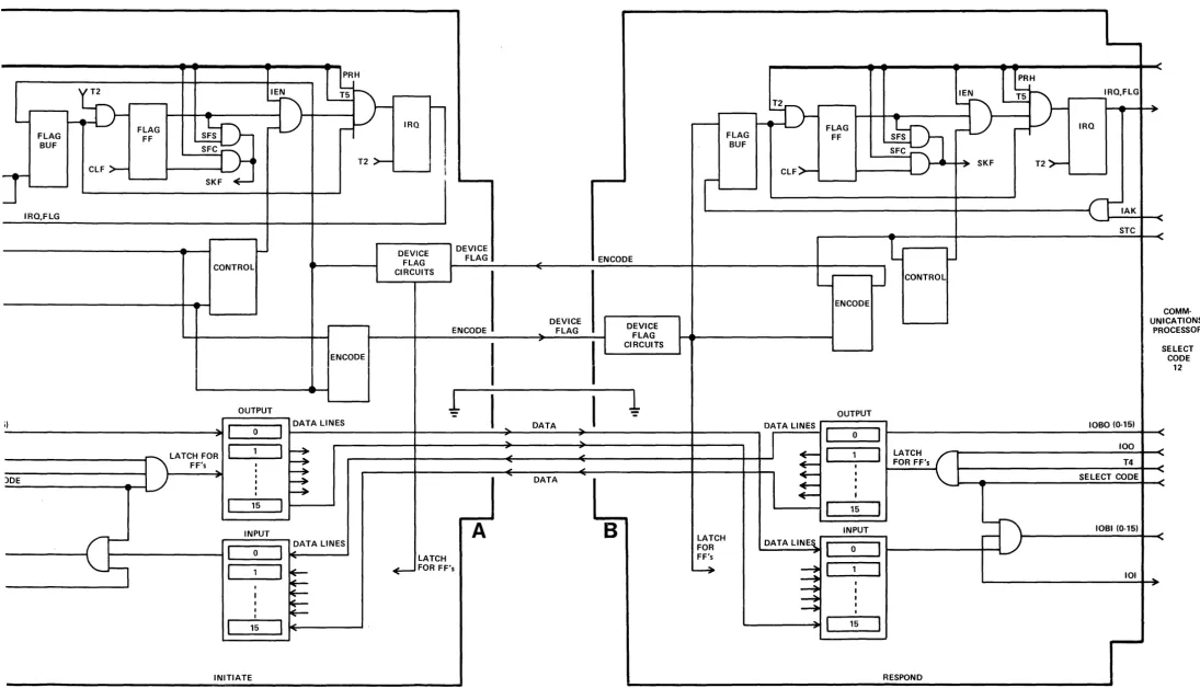
Figure 7 shows the block diagram for the System Processor initiate communica-tions channel. The Communicacommunica-tions Processor initiate channel is identical except that its select code is 13 and the System Processors select code is 10.
Figure 8 shows the Logic Diagram in which the optional circuitry and unused jumpers have been removed. All four of these 12566-6001 assemblies are identical.
We can trace through the circuit operation of the interconnect kits. The first operation is to place the request code word in the output buffer. This is done with an OT A SC
=
11. This places the data word on the lOBO lines. The 100 computer signal is gated with T4 and latches the data in the output flip flops.The actual transfer is accomplished with a STC 11 ,C. Dotted lines on the logic diagram show these signals. The STC sets the Encode signal which becomes the Device Flag to the Communications Processor. This in turn causes the data to be placed in its input register, and produces the interrupt.
When the Communications Processor acknowledges with its OT A and STC
12,C this generates the Device Flag signal. The device flag is a positive to negative transition. This is inverted and filtered by MC 87 A, R61 and C3. The rise time is improved with MC 87C,D. This positive transition then actuates two "window" type circuits. These circuits produce a negative pulse of short duration. Notice the MC 86C input on pin 13 goes positive right away. The signal on pin 12 is
positive but going negative at the rate determined by the R66-C5 time constant. This produces a narrow negative pulse from MC 86C and also MC 85B. MC 86C clears the Encode FF allowing the Device Flag circuitry in the Communications Processor to stabilize before the next command.
The MC 85B signal latches the input data in the flip flops, and also sets the Flag Buffer. Notice however the Flag FF must be cleared or else the Device Flag signal is ignored.
The System Processor cleared the Control right after sending the request. This prevents an automatic interrupt. The System Processor will test the Communica-tions Processor acknowledgement with a SFS signal instead.
3-2 Communications (System to Communications Processor)
The System Processor can initiate requests and commands for the Communica-tions Processors. Two of these are of general nature (i.e., not limited to an individual user). They include PHO to establish the phone log on time limit, and INI to initialize the new system. The other commands are user oriented (the TTY number is specified).
The user commands are associated with the buffer, with hardware control, and for general status. The hardware control includes ECO and ECF for Echo control, and FAS and SLO for terminal speed. Buffer control includes OCR, output a character, and GTC, get next character, for actual data transfer. It uses SBP to place the buffer pointer, RBP to restore the buffer to the start, and BKS to backspace a single character.
The general status includes NUC, a new user called up, ULO, user got logged on, and HUU, hang user up. The user system status includesUIR, user is running, UNR, user not running, IWT, Input wait, OWT, output wait, and STE, start timing for an ENTER statement execution. KAO allows killing a user for Break or Sleep execution. IBF checks if the buffer is full for the Announce command. IPF allows the System Processor to determine whether the user is in fast mode. The final three include TPO, tape mode, ILl, a check for a command entered during tape mode being valid, and ALI to request more input if available.
Table 2 shows the list of available commands. The actual location in listing from where the command is initiated is shown. This will help in tracking down the actual coding and processing involved.
Each command is described both with words and with a flowchart. These will be helpful in gaining an intuitive feel for the system operation and especially for the use of the TTY tables and buffer.
3-3 Code Format
...
.. IAK
,>-+--....
~
CLF~
STC
... CLC
-FLAG BUF
IRQ,FLG
CLF
>-FLAGFF
lEN
--~
~+-+-.-~---~I
,
J-r,
~LJ
~.
-SKF ~
-CONTROL
PRH
~D
-T2
>-
--IRQ DEVICE FLAG CIRCUITS DEVICE FLAG-r
ENCODE FLAG BUF 2:h~---4....-t...r
FLAGFF
CLF>
-ENC SYSTEM PROCESSORENCODE
..
DEVICE
FLAG DEVICE
FLAG CIRCUITS SELECT CODE 11 ...
,. lOBO (0-15)
OUTPUT
-ENCODE
I
I
~
ou~
::' ==0=:::'
I-D_A_T_A_L1_N_E_S _ _ _ _ _ -+ ______ ---:: ... __D_A_T_A_---::~---~I__-
_ _ _ -. DATA LINESC
... 100
~
LATCH FOR ... 1 _ _ 1 _ ... 1~
- ' "!::
c:::
...
> - - + - T - 4 - - - I , F F ' s I ~ - . J I '
....---~:--+-S-E-L-EC-T--C-O-D-E---I J ~ : ~ ~ DATA ~ ~
..
. . . / :
~
:=
.., lOBI (0-15)
10!
...
...
1 _ _ '5_~1 1 - - - ' ' - - -...
c:::
--
INPUTDATA LINES
I---~
I
0I.,
:::1==,
:::::::::1~
--~
~
....
1 __
'_5 _ ....
1
~INITIATE
LATCH
-E-- FOR FF's
A
B
LATCHFOR FF's
---
U\ DATALlNE~C:::c:::
:::
--+
FLAG BUF
IRQ,FLG
CLF
>--FLAG FF '--_--J -CONTROL PRHIRQ
-FLAG BUF
.!h
~...t..r FLAG
FF
~H
lEN T 5 )
-~I\ ~
r - + - + - e _ - - - I
s1s-rh
LJ
r-T2
>--
~l
J
~~I-~~ SKFT2>-ENCODE
CLF>- 1---1
--
'--_--JDEVICE DEVICE
l~--"'I-FLAG FLAG .; ENCODE
~~--~'---~---I--~J
----':1
RCUITS-ENCODE
..
DEVICE
FLAG DEVICE
FLAG CIRCUITS ENCODE CONTROL IRQ,FLG
....----,
IRQ '--_--J IAK STC COMM-UNICATIONS PROCESSOR i)I
'
I
~1----;~I~O~-U_T-o_P~U-T~~'-~-D~A~T:~~~L-~-E-S
____ I ______ -+ _____ JL_-______I~:~---D-A-T-A--~:~I---JL-~---~----
____~DATALINES ~I_O_U_T_:_U_T~I
r-_______________________________1_0_B_0_(0_-_15_)-.--<~
_ LATCH FOR
I
1I
~
~
""-
!=
I 1 I LATCH 100SELECT CODE
12
---...---... F F's I ; - - - " 7 " ' . ; ...--- '--- - I _ ... - FOR FF's T4
- ) D - E - - - I
U
:-
:
::::
.,
DATA : : : SELECT CODE- - - -.... --1 : ~
+ - :
-I
... _ _ 15 _ _ 1 ~----' ' - - - I
I
15I
L.!::::===.J
-
-INPUT INPUT
DATA LINES
1--_ _ _ _ _ _ -1 ::'
===0==:::::1
~
LATCH+--
FOR FF'sA
B
LATCHFOR FF's
DATA
LlNE~1 ~
_ _ o ___II---....
r---IU
- - _I _ 1 _ _ 1
+-t:
;:
1 ___ 15 _ _ _ 1 ~
INITIATE
::::1
1I
::t
:
-+
:
~
I
15I
RESPOND
lOBI (0-15)
101 ...
[image:34.1230.0.1096.78.706.2]IC K
PRH
23
ER FF
FF
SFC SFS
_ _ _ _ +-5;.. 25
R68A R70A
I.5K I.SK
-2V
IRO FF
IAK
10
R68E
I.5K
.... .-JINI..-- -2V
"
PRL
FROM
COMPUTER OUTPUT REGISTER
r---_=
lOBO IS -.!.74~_ ... _ _ _ _ ... -.!.r.-::::-::--=-::1
~~I~
i -
U3- ; ; : - 'U25RI
IK .---~~- +4.SV
T5 TO + +
~
ENF -r--"-i
IFROM
U37CI
-2V RSO 316
FLAG
R49
196 14 unA
}-';.:3 _ _ -i"::"-'_ FLG
U27B
}-=----i-=--IRO
2V
II
}-=-~~ _ _ ~':..:9_ SRO
U26A
SFS OR SFC
lOG I : I
STC,~L5; :
H ,
I: I I : I
SIR~
: : : : I I
100:
I l l : :
; : : I
101~ 13
1,2
~---r~ SKF
24' } ALL SIGNAL
k -_ _ -J:..:B~B_. RETURNS
+4.5V R52 lK
I
I
I
I
22"}
DEVICE COMMANDZ·
L
lOBO 9 -256~-"'----1-""'-='iI--::=:--l-"':"'~_-'-1 lOBO 8
51
lOBO 5
ALWAYS ENABLED
100 (DelAYED) 10l(BI
TO OEVICE
~--... - - + _ BIT 15
... - -... - - - - ' -__ BIT 14
~--... --+--BIT 13
p.
... - -... - - + __ BIT 12
~--... - - + __ BIT 11
.. - -... ---r--BIT 10
L'
... - - _ - - + __ BIT 9
... _ _ ... _ _ --'-K-<·~ BIT 8
J' BIT 7
... - -... - - + __ BIT 6
~----<IP---... - BIT 5
... _ _ ... _ _ +E_·~ BIT 4
. . _ _ ... _ _ -'-'D~·~ BIT 3
~--... --+C;;..+~ BIT 2
... _ _ ... _ _ +B:...·~ BIT 1
A'
... - -... - - + __ BIT 0
+4.5V
FROM DEVICE
BIT IS _·..:.'6=+_ ... _ _ --4~-... ___i
BIT 14 ....:..::,.-... - - - - 4 t - -... ~
• 14
BIT 13 --+-... ----4~-.... __l
"13
BIT 12 - - L -... --_4~-... __l
" 12
BIT II - - + -... --_4~-.... __l
'11
BIT 10 - - L -... ----4~-... --l
BIT 9 _"..:.'=.O -I--e----+---<It--;
" 9
BIT 8 --+-... ----4>---... __l
Hi T 7 -c" 84 _ ... _ _ --4>--_ .... ---1
• 7
BIT 6
BIT 5 --.:' 6=+_ ... _ _ --4>--_ ... ___=_;
BIT 4 - ' - . - -... --'--4>---... ---1
"4
BIT 3 - - + - _ - - _ 4 > - - -.... __l
BIT 2
---r-_--_--....
__lBI T I ---:' 2=+_ ... _ _ _ >---.... ---1
BIT 0 -".:..' L-_---... ---i~"-I
R67
10K (NOTE 4)
+4.SV
INPUT REGISTER
DEVICE FLAG
U94 lK 2V--'V'\./\r--e VIla 11 U74 lK 2V --'INI~+--e
11
2V 11
V115
2V 11
V115 U54 IK U34 IK 101'se U84B 8 U94A 14 U94B 8 U64B U64A 14 U74A 14 U44B B 14 U54B U24B 8 U34A 14 U34B TO COMPUTER 83
l-=---I~ .. IOBll!)
lOBI 14
r'.::.3 _ _ _ _ t -79_ lOBI 13
lOBI 12
50
lOBI 11
13
lOBI 10
13 28
~----r--lOBI 9
27
~----+-- 10818
84
lOBI 7
81
IOBI6
13 80
~----r-_ 10815
77
10BI4
64
I - " - - - i l - - l .. iOBI ~
30
~---~~~iOBIZ
13 29
~---iH" lOBI 1
26
Figure 9 shows the use of bits in the command code word.
15 14 13 12 11 10 9 8 7 6 5 4 3 2 1 0
CODE TIY# CHARACTER
15 14 13 12 11 10 9 8 7 6 5 4 3 2 1 0
1 1 1 TTY
#
SUB-CODEFIGURE 9. COMMAND CODE FORMAT
3-4 Command Initiation
The commands in this section are initiated by the System Processor. We would like to develop an awareness of the philosophy as well as an understanding of the actual hardware. Figure 7 shows the hardware block diagram for Inter Communi-cations. The 4 processor interconnect boards are identical (only 2 shown). Each has standard Flag and Interrupt circuitry. Each has 16 input and 16 output lines.
The output data is latched in the FF's with an OTA or OTB instruction. The input data is available through the cable from the other processor. The Device Flag signal latches the data FF's as well as setting the Flag and IRQ circuits. The in put data is available through a LIA or LIB instruction. Notice these boards are cross coupled. The output of one becomes the input of the other, and the Encode out becomes the Device Flag input to the other.
Let's back up now to get an over view of the system. The System Processor initiates these communication requests from various places: Scheduler, basic syntax check, syntax execution and library coding. The TTY number is combined with the request code. In the four cases in which data is required (OCR, STE, PHO, and INI) it is added to the request word. The data is output to the I/O card. The actual transfer takes place when the STC11 ,C is executed.
Only two commands require an answer in the 2000B (IBF and IPF also require an answer, but they are used only in the 2000C system). INI is easier to wait for than to provide coding to test its completion. It also determines that the Communications Processor is operating. GTC gets the next buffer character. The System Processor must wait until the character is available. It does so with a SFS 11, JMP*-l. Now for all other commands the system can continue its processing. But it may be essential that the previous command be executed before continuing.
The Commu.EicatA~_1},~grocessor sits inj.t.~jgle loop except when servicing multiplexor
(m-'ph~~;~): Th~ com~unicati~-~~'~~terrupt'-~;y'beheraolf by-the·mul1:1ple~~r-·· --prC:Ces-Sr~g due to its lower priority.
I
I
TABLE 2
SYSTEM PROCESSOR TO COMMUN ICATIONS PROCESSOR REQUESTS
MNEMONIC CODE DEFINITION
System Communications Processor Processor
*OCR (HTT) 000000 Output Character
*STE 020000 Start ENTER Timing
GTC (GMA) 040000 Get Next Character
*PHO (PHS) 060000 Phones Tim ing
BKS 100000 Backspace in Buffer
SBP 120000 Save Buffer Pointer
[(FBP) an alternate mnemonic for SBP]
RBP 140000 Restore Buffer Pointer
LISTING REFERENCE
P247/:/f2.0 L 146
Pl0lf.#8 L 38
P185/#14 L 652 P237/#19 L 338
P2461#20 L 87
P416/#33 L 389
P184J#14 L641 P241/#19 L 557
P246/#20 L 104 P26!#3 L 248
P57/#5 L 22
P26/#3 L 248
P58/#6 L 77
P26/#3 L 263
P58/#6 L 89 MIKRO 160000 Additional requests encoded using bits
**INI (lNIF) 160000
UIR 160001
UNR . 160002
IWT 160003
HUU 160004
ULO
I
160005
ECO 160006
ECF 160007
TPO 160010
* bits 0-7 contain an output character
** bits 0 -4 contain subcode
0-4 as follows
Initialize System P234/#19 L 162 User Is Running P62/#6 L 249 User Not Running Pl05/#9 L 210 Input Wait Pll0/#9 L 419 Hang User Up P303/#24 L 445 P360/#29 L 64 User Logged On - I P297!#24 L 154 stop auto disconnect
I
timing
Echo On P303!#24 L 442
TABLE 2 (Cont)
SYSTEM PROCESSOR TO COMMUNICATIONS PROCESSOR REQUESTS
MNEMONIC CODE DEFINITION LISTING REFERENCE System Communications
Processor Processor
III 160011 Any Illegal Input P238/#19 L 378
NUC 160012 New User Called P295/#24 L 45
KAO 160013 Kill All Output P359/#29 L 30
ALI 160014 Allow Input (LF) P54/#5 L 381
syntax tape mode P237/#19 L 341
OWT 160015 Output Wait P248/#20 L 188
FAS 160016 Fast Terminal P417/#33 L 440
SLO 160017 Slow Terminal P419/#33 L 458
IBF 160020 Is Buffer Full ***
IPF 160021 Is Port Fast ***
*** These two commands are used in the 2000C only.
We can now understand the command initiation block diagram in Figure 10. The request word is made up of the code, the teletype number and the data character if necessary. This is all accomplished within the initiating routine.
It then transfers to the S 14SH routine for the actual communications.
It may be necessary to wait for the acknowledgement of the previous request. There is a little house keeping necessary to allow for this wait. Flag (/)
is cleared to hold off interrupts. The A and B registers are saved. The Scheduler is blocked allowing time up-date but no new entry to the scheduler from the Time Base Generator. Now the prior acknowledge is checked. The system waits until this acknowledgement arrives. ,The Flag '/) is set to. allow interrupts during this potential wait. The Communications Processor responds with a STC 13,C. This Encode signal acts like a device flag to the board in SC 11. The System Processor tests with a SFS 11, JMP*-l.
When the acknowledgement is available the System Processor sends the current code with an OTA 11, STC 11,C. The OTA places the data in the output register. I t is immediately available to the Communications Processor board. The STC gives the Encode. This Device flag to the Communications Processor latches the data in the Input register, and initiates an interrupt to select code 12. The System Processor then clears the Control on select code 12. This is done to prevent an interrupt. The only command requiring an immediate answer is the GTC. This is awaited with an SFS 11, JMP *-1. The others are not critical so long as they are accomplished before the next System Processor request.
The B register is restored. The entrance to the scheduler is restored. The program returns to the initiating program.
The Communications Processor responds to the communications request interrupt and saves its registers. It determines the TTY number. It determines the request and the starting address of the actual request servicing routine. It acknowledges the completion of the System Processor and restores the registers. It then return.s to the point of execution at the time of interrupt. This will typically be the idle loop or phones routine. The multiplexor is usually executed with the Interrupt flag cleared to prevent interrupts.
SYSTEM PROCESSOR
Within routine desiring a Comm Proc request
lOA with request code bits 13-15 (if macro also bits 0-3)
insure
acknow-t--...,r-llN ledgement from previous request
COMMUNICATIONS PROCESSOR
Interrupt
S.C. 12B from
~
System Proc.CMRTN
STF 0
CMI Save registers Restore registers
....
Add user TTY number in bits 8-12 NO LlA request STC,C acknowledge receipt add data bits 0-7
OTA output request code SC = 11
4
Save request SVC1Return JMPCMI,I
JSB S14SH
STC,C initiate interrupt in Comm Proc
Get TTY #
....
shift and mask B =>BTIMS14SH
P226/#18 ClF 0 hold off A-register
= request code interrupts
ClC inhibit acknowledgement interrupt
Get request shift and mask it
...
to get routine starting addressRestore B-register
....
JMPto subroutineE = 1 upper 16 TTY's
Sav A and B registers
ClF 0 hold interrupts
4
ClF 0restore JMP or NOP clock entry to Scheduler
Block clock entry to Scheduler
-+
Service requestSTF 0 allow interrupts
STF 0 return JMP S14SH,I
FIGURE 10. COMMAND INITIATION (SYSTEM PROC. TO COMM. PROC.)
3-5 Command Definitions System Processor to Communications Processor
OCR - Output a Character
This command is initiated from numerous locations in the System Processor software. It is necessary for all output to the user including Basic program execution, error messages and command execution. The actual character to be transmitted is placed in bits 0-7 of the request code word.
The Communications Processor service routine determines whether the user is already set up in output mode by the bit in IOTOG. If so it checks for buffer full condition. It initiates the BFL for a full buffer condition. This results in an output suspension by the System Processor. It then updates the CCNT by adding a negative 1. It checks for buffer wrap around condition. I t then places the character in the TTY buffer and updates the BSTR pointer. For an initial output character it must insure no input is currently underway. It does this by looking at the LADDR entry for an ISZ entry. It allows either 20 or 100 interrupts to insure adequate sync time for the TTY. (The rotor must be in stop position before starting the next data character). The various TTY table entries are initialized and the character is appended to the buffer.
STE - Start ENTER Timing
When an ENTER command is being executed the maximum response time is specified. This specified value is transmitted through the request code bits 0-7. It is placed in the TTY table entry ATIM. Its 2's complement form is placed in TIMO. The value ofTIMO entry is incremented during phones routine. A comparison ofTIMO and ATIM at the input carriage return gives the response time. A rollover of TIMO before the response carriage return indicates time out condition.
This request also sets the ENTER timing bit and removes the No Input Allowed bit from the user Status entry.
GTC - Get the Next Character
The System Processor initiates a request whenever it requires the next character from the TTY buffer. After initiating the request the System Processor waits on a SFS Select Code 11.
3-12
PHO - Phones Timi!!B
..
The phones servicing is handled by the Communications Processor. The log on time limit is established by the system operator. This new value is converted to one-tenth seconds and stored in the 2's complement form. The phones routine is entered ten times per second (88 multiplexor interrupts).
BKS - Backspace the Buffer Pointer
The System Processor sometimes requires that the buffer pointer BHED be backspaced. The Communications Processor decrements the pointer after taking care of possible buffer wrap around.
A good example of the backspace command occurs in the scheduler. The input line is checked for a null line, syntax, iiivalid command or valid command.
If the line is syntax this is determined by the first character lying between ASCII 60 and ASCII 71. Now the user is scheduled for Syntax and the buffer pointer is backspaced to the beginning of the full line.
SBP - Save Buffer Pointer
The BSAV entry points to the beginning of the current input line being processed. The BHED is advanced through the character string pointing to the current char-acter being processed. On occasions it is necessary to reset BHED to the beginning of the line (refer RBP request).
The function of BSA V was performed by a location in the Swap area for the 2000A. Now it is more convenient to provide in the Communications Processor.
RBP - Restore Buffer Pointer
This request allows the Communications Processor to reset the value of BHED to BSAV. The Basic Syntax coding requires a different technique in evaluating a GO TO absolute value compared to a computed GO TO formula. The Syntaxer approaches this as a branching problem. After determining the type it restores the buffer pointer and continues with the statement processing. The other times the Restore Pointer is used occur in GO SUB and multicharacter symbol table search.
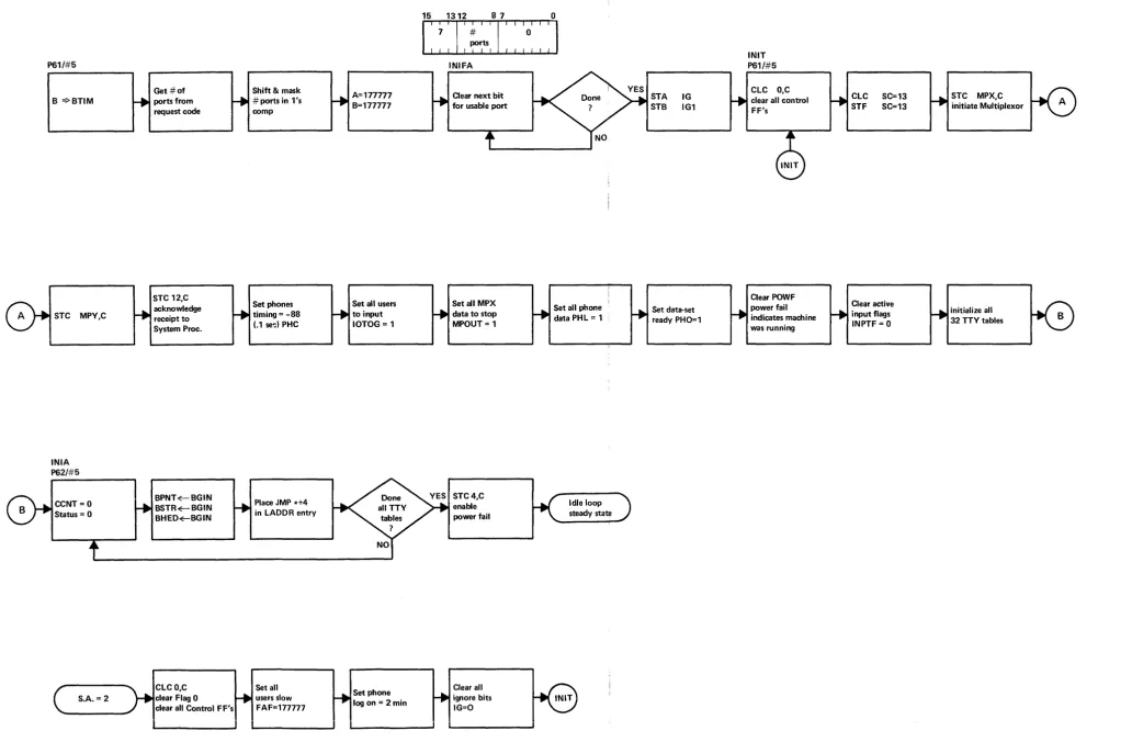
INI - Initialize System
When the System Processor is initiated from paper tape load or reloaded from disc or mag tape sleep it commands the INI Initialize Communications Processor system.
The initialize program when started at starting address = 2 resets all users to 10 cps, and resets the phone log on time constant to 2 minutes. It then proceeds at INIT P61/#5. When the System Processor sends the request the fast ports are not changed and the phone log on timing is not changed, but the actual number of allowable ports are set up in the corresponding Ignore IG and IG 1 words. At this point both initialization programs continue at INIT.
The IN IT program sets up Control FF's on the multiplexor boards and send channel. It clears Control on the receive channel. It establishes base page words for input flag, multiplex output stop bits, and phone data. It allows power fail interrupt.
The teletype table entries are established. These include the entries associated with the TTY buffer pointers, and status.
When a Time-Share system is up and running and the Communications Processor program is restarted at starting address 2 additional overhead may be introduced ;nt-A t-h.,. C"'UCTPTYl
~.l. .... '-' "'.1J.""" ~ J ~"'''''''~'&.L.
This occurs when not all 32 users are in use. It is especially noticeable when only one multiplexor board is installed. This is due to clearing all the Ignore bits. The multiplexor board inverts so that all inputs are high when no mpx panel is connected, or no user terminals are connected. But when no mpx board is installed all inputs are low. These look like start bits and require mpx processing.
UIR - User is Running
This command is sent when the program is being compiled for program execution.
It prevents all user input except abort.
UNR - User Not Running
At the completion or termination of program execution the run bit in the status word is cleared and No Input Allowed bit is cleared allowing any input (not just abort).
IWT - Input Wait
$I
3-14
HUU - Hang User Up
This request removes the user from Run status, and sets bit 7 indicating a hang up is desired. The hang up is performed by the phones logic. The command is initiated by the user with the BYE command, or by the system operator with the SLEEP command.
ULO - User Logged On
This command is initiated by the HELLO library routine which indicates the user satisfactorily logged on and has time available.
If this were not cleared in time it would result in a disconnect signal to the phones board. It does ·not affect hard wired terminals.
ECO - Echo On
The Echo bit PLEX is used by the multiplexor to determine whether the output multiplexor data is updated for this user. This command resets the corresponding bit. This results in all incoming data bits being sent back to the users terminal. The 2749A Teleprinter requires this data for the character to be printed locally, thus the Full Duplex mode is normally required.
ECF - Echo Off
This command removes the users bit from the PLEX word. This bit is used by the multiplexor to .determine whether the incoming data bits must be sent back to the terminal.
The TBX equipment (teleprinter and telephone networks) conserves phone band-width by printing the chara~ter locally and thus avoiding the requirement for the returned signal. Echo Off is primarily used with this class of terminal.
TPO - Tape Mode On
This command sets the status bit indicating tape mode. Tape mode is a special multiplexor operating condition. It is used to load Basic source programs through the TTY reader.