Real Time Wireless Surveillance System with Motion
Detection and Device Control over Internet
Munyaradzi Rushambwa, Tinashe Chamunorwa, Kumbirayi Nyachionjeka
Electronic Engineering Department, School of Engineering and Technology, Harare Institute of Technology, Harare, Zimbabwe.
Abstract- A low cost High Definition (HD) security surveillance system with motion detection and device control over the internet is explained in this paper. The system is reconfigurable and can be applied to many applications. However for the purposes of this project a system configured to monitor a home and home devices is explained. Further reconfigurability can make the system suitable for use in military surveillance, bank vaults and locker rooms, shopping malls and authenticated areas depending on the devices to be controlled. The real time surveillance is carried out by the D-Link DCS 930 IP wireless camera that works with both Wi-fi and Ethernet connection. The camera is powered by both mains supply and battery which then makes it suitable for continuous surveillance monitoring. An integration of the camera with a motion detector is also done to be able activate notifications (video, images and sound) that are sent via mail and in case of bad internet connection it uses the Subscriber Message Service (SMS) platform which is controlled by an Android application. The controlling of devices over the internet is done using a micro-controller which is used to provide communication between the devices to be controlled and the internet over a software interface designed using the web server concept.
Index Terms- Android, High-Definition, Internet, Subscriber-Message-Service, Surveillance, Web-Server, Wireless.
I. INTRODUCTION
urrently there are a variety of security systems that are used in the world in different applications[1]. Applications of security systems ranges from bank vaults, base stations, military, ATM's, Jewelery shops and authenticated regions. With the increasing need of security systems in the areas there has been many systems developed over the past decade[2]. Most of these surveillance systems uses video cameras including analog CCTVs and many other devices. These systems perform real time continuous monitoring of the environment in question and some of them uses the wired system to transfer the recordings to an external DVR storage[3]. Which means when something happens one has to be physically on the site and replay the video recordings. Another thing is that most of these systems rely on the mains power for them to to fully operating.
In this 20th century there has been a significant change in technologies that has lead to a high demand of high quality surveillance system[4]. Picture a situation where one can monitor his home wirelessly on a real-time basis, having the video clips and images only when motion is detected sent to him over the internet to his email. Yes its possible but one might ask what if
there is no internet connection and no power. The question does not stand since the system visualized has the ability to send an SMS when motion is detected and capture the image of the motion scene and store it to the SD-card on the system. A battery powered camera is an exception to such a system since it can work whether there is power or not. In addition to the surveillance how about controlling the devices that are at home using the internet from any location? . That is pretty smart and with the issue of the Internet-Of-Things (IOT), this would really make life easier for most people.
The system visualized above was developed and yes it will improve the life of many people. The hardware and software specifications of the system are explained below.
[image:1.612.338.550.366.550.2]A . Hardware Overview
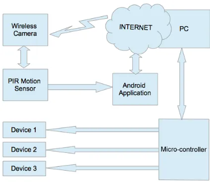
Figure 1. The system block diagram
Figure 1 above shows the block diagram of the system implementation. The wireless camera (D-Link DCS 930L) is connected to the internet over a Wi-Fi network that is configured on the computer and can be placed anywhere in the surveillance area. The camera records video clips with audio and takes images when motion is detected. The images are then sent to a configured email address or alternatively stored on the SD-card. The camera is mydlink enabled and thus one can check the camera at any given time from a remote location[5]. Also when motion is detected the PIR sensor invokes certain events to take place through an Android application.
When there is motion that is detected whilst the system is activated the Android device sends a notification message to the owner and also takes images of the event and stores them separately for redundancy sake. When the system is deactivated the image is not captured for saving space and the notification messages are not sent to the owner. To activate the system the owner has to send an encrypted SMS to the Android device and upon receiving the message, the Android sends back an acknowledgement that the system has been successfully activated. In case an anonymous person tries to activate the system, an alerts message is sent to the owner from the Android device with the message showing the SMS contents, the sender's cell ID, the date and the time the message has been sent. To deactivate the system , the owner has to call the Android device using only his number which is recognized by the Android application.
In case someone tries to deactivate the system, a call log message is sent to the owner showing the caller's cell ID the date and the time that the system has been called. Through an application that is developed using visual basic software the user can also manage and control devices that are at his house over the internet. The application monitors the state of the devices and updates it on the web interface.
[image:2.612.63.266.343.540.2]
B. Software Overview
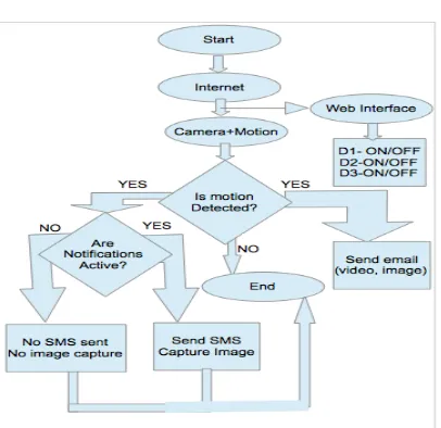
Figure 2. Software flow
When the system is started it searches for available internet connections and does not do anything until a connection is established. Firstly the web interface controlled by a windows software developed using http web sever scripts , is set active. When the web interface is active and accessible it means we can
are now able to control home devices. The second condition is the connection of the camera and the motion sensor to the internet, when they are connected the system now waits for motion to be detected. When motion is detected also two events are triggered. The first event to be triggered is the sending of the video clip and the images taken by the camera to the configured email address. Secondly when motion is detected the system checks whether the Android notifications are active or not. When the notifications are activated, the Android device, when motion is detected captures an image and stores it separately for redundancy. It also sends an SMS notification to the owner notifying him of the event. When the notifications are deactivated , the Android device, when motion is detected does not capture the image and also does not send an SMS. For the devices there is need to load the server application software using the Arduino board and the ethernet shield. Once a gateway has been created between the firmware and the web server via the ethernet shield the user can now communicate with the devices over a TCP/IP protocol stack. For system optimization static IP addressing is used over the conventional Direct Host Configuration Protocol(DHCP)
II. WIRELESS CAMERA
When one wants to monitor his home wirelessly he can use a standard webcam over USB or use a smartphone as the webcam. This implementation is wired and has many disadvantages as compared to the wireless way of doing it. The wireless method implored in this project is the use of a wireless network camera which can connect to the network via a 802.11n Wi-Fi point. The camera is configured before a position to mount it is chosen. An elevated position that is close to the power source has to be chosen for the the mounting of the camera. The network from where the camera has to be installed must be tested to check proper connectivity. To configure the wireless network camera is connected through ethernet to the router that is being used. Alternatively some routers have a built in switch and it makes it easier for configuration. The camera is connected to the PC and the necessary configurations are done. Having the working wireless camera there is need to setup the motion detection features. Now when motion detection is enabled , the camera should send the images to the configured email. The email option is configured using the email provider's SMTP servers[6].
Table 1. D-Link DCS930L Features
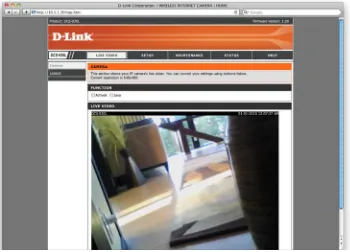
Figure 3. A Snapshot of the real time camera surveillance
III. ANDROID APPLICATION
An android application is used to provide an alternative and more secure surveillance system. The system is activated and deactivated using this android application that is linked to the motion sensor. The application is in two parts, the first part is the actual application that performs the actions when there is an external trigger effected by the motion. The second part is the API authentication kernel that is developed using MIT's App Inventor. Which mean that one has to have a password to be able to open the application. How this application basically functions is it consists of rules that are loaded to the phone to monitor certain events. Theses rules have trigger conditions and the action conditions. For this system the trigger is the connection of external power to the Android device when motion is detected. This thus performs the capturing of the image using a camera plugin installed on that phone and the plugin linked to the Android application. Also this trigger effects the sending of an
SMS to the controller , notifying that there is an intruder. The SMS contains information about the system's battery status, GPS location, google maps address, network location, date and time. This only happens when the system is activated and to activate the system a specific encrypted SMS has to be sent to the Android device. The device responds back with an acknowledgement that the system has been activated or not. To deactivate the system a specific call has to reach the system, and an acknowledgement message is sent to the controller informing that the system has been deactivated or not.
a b
Figure 4 (a). Software flow to enable the system using an encrypted SMS. (b). Software flow to disable the system using a specific call
Figure 4 (a) above is the software flow for the SMS-based activation of the system's alerts and alarms via an encrypted message. Figure 4 (b) show the software flow of the call-based deactivation of the system's alerts and alarms.
[image:4.612.78.281.78.237.2]The selection and configuration of events in the Android application follows a common flow as one that is below:
Figure 5. Rule Setting Flow
IV. INTERNET DEVICE CONTROL
The micro-controller in this project is used to provide communication between the devices to be controlled and the web interface via a software developed using http scripts and web servers. On the software is a user interface that shows the device name and the status of each device. The devices are then controlled via a web interface which is linked to the devices via a
serial communication protocol. Upon clicking the ON/OFF button of the corresponding device then responds by toggling its state.
A. Micro-controller and Device Control
[image:4.612.346.556.321.403.2]The micro-controller used is the AT89S52 that is embedded on an Arduino board and has numerous advantages over the other micro-controllers. It has the ability to send and receive data over a single wired built in USB port, supports more number of interrupts for processing, has 4 timers and a larger flash memory than the other types of micro-controllers. Of interest in this project is the ability to send and receive data over USB and the UART/USART serial communication and the easy interfacing with an ethernet end [7], a feature which is used to control the state of the devices over the internet through a web interface.
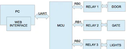
Figure 6. Relay connections to the controller
a b
Figure 7 (a) and (b) The hardware implementation of the relay control module
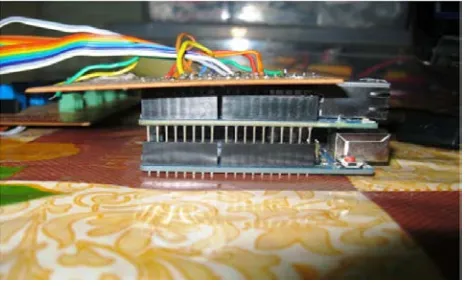
Figure 8. Arduino board and the Ethernet shield interfacing
Through the relay the micro-controller is continuously polling for the state of the devices and reports via a serial communication protocol to the web interface which is human controlled.
Arduino Digital Pin Number Pin Usage
4 Motion Sensor input
5 Output relays
6 Output relays
7 Output relays
8 Output relays
9 Output relays
10 Ethernet Shield
11 Ethernet Shield
12 Ethernet Shield
[image:5.612.81.494.69.197.2]13 Ethernet Shield
Figure 9. Shows the physical connection between the controller and the devices. Table 2. The physical connection of the devices to the controller pins
B Web Interface
The web interface is designed using visual basic and has a simple user interface that appears online for controlling the
[image:5.612.188.423.232.375.2]following the steps prompted during the installation process. When the installation and the launch is done there is need to check for serial communication connectivity between the micro-controller and the web interface. Upon toggling the buttons of either device the status box should change. A view of the web interface can be as the one below:
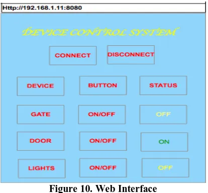
Figure 10. Web Interface
The interface shows the network address of the system and on the page there is a name of the project. However there is a button to connect or disconnect from the harware system. The connect button estblishes connection between the web interface and the hardware devices via the serial interface. Once connection is established the user can now toggle the state of the device and as can be seen in Figure 7 that the first device which is the door is off, the second device which is the door is on and the third device which are the lights are off.
V. SECURITY FEATURES
The paramount important features of such a “security” system are the “security” features. The system however has very strong security points, some of which are not explained here for some security reasons.
1. The first security feature of the system is in the configuration and installation of the wireless camera. The process requires a password and without this password no one can install the camera
2. Security feature number 2 is in the Android application which need a password when you are installing it and also every time you reopen it.
3. The third security feature is the encrypted message that is sent to the station to activate the alerts and the alarm, using only a specific number. Which means even when someone tries to activate the system with his phone when he knows the encrypted password he always fails.
4. The fourth security feature is the call that is made to the station to deactivate the alerts and the alarm. This call is only specific to a particular number and if no other number can deactivate the system.
5. The fifth security feature is the logging of messages and calls made to the system via SMS and to a gmail account. Which means that the owner can take necessary legal action to those trying to activate or deactivate the system since he has the logs. 6. The sixth security feature is the sending of images, videos and audio to a configured email address whenever there is motion. This is contrary to the conventional systems that record and stores the information on the same system a design which is susceptible to damage.
7. The other security feature on this system is the tamper and moved GPS feature. When one tries to tamper with the system or moves it to another GPS location, a message is sent to the controller informing of the new GPS location, google maps address and the network location and another message informing that the device is being tampered with.
8. The last security feature is the redundancy capturing of the images when motion is detected. For this feature this is all the information that can be provided for security reasons.
VI. RESULTS
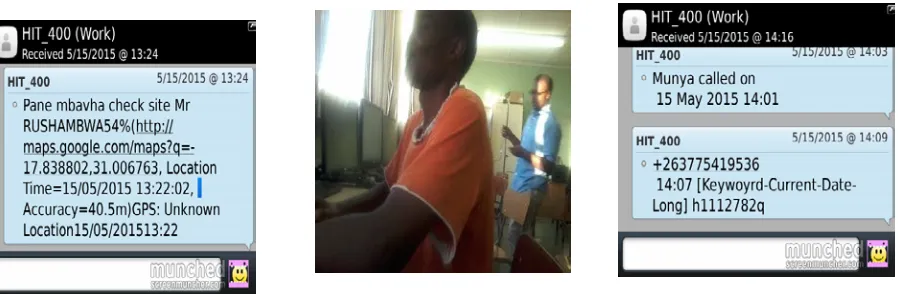
The results from such a system is a table explaining different conditions, pictures taken by the system when motion is detected and the types of messages sent by the station to the controller for different events.
a b c
Figure (a). The message sent when motion is detected. (b). image taken when motion is detected. (c). call log SMS and encrypted message activation SMS
VII. FUTURE WORK
As an improvement to this project it is necessary in the future to include a feature in which when there is motion detected the images taken can also be sent on WhatsApp. Also on the devices it is important to set the time which one want the device to be off or on. The time may be duration in which a device can be on or off for some time and toggle the state, ot may be in terms of the time one wants the devices to be on or off. Another feature that may be easily added is to integrate the whole system to a low power switching system that includes an inverter. In instances that power has gone the system should automatically switch the power source and take the inverter source.
VIII. CONCLUSION
The system explained in this paper is a robust system combining both smart home monitoring and real time surveillance. The system because of its technical complexity nurture requires trained personnel for installation and maintenance, which however creates employment on the other hand. The system saves data storage space and the issue of buying a DVR which cost way over US500 (500GB) to record everything. The system therefore is a low cost, reconfigurable, high definition and flexible real time wireless surveillance and device control.
REFERENCES
[1] Jeonghun Kim, Jeongwoo Park, Kwangjae Lee, Kwang-Hyun Baek Suki Kim, ―A Portable Surveillance Camera Architecture using One-bit Motion
Detection‖ IEEE Transactions on Consumer Electronics, Vol. 53, No. 4, NOVEMBER 2007.
[2]
[3] Bradley Hamburger, Digital Video Recoders, Advertisement Avoidance and Fair Use, Havard Journal of Law & Technology, Volume 23, Number 2 Spring 2010.
[4] V. B. Jagdale, R. J. Vaidya High Definition Surveillance System Using Motion Detection Method based on FPGA DE-II 70 Board International Journal of Engineering and Advanced Technology (IJEAT) ISSN: 2249 – 8958, Volume-2, Issue-2, December-2012.
[5] http://storagenewsletter.com/rubriques/cloud-online-backup-ssps-msps/d-link-mydlink-turns-usb-drives-into-private-cloud-devices/
[6] Sureswaran, R. Nat. Adv. IPv6 Centre (NAv6), Univ. Sains Malaysia, Minden, Malaysia Al Bazar, H. ; Abouabdalla, O. ; Manasrah, A.M. Active E-mail system protocols monitoring algorithm, TENCON 2009 - 2009 IEEE Region 10 Conference 23-26 Jan. 2009 Page(s): 1 – 6 E-ISBN : 978-1-4244-4547-9 Print ISBN: 978-1-4244-4546-2 INSPEC Accession Number: 11135058
[7] N. P. Joshi1, P.V.Patel2 Assistant professor, Dept. of ECE, R. K. University, Rajkot, Gujarat, India1 PG Student [EC] , Dept. of ECE, R. K. University, Rajkot, Gujarat, India2 , LabVIEW and Web-Server based Human Body Monitoring System International Journal of Advanced Research in Electrical, Electronics and Instrumentation Engineering (An ISO 3297: 2007 Certified Organization) Vol. 3, Issue 5, May 2014 ISSN (Print) : 2320 – 3765 ISSN (Online): 2278 – 8875
AUTHORS
First Author – Munyaradzi Rushambwa, Electronic Engineering Department, School of Engineering and Technology, Harare Institute of Technology, Harare, Zimbabwe, Email:
Second Author – Tinashe Chamunorwa, Electronic Engineering Department, School of Engineering and Technology, Harare Institute of Technology, Harare, Zimbabwe.
Third Author – Kumbirayi Nyachionjeka, Electronic Engineering Department, School of Engineering and
[image:7.612.48.497.73.220.2]