A Review on Thermal Analysis of IPMSM used in Rail Vehicle with
Water Cooling Jacket by using FEA
Irshad Ahmad
1Omshankar Jhariya
2Anil Verma
3G. R. Selokar
4 1Research Scholar
2Assistant Professor
3Head of the Department
4Registrtar
1,2,3
Department of Mechanical Engineering
1,2,3
School of Engineering, SSSUTMS, Sehore, India
4SSSUTMS, Sehore, India
Abstract— Computational fluid dynamics analysis of electrical and mechanical components is an important role for design of motors water- cooling jacket and for choosing suitable cooling system to satisfied their optimum performance and reliability. Thermal behavior of IPMSM water-cooling jacket is depends on motor geometry. Computational fluid dynamics analysis of IPMSM motor with water-cooling jacket is being analysis by using ANSYS. Initially water-cooling three-dimensional solid model has been created in unigraphic & then finite element analysis is carried out in fluid flow fluent workbench of ANSYS. It is important to have an efficient cooling for the IPMSM to generate high heat dissipations. Velocity and temperature analysis in the solid modal of water-cooling jacket of IPMSM used in railway vehicle. The results obtained shows the effectiveness of the designed of the IPMSM water cooling jacket to its thermal behavior.
Keywords: Interior Permanent Magnet Synchronous Motor, Water Cooling Jacket, CFD, ANSYS, and Finite Element Analysis
I. INTRODUCTION
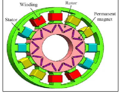
[image:1.595.65.267.591.747.2]A permanent magnet synchronous motor is a motor where the excitation field is provided by a permanent magnet instead of a coil. The term synchronous refers here to the fact that the rotor and magnetic field rotate with the same speed, because the magnetic field is generated through a shaft mounted permanent magnet mechanism and current is induced into the stationary armature. Synchronous motor is the majority source of commercial electrical energy. They are commonly used to convert the mechanical power output of steam turbines, gas turbines IPMSM machine with distributed windings typically do not generate a significant amount of heat in the rotor-roughly 90% of the motor losses tend to occur in the stator, which can be easily cooled by heat sinking, oil cooling, or water-cooling. Fig. 1 shows Interior Permanent Magnet Synchronous Motor (IPMSM).
Fig. 1: Interior Permanent Magnet Synchronous Motor (IPMSM)
The Interior permanent magnet synchronous motor for the railway vehicle is installed on the axles of the bogie, which is located on the lower part of the vehicle. Due to influence of the rail track environment, there is a large amount of dust blown during vehicle operations. However, the totally enclosed motor, which has a problem for cooling, is not a suitable structure for the Interior Permanent Magnet Synchronous Motor (IPMSM), which has a permanent magnet embedded in the rotor. Especially, in recent scenario, where the downsizing of the traction motor both in size and weight is greatly in demand, research on a separate cooling device for the IPMSM is need to have a competitive edge.
In general, there are three cooling methods for the traction motor: natural air-cooling, forced air-cooling, and forced coolant cooling [1]. Among these, forced coolant cooling has the best cooling capacity. The smallest-sized traction motor can be designed if forced coolant cooling is applied to find out IPMSM. Research on the above is essential: a) prediction of heat generated from inside the IPMSM which is designed to have high current density, b) design of cooling channel and device to efficiently discharge the heat generated inside the IPMSM to the outside, and c) a heat analysis technique to predict the cooling capacity of the designed cooling channel and device [2].
To calculate the thermal behavior of the machine ANSYS Fluent is used. This is a highly sophisticated finite element modeling and analyzing tool. It can be used to analyze complex problems in fluid and thermal processes. [3]
Thermal management of the IPSMS is important because the electrical insulation has a temperature limits, and cooling system affects its performance [6]. Therefore, in this paper, the water-cooling method among the forced coolant cooling methods is considered to can be applied to the IPMSM. Three-dimensional solid modal has been created in unigraphic & then finite element analysis is carried out in fluid flow fluent workbench of ANSYS. Then, based on the results obtained from thermal property analysis, design has been introduced.
A. Types of Permanent Magnet Synchronous Motor: Synchronous motors fall under the more general category of synchronous machines, which also includes the synchronous generator. Generator action will be observed if the field poles are "driven ahead of the resultant air-gap flux by the forward motion of the prime mover". Motor action will be observed if the field poles are "dragged behind the resultant air-gap flux by the retarding torque of a shaft load". 1) Non-Excited Motors
Reluctance motors Hysteresis motors
2) DC-Excited Motors
B. Application of Permanent Magnet Synchronous Motor: Synchronous motors are used to regulate the voltage at
the end of transmission lines.
In textile and paper industries synchronous motors are employed to attain wide range of speeds with variable frequency drive system.
Synchronous motors are used in generating stations and in substations connected to the busbars to improve the power factor.
II. NEED & BACKGROUND
IPMSM motor required cooling because this motor consist stator and rotor, in a stator the rotor is fitted when electricity is delivered in stator coil then magnetic field are generate due to magnetic field generation the stator is rotated in high speed or motion.
When IPMSM motor rotating in high speed there are in some part are high torque and friction occurring due to this friction the heat is generated i.e. temperature of a body are increased. Due to increased temperature of a body maybe coil is damage or the efficiency of the machine are decreased.
[image:2.595.46.290.202.567.2] In that conditions the motor is required some external ways to cooling its body so cooling is most requiring for the IPMSM. Of these, forced coolant cooling has the best cooling capacity. The smallest-sized traction motor can be designed if forced coolant cooling is applied to the IPMSM. However, for the application to be possible, research on the following is essential.
Fig. 2: Induction motor for railway vehicle
A. Need of CFD:
Computational Fluid Dynamics (CFD) has become an integral part of the engineering design cycle. Whether it is used to simulate industrial mixing tanks, aerospace components, or a myriad of other transient or steady-state flow phenomena a CFD analysis reduces development time, minimizes costs and increases the reliability of prototype designs.
CFD simulations can be used to model fluid flows over a wide range of physical scales. Thus, many of the same algorithms that can be used to simulate oceanic and estuarine flows can (with the addition of appropriate special models - e.g.: surface tension) also be used to simulate the behavior of micro-droplets ejected from inkjet printers.
The areas where CFD can provide cost savings and design efficiency are many. Our own studies range from the
simulation of fluid flow problems faced by water utilities, to the design of novel instrumentation used to control micro fluidic devices.
B. Governing Equations and Computational Methods: A three partial differential equations known as RANS equations form the basis of computational fluid dynamics. These three equations comprise of continuity, momentum and energy. The region of interest i.e. flow domain is discredited into small parts known as mesh and these equations are approximated over each element/cell to provide algebraic equations in terms of unknown nodal values. Numerical methods such as finite difference method (FDM), finite element method (FEM) and finite volume method (FVM) are used for discrediting of these governing equations and to get approximate solution. Each method has its own merits and demerits. CFX uses node based finite volume method and the equations are solved iteratively at each node and solution is obtained in the form of pressure and velocity distribution at each node.
C. Finite Element Analysis:
The finite element method (FEM) is used in structural analysis of solids, but is also applicable to fluids. However, the FEM formulation requires special care to ensure a conservative solution. The FEM formulation has been adapted for use with fluid dynamics governing equation Although FEM must be carefully formulated to be conservative; it is much more stable than the finite volume approach. However, FEM can require more memory and has slower solution times than the FVM.
In this method, a weighted residual equation is formed:
Where is the equation residual at an element vertex , is the conservation equation expressed on an element basis, is the weight factor, and is the volume of the element.
D. Application of CFD:
CFD not just spans on chemical industry, but a wide range of industrial and nonindustrial application areas which is in below:
Aerodynamics of aircraft and vehicle.
Combustion in IC engines and gas turbine in power plant. Loads on offshore structure in marine engineering. Blood flows through arteries and vein in biomedical
engineering.
Weather prediction in meteorology.
Flow inside rotating passages and diffusers in turbo-machinery.
External and internal environment of buildings like wind loading and heating or
Ventilation system.
Mixing and separation or polymer moldings in chemical process engineering.
Distribution of pollutants and effluent in environmental engineering.
E. CFD Computational Tool:
elements for the processing of the CFD simulations: the pre-processor, solver, and post-processor are described.
1) Pre-processor:
A pre-processor is defined to the geometry of the problem. It is fixed to the domain for the computational analysis and then generates the mesh of the geometry. Here also set the nomenclature like inlet, outlet, and wall etc.
Generally, the finer the mesh of the geometry in the CFD analysis gives more accurate solution. Fineness of the grid also determines the computer hardware and more time needed for the calculations.
2) Solver:
In the solver processor the calculations is done by using the numerical solution methods. There are the many numerical methods which are used for the calculations for example: - The finite element method (FEM), finite volume method (FVM), the finite difference method and the spectral method. Most of them in CFD codes use finite volume method. In this project the finite volume method is used. The solver performs the following steps:-
Firstly the fluid flow equations are integrated over the control volume
Then these integral equations are discredited (producing algebraic equations through converting of the integral fluid flow equations),
And then finally an iterative method is used to solve the algebraic equations.
Pressure based coupled solution method CFD code is used for solving the simulations in this project.
3) Post-Processor:
The post-processor is provided to the visualisation of the results of the solutions. It includes the capability to display the geometry and mesh also. And in this processor we can create the vectors, contours, and 2D and 3D surface plots of the problem solutions. Here the model also can be manipulated. By this process we can also see the animation of the problem.
F. Problem-solving with CFD:
The decisions which should be formed before setting of CFD code
Some of the decisions to be made can include. Decide the problem is 2D or 3D.
Generate the geometry.
Do the meshing of the geometry; give the size of the elements.
Decide the type of boundary conditions to use in the analysis.
Confirm the type of solution method either pressure based or density based.
Initialized the problem Give the iteration number Converged to the problem Calculate the results.
G. CFD Governing Equation:
In this section summarisation of the governing equations are given that are used in to solve the fluid flow and heat transfer mathematically. This solution is based on the principle of
conservation of mass, momentum, and energy. CFD Computational equations are given below:-
This equation is a mass conservation equation:-
This is the rate of change of momentum equation:-
This is the Energy equation;-
Where velocity vector u (with components of the velocities u, v, and w in the direction of x, y, and z), pressure P, density ρ, viscosity μ, temperature T, and heat conductivity k. The changes in these given fluid properties can occur over space because this project works on only steady state condition.
III. LITERATURE REVIEW
[1]. In this paper, temperature change properties on the 210kW-class Interior Permanent Magnet Synchronous Motor (IPMSM) are performed with the cooling performance of a water-cooling device through the thermal characteristic analysis of the IPMSM considering a real driving pattern of urban railway vehicles. First, the thermal analysis modeling of 210kW-class IPMSM, which is an alternative to the conventional induction motor, and its water-cooling device is conducted. Next, the thermal characteristic analysis of the IPMSM considering a real driving pattern of urban railway vehicles is performed using 2-Dimensional FEM tool. Finally, the calculated characteristic results are analyzed. Consequently, it is conformed that the internal temperature of the 210kW-class IPMSM may be lowered to about 42~52% by maintaining the coolant flow rate of the water-cooling device (Cross sectional shape of the pipe has 220mm width and 10mm height) for 0.2kg/s level.
[2]. In this paper, the water-cooling method among the forced coolant cooling methods is considered to can be applied to the 110kW-class IPMSM for railway vehicles. First, basic thermal property analysis of the IPMSM is conducted using the three-dimensional thermal equivalent network method. Then, based on the results of the basic thermal property analysis, some design requirements for the water-cooling jacket are deduced and a basic design of the water-cooling jacket is carried out. Finally, thermal equivalent circuit of the water-cooling jacket is attached to the IPMSM’s 3D thermal equivalent network and then, the basic thermal and effectiveness analysis are conducted for the case of applying the water-cooling jacket to the IPMSM. In the future, the thermal variation trends inside the IPMSM by the application of the water-cooling jacket is expected to be quickly and easily predicted even at the design step of the railway traction motor.
applied to Design of Experiment (DOE). Vibration test results, the RMF imbalance was confirmed that a significant impact of vibration.
[4]. In a multi-layer interior permanent magnet synchronous motor, the d- and q-axis parameters vary nonlinearly according to different load conditions, consequently changing the level of saturation. The flux-linkage of d- and q-axis conveys ripple characteristics resulting from mechanical structure and degree of magnetic saturation. If the calculated flux-linkage is correct, the torque using the Maxwell stress tensor method is the same torque calculated by the flux-linkage. However, discrepancy between results exists. In this paper, the d- and q-axis flux-linkage, in consideration of the ripple characteristic, is calculated. Simulation results are then compared with experimental results.
[5]. A study on the iron-loss reduction of 110kW-class Interior Permanent Magnet Synchronous Motor (IPMSM) for Light Railway Transit (LRT) is conducted. In general, the iron loss of IPMSM depends on the characteristics of core material and non-oriented electrical steel is used as a core material of IPMSM. In order to reduce the iron-loss of IPMSM, both non-oriented electrical steel and grain oriented electrical steel are applied as core material. Iron loss of 110kW-class IPMSM can be reduced approximately 40% comparing to an existing IPMSM by applying grain oriented electrical steel to the stator teeth.
[6]. Interior permanent magnet synchronous motors (IPMSMs) are receiving increased attention for high performance drive applications because of their high-power density, high efficiency and flux weakening capability. However, their high efficiency characteristic is influenced by applied control strategies. Thus, much effort has been directed towards the efficiency optimization of the IPMSM by minimizing motor copper loss. This loss is influenced by machine parameters. Thus, online estimation of these parameters is essential. On the other hand, Genetic Algorithm (GA) is a tool for optimization and can be used for solving some problems that can be formulate in those forms that this algorithm can handle it.
[7]. A thermal model of a totally enclosed water-cooled induction machine is presented. The axially and radically dis-cretized physical regions of the machine are modeled in the object-oriented language Madelia. Additionally, the water-cooling jacket is modeled. The parameters of the thermal network are derived from geometric, physical, and empirical data. The main focus of the presented highly extensible model was to achieve a good compromise between accuracy and simulation performance.
[8]. For a totally enclosed fan-cooled induction machine, two methods of numerical analysis are compared with measurements. The first numerical method is based on computational fluid dynamics (CFDs) and the second one uses a thermal equivalent circuit (TEC). For the analysis based on CFD, a 3-D induction machine including housing is modeled. The numeric solution of the flow equations is determined for stationary temperate.
IV. RESEARCH METHODS
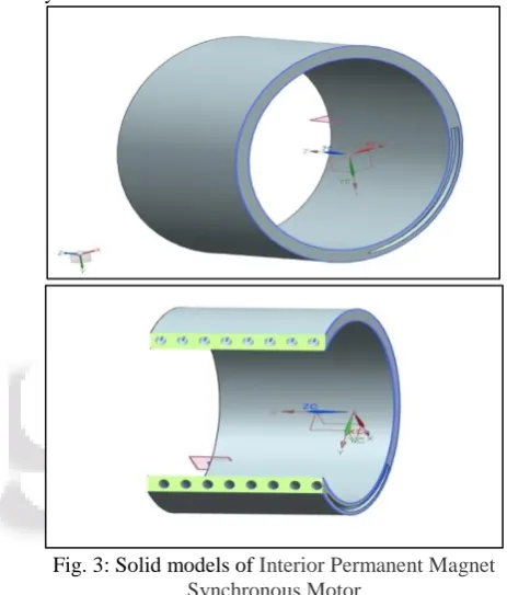
For FE analysis of IPMSM, firstly three-dimensional solid modal of IPMSM is being/created, with the help of unigraphic. Solid modal of IPMSM is designed by using following dimensions – case size is 316 mm (outer diameter) and 280 mm (inner diameter), a pipe diameter is 10 mm is used with no. of turns 8 presents in the solid modal case. Radius of pipe is taken 149 mm with & pitch 20-mm. Dimensions solid modal of IPMSM case is created of IPMSM. Copper material in used to make pipe and cast-iron material in used to make frame of model. Once solid model has been creating the model in export ANSYS for FE analysis.
Fig. 3: Solid models of Interior Permanent Magnet Synchronous Motor
After creating a solid model of IPMSM, finite element analysis is done in ANSYS for FE analysis mesh is generated for IPMSM solid model. The following table 1 shows the various specifications used for analysis of IPMSM Water cooling jacket.
CONTENTS MODEL UNIT
Pipe material Copper -
Frame material Cast iron -
Water cooling jacket 316(outer
dia.)-280(inner dia.) mm
Pipe diameter 10 mm
Flowing fluid inlet
velocity. 0.50 m/s
Water liquid density 998.2 Kg/m2
Inlet water
temperature 300 or 27
K or
0c
Helix pipe height 160 mm
Heat wall temperature 351 or 73 K or 0
c
Wall thickness 24 mm
[image:4.595.303.535.219.491.2]Pipe thickness 2 mm
A. Description of Solid Modal Meshing along with Helix Pipe:
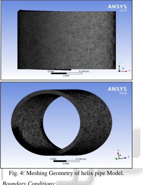
[image:5.595.57.293.175.480.2]The three-dimensional finite element solid model of IPMSM consist of 164692 total numbers of nodes and 858533 numbers of elements while applying tetrahedron meshing techniques. Properties of modal volume 4.1508e-003 m³ of solid model used to create meshing ANSYS. Meshing on solid model is shown in fig 4.
Fig. 4: Meshing Geometry of helix pipe Model.
B. Boundary Conditions:
For a CFD analysis, homogeneous material (copper), IPMSM model is solid and inflexible. A three-dimensional finite element model of IPMSM imported in ANSYS. After applying meshing boundary conditions were applied along with assumptions.
The following assumptions are made to simplify the numerical simulation:
Wall motion is stationary wall
Velocity specific method is magnitude, normal to boundary
Constant gauge pressure
Water liquid [Fluid] inlet 0.50 m/s limit Reference frame is absolute
Shear condition is no slip Connectivity Range
(a) Fluid inlet
(b) Fluid outlet
(c) Heat walls
Fig. 5: all boundary condition applies on model
V. RESULTS
All the results in a flowing fluid, which must be evacuated. Certain materials such as isolating and copper are sensitive to heat. It is thus necessary to transfer this heat towards a cooling system. The three-dimensional solid model of IPMSM generated in ANSYS workbench provide a very fine, good, and fast meshing of geometry representation of IPMSM with accuracy. This result depends on the accuracy of FE analysis solid model of IPMSM with reference to real conditions. This study investigates velocity rising during fluid flow fluent conditions. Results shows that minimum velocity 0.000 m/s and maximum 4.87266 m/s, and Temperature is minimum of the pipe inlet is 299.778 and outlet of the pipe is 339.583 k, and 164692 total number of nodes and 858533 number of elements statistics meshing. From the results it is clear that the water-cooling is also the better solution to cooling the IPMSM.
(a) Temperature inlet
(c) Temperature heat wall
(d) Velocity inlet
(e) Velocity outlet
(f) Temperature graph
(g) Velocity graph
VI. CONCLUSION
A 3-dimensional CFD analysis has been carried out to study of water liquid fluid, velocities variations, and temperature of the fluid flow behavior in a water-cooling jacket of IPMSM solid model. The effect of velocity, temperature of the fluid and walls, pressure of the fluid, thermal conductivity of the fluid, mass flow rate, force of the fluid have been studied 1) The maximum velocity is found that 4.87266 m/s
flowing in the solid model pipe.
2) The maximum temperature of the outlet is 339.583 k, it helps to providing better efficiency for IPMSM.
REFERENCES
[1] Wafter design for totally enclosed electric machines vol.129, 2018,
[2] Design criteria for water cooled systems of induction machines vol.114, 2017
[3] The Equilibrium Design of Radial Magnetic Force for Reduction of Vibration in IPM type BLDC Motor vol.11, pp.2, 2016,
[4] C. B Park, H.W. Lee, B. S. Lee, "Investigation of a thermal analysis method for IPMSM in railway vehicles," Journal of the Korean Society for Railway, Vol.16, No.2, pp. 99-103, 2013.
[5] C. B. Park, "A Study on the Thermal Characteristics of 110kW-class IPMSM for Light Railway Transit using the 3-Dimensional Thermal Equivalent Network considering Heat Source by Iron Loss Density Distributions," The transactions of the Korean Institute of Electrical Engineers, Vol. 62, No. 7, pp. 1038-1044, 2013.
[6] Jung G. C. “A design study on the torque ripple reduction of 210kW-class Interior Permanent Magnet Synchronous Motor for railway vehicles,” The Korean Institute of Electrical Engineers Spring Conference 2013 283 - 284 [7] H.W. Lee, B. S. Lee, "A Study on the Reduction of the Stator Iron Loss on Permanent Magnet Synchronous Motor for light Railway Transit Propulsion System," Journal of the Korean Society for Railway, Vol.15, No.4, pp. 376-380, 2012.
[8] J.H. Choi, S.M. Jang, C. Han, J.H. Ahn, K.H. Sim, "Electromagnetic loss and thermal analysis on high speed PM motor for turbo compressor," KIEE Summer Conference 2012, pp. 618-619, 2012.
[9] Alexander Nollau is with the Institute for Electrical Drives,Universitaet der Bundeswehr Muenchen, 85579, Neub 2011.
[10]Park C. B. , Lee H. W. , Lee B. S. 2011 “Performance evaluation method and examples of the propulsion system for Electric Multiple Unit,” The Journal of the Korean Institute of Power Electronics 16 (3) 42 – 48 [11]http://electricalquestionsguide.blogspot.com/2012/09/ap
plications-synchronous-motors.html
[12]Gyu-Hong Kang, Young-Dae Song, Gyu-Tak Kim and Jin-Hur, “A Novel Cogging Torque Reduction Method for Interior Type Permanent Magnet Motor”, IEEE Transaction on. Industry Applications, vol. 45, No. 1, pp. 161-167, 2009.
[14]G. X. Zhou, R. Y. Tang, D. H. Lee, and J. W. Ahn, “Field circuit coupling optimization design of the main electromagnetic parameters of permanent magnet synchronous motor,” JEET, Vol. 3, No. 1, pp. 88-93, Mar. 2008.
[15]Jang-Ho Seo, Chang-Hwan Im, Sang-Yeop Kwak, Cheol-Gyun Lee, and Hyun-Kyo Jung, “An Improved Particle Swarm Optimization Algorithm Mimicking Territorial Dispute Between Groups for Multimodal Function Optimization Problems,” IEEE Trans. Magn., Vol. 44, No. 6, pp. 1046-1049, Jun. 2008.
[16]Han Y. J. “Temperature characteristics of traction motor in new and existed line,” The Korean Institute of Electrical Engineers Summer Conference 2005 1601 – 1603
[17]Stumberger, G. Stumberger, D. Dolonar, A. Hamler, and M. Trlep, “Evaluation of saturation and crossmagnetization effects in interior permanent-magnet synchronous motor”, IEEE Trans. Ind. Appl., Vol. 39, No. 5, pp. 1264-1271, Oct. 2003.