Design and Implementation of PLC based Elevator
Protection System
Mrs. S. Ramya1, R. Priya 2, S. Rohith 3, S. Senthilnathan 4, A. Shagana5
1, 2, 3, 4, 5
Electrical and Electronics Engineering, Sri Shakthi Institute of Engineering and Technology
Abstract: Elevators have become an essential part of everyday life and it is necessary to provide secure and safe features in it. Automation plays an important role in the development of advanced technology by utilizing hardware and software, also it increases productivity, safety and profitability. The proposed elevator protection system consists of an additional secondary gear motor placed above the crate of the elevator which is automated for emergency conditions under the control of digital system such as Programmable logic controller (PLC) Siemens S7-1200 series. PLC’s are used for their rugged strength to withstand uncertain conditions which occurs in elevators. The signals from PLC controls the secondary gear motor with the help of driver circuits during faulty conditions like power failures, rope damages, primary motor failures. However, if fault occurs in the driver circuits or PLC controllers or secondary gear motor, an exhaust fan is utilized through relay switching for ventilation until rescue arrives. The implementation of the project for modelling and automation system for elevators protection system in real time provides an additional cost of 25% of the whole elevator cost.
Keywords: Arduino, Driver circuit, Elevator, Gear motor, PLC.
I. INTRODUCTION
Elevators and lift have become an essential part of everyday life, particularly for those who work or rise in high class buildings. Elevators area unit vertical raise transportation systems that effectively move folks between floors of buildings. Automatic elevators began to appear as early as the 1930s and the development was hastened by striking elevator operators. There are four different types of elevator. At present the usage is of roped hydraulic residential elevator. It is based around a hydraulic pump that is connected to a piston and pulley. Hydraulic elevators are especially great for home use. Pneumatic vacuums elevator or PVE is the newest innovation in elevator design. PVE’s are revolutionary because they do not require cables, chain, piston or count weights, but instead use the hoist way itself as part of the lifting system. Winding drum and counterweight home elevators use the old style supported a revolving winch and counterweight. Many homeowners install this type of elevators. This elevator is cheaper than hydraulic and pneumatic vacuums elevator. Traction drive elevator systems are seen in the residential space of rare occasion. They are rather more generally seen in business elevator systems. Generally the elevator must be safe and comply with all relevant codes and standards. The elevator is flexible and versatile in operation as possible. The elevator must meet minimum requirements of handling capacity. The advantage of using elevator is to save time and the people will easily move from one place to another place quickly.
1) Problem Description: At present in the elevator, if the elevator cable is loosen up and it would be accelerating downward which cause the passengers to fall down. This is an application of Newton’s second law of force causing the elevator to fall down. When elevator move from one floor to next floor at the time where in case of power failure or any another fault, it may result in suddenly shunt down of elevator to stop there itself. It may cause the people inside the elevator to panic and the oxygen rate decreases rapidly which cause lung disorders if rescued in a limited time or it may be fatal. The main objective of this project is to provide automated elevator protection in uncertain conditions that is to provide a safe and secure feature in modern elevators. To provide a backup system in event of primary emergency system fails to operate during uncertain or emergency conditions. To design the system to be more stable and smooth even during emergency conditions.
II. LITERATURESURVEY
A. Elevator Control System
group control system (EGCS). In order to simulate the important elevator motion and management, do analysis on the management strategy of single elevator and elevator cluster, the paper builds associate elevator cluster management system hardware platform with PLC system of U.S. Rockwell A-B company and four sets 10-story elevator system model among the science lab, writes Associate in Nursing elevator peripheral interface program and a human-machine monitor interface, configures the complete system network, and creates associate elevator cluster system code platform; finally, the paper tests the responsive of the whole system platform through a ladder diagram management program of dispatching strategy of the minimum waiting time.
Anusha A M et al. (2015) analysed the results from their study and recommended that the elevator is an important transport medium in multi-storage building. With the event of higher design technology, buildings are raising in height.
Hence AN elevator becomes a crucial medium of vertical transportation. There are many benefits of AN elevator within the modern times. Hence a lot of importance is given to the planning of AN elevator system, which is easy for the maintenance and to perform an efficient function.
Preliminarily, ancient elevator management systems work on the relay logic. More variety of connections of relay logic are found in ancient elevator system. Balaji V et al., (2015) conducted experiments and concluded that an elevator is one of the important aspects in electronics control module in automotive application. For most individuals residing in urban cities, elevators became Associate in nursing integral a part of their lifestyle. Simply expressed, Associate in nursing elevator may be a hoisting or lowering mechanism, designed to carry passengers or freight, and is equipped with a canard platform that typically moves in fixed guides and serves two or more landings.
Omkar M. Shete et al., (2017) conducted experiments and concluded that with the rising life standards and attention to human and with tremendous development in architectural engineering for multi storage building, the installation of elevators becomes an integral part of the infrastructure for the vertical movement. So, the control system is essential for smooth and safe operation of the elevator. Hence for more efficient performance and maintenance, more importance is given to the design of an elevator control system. In this case one can make the better use of PLC for controlling of elevator which is beneficial due to its flexibility, operational speed, reliability, ease of programming, security, and it is easy in implementing changes and correcting errors. Since output results must be produced in response to input condition within a given period of time, it is an example of a real time system. Ladder diagram programming is selected as it is easy to program the PLC.
B. Design and Control of Three Level Construction Elevator
Yelpokonde Atikesh A et al.,(2016) conducted experiments and concluded that in this paper we are designing and constructing three level elevator control system and increases its steady state and stability by employing a programmable logic controller (Allen Bradley Micrologix -1400 BXBA) the software package used for communication is RSLogix-500/5000 PLC’S area unit helpful in industrial automation wherever variety of equipments area unit replaced by contactor and switches. Elevator is nothing however the vertical transportation device that is employed to transfer the products and peoples limit switch is employed for the ground indication.
The limit switch is used for positioning of floor and the Direct Current (DC) motor is used for movement of elevator cabinet. Electromagnetic relay is employed on top of things circuit to manage elevator in upward and downward direction .As the India is developing country and there wide increase in high rise buildings and malls and elevator is integral a part of infrastructure by implementing such comes we are able to cut back the human efforts, accident due to breakage of rope, efficiency and speed of elevator is improved .Even the time are often consumed by mistreatment such system.
Aditi dutta et al., (2017) conducted experiments and concluded that the rapid population growth at the cities and multi-stored buildings, the need of elevators is being increased. The ladder logic is much flexible so that the serving technique can be changed according to the requirement (like nearest floor-first, floor-having more-people-first etc.).The current floor number will be shown within the lift by a small display.
III.METHODSANDMATERIALS
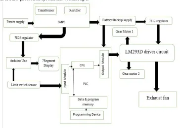
[image:3.612.120.484.152.412.2]1) Block Diagram of Elevator PLC: Power is provided as dc to the motor in case of failure, a sensor such as a relay is used. Emergency power supply and motor is used until normal operating conditions are achieved. In case of failure of the emergency system due to controller failure or driver circuits an exhaust fan operates on the emergency battery this is done when system is at fault condition and supply is switched from motor to fan via a relay or rugged controller with an rotor position sensor is used. A block diagram of PLC protection system showed in Fig.1.
Fig.1 Block Diagram of PLC Protection System
2) Arduino: Arduino UNO is a microcontroller board based on 8-bit ATmega328P microcontroller. Along with ATmega328P, it consists different elements like oscillator, serial communication, transformer, etc. to support the microcontroller. Arduino Uno has fourteen digital input/output pins (out of that half dozen are often used as PWM outputs), half dozen analog input pins, a USB association, an influence barrel jack, an ICSP header and a reset button. Fig.2 shows the arduino UNO.
[image:3.612.162.449.516.712.2]3) Programmable Logic Controller: The S7-1200 CPUs with Safety Integrated handle both standard and safety-related tasks. A compact design with integrated IO, communication interfaces that meet the highest industry requirements and a range of powerful integrated technological functions make this controller an integral part of a comprehensive automation solution. 4) CADD Model: Model of a regular elevator along with the modified version of a differential attached at the top of lift box
connected to a gear at either side in a gear rack to provide support of emergency and stability as per design. Model is designed in solid works as a working model for suitable gear systems. Supportable weight is calculated theoretically. According to the motor rating. CADD model of elevator showed in Fig.3.
Fig.3 CADD Model
5) Power Supply: A 230v ac is stepped down using a stepdown transformer of 24v and rectified to dc for controller supply, dc voltage is further regulated to 12v using a IC7812 voltage regulator connected in series and 5v using IC7805 voltage regulator, the 12v and 5v are supplied to varies compounds such as exhaust fan, microcontroller, driver, motor etc. Thus power conversation to PLC controller is done by a SMPS which is a transformer coupled to a rectifier. Using a relay output of 24v from the PLC is switched to required supplies as per the design shown in Fig.4 Power supply of elevator.
Fig.4 Power Supply of Elevator
IV.SIMULATIONRESULT
A. Simulation
The software TIA portal v11 is used for simulation of Siemens PLC controller, where the result before applying to the hardware setup are simulated and verified. One of the primary advantages of simulators is that they are able to provide users with practical feedback in the designing real-time systems. This allows the programmers to identify, verify and correct the errors which reduces the error while execution of the system in a practical way.
Fig.5 Simulation Input
Perfect control is done using simulation and expected result are exactly using normally closed and normally opened contacts. Monitoring of simulation is done using TIAPORTALV11 software (Totally Integrated Automation). Time management and power consumptions cannot be calculated but perfect control of motoring operation forward, reverse, ON and OFF and other controls can be done easily. If the controller is implemented once it can be used again and again. Program can be used in a simple manner too, totally 366 input and output are used. Fig.5 explains the simulation input and Fig.6 shows the simulation output of ladder diagram.
Fig.5 Simulation Output of Ladder logic
B. Arduino Simulation
Arduino simulation is done through porteus software, where the floor at which the elevator acts is sensed. By using elevator sensor as input to the Arduino, and is simulated. Embedded controller is necessary for controlling of sensitive controllers. Arduino hardware exactly is same as that of Proteus simulation. But practically high voltage input of the elevator is switched to a withstandable voltage by using a suitable relay operation as such the Arduino is heated. Thus it is necessary maintain a cooler controlled environment for using embedded controller.Fig.6 shows the output of arduino porteus.
V. HARDWARERESULT
A. Hardware
Perfect control of motoring, forward as well as reverse directions. During emergency control of motor, sensor of high accuracy can be detected but power losses will be more. A chance of real time heat losses can be observed in hardware. Driver circuit in which exhaust fan is connected to it. In driver circuit externally we use exhaust fan which receives supply from the battery. The overall cost of extra battery increases the total performance of the elevator. In PLC, totally 366 input and outputs are used in a single controller easily. For extra monitoring SCADA HMI can be used. Manually if the push button fails to work, in case of emergency we can operate the controller manually. Fig. 7 shows the PLC hardware and Fig. 8 shows the output of hardware results.
Fig.7 PLC Hardware
Fig, 8 Hardware circuit set up
B. Working Condition of Hardware
In this system power supply of 230v is given to the step-down transformer which is converted to a 24v alternative current then processed to a rectifier where the alternative current is converted to direct current supply which is given to the PLC. Further the supply is regulated to 12v using 7218 voltage regulator IC that is supplied to the driver circuit, exhaust fan to operate and is again regulated to 5v using 7805 voltage regulator to supply the arduino and relays used. Fig.9 shows the hardware of elevator.
SIMENS S7-1200 SERIES DC/DC/relay
Exhaust Fan Audino-Floor-Display Controller
Driver & Voltage regulator circuit
Fig.9 Interfacing of elevator with siemens PLC
Normal working condition of an elevator is such that if the respected floor is selected, the output from the switches is given to the PLC as an input. Where it is processed and the output is given to the driver circuit enable pins and the motor is operated by the as per the requirements. When the respected floor is sensed by the limit switch it sends an input to the plc which gives a command to stop the motor and also sends an input to the arduino to display the respected floor .in case if an emergency occurs such as failure of primary motor or power failures relay switching occurs or an feedback output is given to plc as an input which in turn operates the emergency secondary motor that operates automatically. In case of failure of controller or the driver ventilation is provided for the passengers of the elevator.
VI.CONCLUSION
The heart of the elevator protection system is the secondary gear motor which operates in emergency/faulty conditions like power failure, rope damages, and primary motor failure is achieved. The elevator protection system is fully automated to provide stable operations during emergency conditions that risks human life. The mechanical braking can be done through the differential systems which consists if a gear rack that provides more stable and smooth operation during working of an elevator. Since the PLC are rugged and through testing it withstand the faulty conditions where the operation of the PLC controller remains unaffected. Immediate operation is done through the PLC controller during uncertain conditions. The relay operation play a important role in protecting the system by tripping during transient conditions and switching operation is also done to meet the requirement of the elevator emergency protection system.
REFERENCES
[1] Adhikusmantoro and Agus Nuwolo,(2017),”Freight elevators controlling four floors with Zelio PLC SR3B261FU and VSD ATV71 lift for saving energy universities PGRI semarang”, International journal of research in advanced engineering and technology, Volume 3, Issue 4.
[2] Aditi Dutta, Kajal and Rasmita Gouda, (2017), “ Elevator operation control through PLC”, An international journal of engineering and technology, Volume 4, Issue 4
[3] Ameem Ahmed Khan, Hiren Patel, Derrell Dsouza and Swapnil Desai,(2019),”Implementation of elevator control system based on PLC”, International journal of recent trends in engineering and research, Volume 3, Issue 9
[4] Anusha A M and Ashok V. Sutagundar, (2015), “Design of a PLC Based Elevator Control System”, International Journal on Emerging Technologies (Special Issue on NCRIET). Volume 6, Issue 2.
[5] Balaji V and Sudhakar G,(2015), “ Design and analysis of elevator control system using PLC”, International journal of digital electronics, Volume 1, Issue 2. [6] Kamalu U A and Ogunleke F A,(2018), “ Implementation of a four floor PLC elevator system”, International journal of scientific and engineering research,
Volume 9, Issue 6.
[7] Omkar M.Shete, Amrita A.Vitekar and Ashwini N.Patil ,(2017) “Design and control of an elevator control system using PLC”, International journal of innovation research in electrical, electronics, instrumentation and control engineering. Volume 5, Issue 4.
[8] Maruthaipandian G, Ramkumar S and Muruganandam M,(2015), “Design amd implementation of BLDC motor using regenerative braking for electric vehicle”, International journal of advanced research in electrical, electronics and instrumentation engineering. Volume 4, Issue 2.
[9] Sandar Htay, Su Su Yi Mon,(2015),”Implementation Of PLC Based Elevator Control System”, International Journal of Electronics and Computer Science Engineering - ISSN - 2277 – 1956.
[10] Xinyun Yu Xiaoyun Feng and Chenglin Xiong,(2009),”Design and implementation of elevator group control system research platform”, International workshop on information security and application.
[11] Yelpokonde Atikesh A,Dabhadevaibhav G and Anap M V,(2016),”Elevator Control System By Using PLC”, IJ ARIIE - ISSN(O) - 2395 - 4396 Volume 2, Issue 3.
Siemens PLC – interface-to circuits