System Design Temperature and Humidity Control Room
with Android
Sukandar Sawidin
Information Technology Dept Manado State Polytechnic North Sulawesi - Indonesia
Deitje S. Pongoh
Electrical Engineering Dept Manado State Polytechnic North Sulawesi - Indonesia
Ali A. S. Ramschie
Electronic Technology Dept Manado State Polytechnic North Sulawesi - Indonesia
ABSTRACT
Human need for technology is difficult dammed because there are many facilities that enable people to be able to optimize performance at work every time.
Currently mobile handheld electronic devices no longer only have the functionality of the phone or sms but improved to be a medium that can control every electronic device in the house.
This study aims to control the temperature and humidity in a room using arduino uno microcontroller that is controlled with android smartphone with wifi media.
Test results show that applications on Android smartphones can inform the state of temperature and humidity in a room. Control Room App on Android with Auto, Semi Auto (Cold, Hot and Hot) and Manual (Fans and Heaters) option.
Remote control distance on the Android app to Arduino Uno microcontroller is approximately 150 meters, The duration of delay that occurs when Arduino Uno processes the command from Android at 0-80 meters distance is 0.5 - 1 second and at a distance of 90-150 meters is 2-3 seconds.
General Terms
Android Smartphone, Eclipse IDE (Integrated Development Environment)
Keywords
Arduino Uno, Wifi, Sensor DHT11
1.
INTRODUCTION
Human need for technology is increasing as more facilities facilitate human being to be able to optimize performance at work every time. [1,2]
Currently mobile handheld electronic devices no longer only have phone or sms functions but improved to be a medium that can control every electronic device in the house, where one of its functions can regulate the temperature and humidity in the room. [1,2]
Smartphones as part of the ever evolving mobile technology is a phone that has many features, such as transmitting data over a wireless connection remotely. One is by using Wifi technology. [2,3]
It will be designed Android-based smart room control for controlling the temperature and humidity of the room, through a smartphone. Where smartphone as a new alternative solution for remote control. [2,5]
This study aims to create a system of temperature control and humidity of the room using a combined circuit between the microcontroller and the relay for ON / OFF Fan or Heat
power equipment connected via smartphone with Wifi connection. [4]
2.
LITERATURE REVIEW
2.1
Android
Android is an operating system for Linux-based mobile devices that includes operating systems, middleware and applications. Android provides an open platform for developers to create the desired application.
Android is a new generation of mobile platforms, a platform that gives developers the ability to develop as they see fit. The underlying Android operating system is licensed under GNU, General Public License Version 2 (GPLv2) [6.7]
2.2
Arduino Uno Mikrokontroler
Arduino Uno microcontroller is an electronic circuit that is open source, and has hardware and software that is easy to use. Arduino can recognize its surroundings through various types of sensors and can control lights, motors, and various other actuator types. Arduino has many types, including Arduino Mikro, Arduino Uno, Arduino Mega 2560, Arduino Fio, and others. (www.arduino.cc) [1,3]
2.3
Board Ethernet Shield W5100
Board Ethernet Shield is a module that works to connect Arduino board with internet network, by pairing the module above Arduino board then connect with RJ45 network cable and Arduino ready to be controlled via internet.
In the arduino ethernet itself there is a micro SD slot that serves as a file storage. Ethernet shield W5100 and SD Card using SPI bus (via ICSP) to be able to communicate with arduino uno microcontroller. SPI (serial peripheral interface) are digital pins 10, 11, 12 and 13 on arduino uno. [1,2]
2.4
Wireless Fidelity (Wi-Fi)
2.5
Temperature and Humidity Sensors
(DHT11)
[image:2.595.114.234.193.312.2]DHT11 is a composite sensor containing digital signal output calibrated from temperature and humidity. The application of digital module collection technology dedicated temperature and humidity sensing technology, the product has high reliability and excellent long-term stability. sensors include resistive wet components and NTC temperature measurement devices (negative temperature coefficient) and connected to high performance 8-bit microcontrollers.
Figure 1. Sensor DHT11
In figure 1. The DHT11 sensor is a digital sensor that can produce relative humidity and temperature readings in a system in an electronic circuit.
DHT11 calculates relative humidity by measuring the electrical resistance between two electrodes. The humidity
sensing component of DHT11 is the substrate moisture holding (usually a salt or a conductive plastic polymer) with the electrodes applied to the surface. When water vapor is absorbed by the substrate, the ions are released by the substrate which increases the conductivity between the electrodes. The change of resistance between two electrodes is proportional to the relative humidity. High relative humidity reduces the resistance between the electrodes while the relatively low humidity increases the resistance between the electrodes. [2]
3.
METHODOLOGY
In this study using the design method that begins by creating a prototype smart room and design of smart room control system to regulate the temperature and humidity of air in the room with android smartphone as a controller or remote and use Wifi as a communication medium. Then perform system testing and evaluation of hardware and software.
4.
RESULT AND DISCUSSION
4.1
Block Chart Room Control System
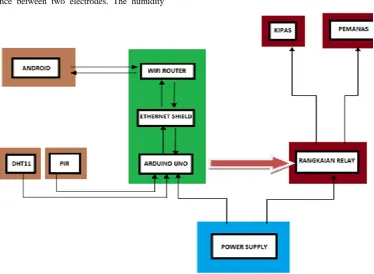
In Figure 2. The workings of System Block diagram as follows:
When the Android app is activated it will connect with Wifi Router then input IP address, if appropriate Android
Application ready to give command
Fig 2: Blok Diagram the Room Control System
Description of System Block Diagram: In the insert block (light brown color) consisting of android device and application, the command execution for media output is done through the android device where the application will convert the GUI understood by the user into the program form to the I/O command on arduino uno before the message gets to arduino uno must go through wifi router to Ethernet shield. Arduino Uno will give command to enable output through
relay circuit as needed output. The DHT11 sensor and PIR sensor are inputs that will provide information to the arduino and forwarded to the android device.
4.2
Design Circuit Room Control System
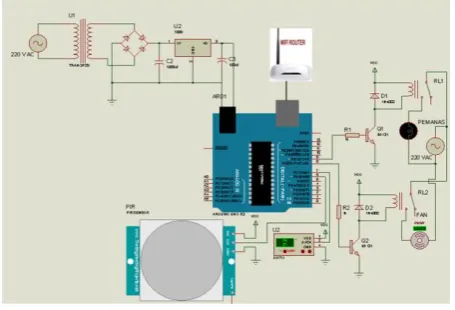
[image:2.595.115.490.371.645.2]There are routers and Ethernet shield that process the system, command or packet information sent from android device will be processed to be able to enter on microcontroller.
In Figure 3 shows a series of Room Control Systems design. When the signal from android smartphone received wifi module then Arduino Uno microcontroller will process in accordance with the input given so that the desired output is met.
[image:3.595.325.544.79.718.2]Suppose an option on the android app for manual control by pressing the Fan button to enable Fan indoors via Relay RL2 or Heaters to heat the room via Relay RL1. Android Smartphone as a controller or remote and use Wifi as a communication medium.
Fig 3: Design Circuit Room Control System
[image:3.595.55.283.221.376.2]4.3
Flow Chart Designing Room Control
System
Fig 4: Arduino Uno Flowchart System
Explanation of the picture 4. flowchart arduino uno: 1. Start.
2. Initialization, in this section the process is done to recognize arduino IP, MAC Address, DHT Sensor and PIR Sensor as a giver of information on arduino and pins used.
3. Start Connectivity, if it is recognized by Ethernet shield arduino can start connection between arduino, Ethernet shield and android device. 4. Preparing to Receive Datagram, the arduino
prepares to receive the datagram sent from each input.
5. Ethernet Receiving Data, In this section Ethernet receives every packet of data transmitted.
6. Data Processed, any data that has been entered from each input is processed where arduino will read every packet sent whether in accordance with the program.
7. Data Recognized, from this process arduino will do the decision where in this decision arduino can recognize every packet already programmed, if not recognized arduino will return to get ready to receive datagram.
8. Data Executed, any data that has been recognized will be executed by arduino.
9. Send Feedback, in this section after executed arduino will send a feedback to the android application that has been made.
10. Finish.
[image:3.595.76.270.418.700.2]Explanation of the picture 5. Flowchart android: 1. Start
2. Set IP, In android to be able to enter the application must enter IP (option → Set IP), IP to be entered the IP Arduino.
3. Conect, If you have entered the IP with the corresponding process will continue to the main view, otherwise it will return to the IP Set view. 4. Main Activity.
5. Receiving Data and Displaying Data.
6. There is Button 1 pressed, Button 2 is pressed (Cold, Warm, Hot) and Button 3 is pressed (ON / OFF Fan and heater), otherwise pushes back button to receive data and displays data.
7. Submitting Data packets.
8. Success, in this process if the successful data packet data sent from arduino will be forwarded on the display but if the message error message is not executed (discarded).
9. Displays, successfully executed messages will be given feedback from arduino to android.
10. Out, in this part of the process where if this exit the application will be didestroy but if not the application will return to the main view.
11. Finish.
[image:4.595.316.528.101.405.2]4.4
Design Application Display Structure
Fig 6: Application Display Structure
Explanation of Figure 6: 1. Main
In the user application main view is given 3 interface options
2. Option
Option is the menu that contains the IP Set section. In the Set IP options section the user must enter the IP address of the Ethernet Shield that we use as the communication medium with the arduino.
3. 6 Full Keys
In this menu there are 6 buttons where, 1 button for auto, 3 buttons for semi auto and 2 buttons for manual.
4. Exit
The exit menu works to exit the app and will not disconnect between apps and arduino..
4.5
Designing Appviews
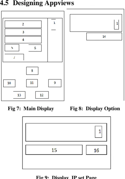
Fig 7: Main Display Fig 8: Display Option
Fig 9: Display IP set Page
In Figure 7. is the Application's Main Display, then Figure 8. is a display of options that will contain IP settings.
In Figure 9. is the design of the display settings, in the display of this setting where IP input in order to run the Application will be made.
The description of the images (7, 8 and 9) corresponds to the above view:
1. Option Menu 2. Temperature View 3. Display Moisture 4. Selected mode (Button) 5. Textview Cooler (on / off) 6. Textview Heater (on / off) 7. Room Status
8. . Auto Button 9. Cold Button 10. Ordinary Button 11. Hot Button 12. . Cooler Button 13. Heater Button 14. IP Set Menu
4.6
Android App Creation
Making this Application begins by creating an Interface or GUI view in accordance with the schematic that has been designed (images 7,8 and 9).
[image:5.595.325.532.69.308.2]In making the application on this system using java programming tools that is Eclipse IDE. Application creation begins with the GUI interface or display as shown in Figures 10 and 11
Fig 10: Main Activity Interface
Fig 11: Activity Interface Setting Option
Fig 12: Design On the Room Control Program
In figure 12. For smart room program designed on arduino uno microcontroller is made by using Arduino IDE programming tools. The function of the Arduino program to initialize the input and output pins, which will be sent by the android device by converting the datagram sent into logical commands "LOW" and "HIGH" to enable and disable the system created on each component and initialize the IP address into destination address of datagram submission of android device.
5.
TESTING SYSTEM
5.1
Android Application Testing and
Arduino Program
Testing is done to test the work of the Android app and Arduino program in sending and receiving Data. Testing is done to find out whether the datagram sent from Android successfully received and processed by Arduino. The test is performed using the Serial Monitor function on the Arduino IDE to see if the value of the datagram sent from Android matches the Feedback returned to Android.
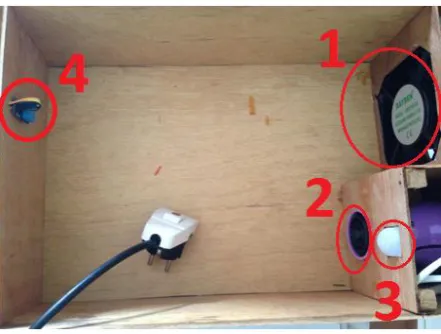
[image:5.595.65.270.174.629.2]Smartroom control system testing is done by making electronic equipment to be controlled with android smartphone (Figure 13).
[image:5.595.320.541.572.739.2]In figure 13. is a prototype of smart room control system consisting of 1. Fan / cooler, 2. Heater, 3. Motion Sensor (PIR) and 4. Temperature and Humidity Sensor (DHT11). The fan is used to cool the room and the heater can warm the room when the room is cold. The DHT11 sensor will provide information to the temperature and humidity arduino indoors and the PIR sensor provides information to the Arduino if there is movement within the chamber.
Before testing the application first connect from the Android Device with the media Router.
Fig 14: Wifi Selection
[image:6.595.364.493.69.250.2]After Android is connected with Wifi Router, in this test using Wifi Router with SSID 'KANDAR- PC_Network_Arduino', after that user can to application to input IP address via Android to Ethernet Shield IP address (192.168.1.11) as in figure 15.
Fig 15: Setting IP Ethernet Shield
After the IP input is completed and saved then the user can use the control room android application created.
5.2
Testing Room Control App
Prior to testing performed on the Arduino program it was assumed that cold and non-cold temperatures were limited to a temperature value of <= 290 C cold temperatures. If the temperature value is> 290 C, the temperature is not cold. For warm and not warm temperatures limited by temperature value> = 300 C warm temperature. If the temperature value is <= 290 C, the temperature is not warm.
For hot and not hot temperatures are limited by If temperature value> = 320 C hot temperature. If the temperature value is <=
290 C, the temperature is not hot.
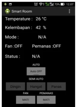
In figure 16. When smart room application on android is activated visible sensor DHT11 display Temperature: 260 C and humidity: 42% on prototype room.
Fig 16: Room Control App View
1.
Mode Auto
[image:6.595.375.494.349.522.2]Trial of Auto Arduino Mode will work on its own according to the program by obtaining input from both sensors. After pressing the toggel button Auto can be seen the humidity and temperature in the room contained on the display, later the temperature and humidity can change according to the state of the room read the sensor (Figure 17).
Fig 17: Automatical ON Display
If there is movement in the room the active pear sensor and indicator LED 3 are lit, otherwise there is no blowing 3 turns. If the temperature is monitored > 290 C then the fan will work (ON) cool the room, otherwise if the temperature is monitored < 290 C then the heater will work (ON) to heat the room. If temperature = 290 C fan off heater off
2.
Control Semi Auto
[image:6.595.79.259.401.478.2]Fig 18: Semi Auto View (Cold Mode)
If temperature> 290 C then mode: cold, Fan: ON, heater: OFF and Cool status.
[image:7.595.358.498.88.270.2]If the temperature is <290 C mode: cold, Fan: OFF, heater: OFF and status It's cold. As in Figure 19.
Fig 19: Auto Semi Display (Status Already Cold)
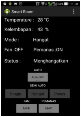
In figure 20, when the temperature is <290 C then mode: warm, Fan: OFF, heater: ON and Warming status.
Fig 20: Semi Auto Display (Warm Mode)
[image:7.595.102.235.322.509.2]In figure 21. If temperature> = 300 C mode: warm, Fan: OFF, heater: OFF and status Warm.
Fig 21: Semi Auto View (Status is Warm)
The temperature shown is 300 C with a moisture of 43%, can
be seen from the Mode on the warm display and the Status contains feedback from the arduino displaying the already warm display as the arduino uno informs the temperature in the room 300 C.
In Figure 22. If the temperature is <= 300C then mode: heat, Fan: OFF and Heater: ON as well as the Heat state. The status contains feedback from the arduino showing the display heats so that the heater is ON.
Fig 22: Auto Semi Display (Heat Mode)
[image:7.595.365.494.392.575.2] [image:7.595.100.235.554.748.2]Fig 23: Semi Auto View (Status Already Heat)
[image:8.595.363.494.115.278.2]3.
Manual Mode
Figure 24. Manual mode using 2 Keys (Fan button and Heater button) After pressing Fan button, on Fan: ON and Heat display: OFF and also feedback from arduino Mode : Manual.
Fig 24: Manual Mode Display (Fan Active)
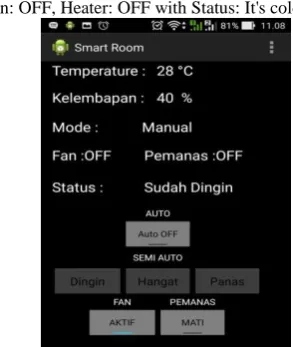
In figure 25. Manual Mode Temperature: 280 C and Humidity: 40%, Fan: OFF, Heater: OFF with Status: It's cold.
Fig 25: Manual Mode Display (Status Already Cold)
In Figure 26. After pressing the Heater button then on Fan : OFF and Heater: ON, there is also feedback from arduino containing Mode: Manual.
Fig 26: Manual Mode Display (Heater ON)
Display Temperature: 280 C and Humidity: 40%, Fan: OFF,
[image:8.595.364.491.316.510.2]Heater: OFF with Status: It's Cold.
Fig 27: Manual Mode View (heating state)
In figure 27. Manual mode display Temperature: 310 C and Humidity: 40%, Fan: OFF, Heater: ON with Status: Heating.
6.
ANALYSIS OF TEST RESULTS
6.1
Tests Distance Control Tool With
Android
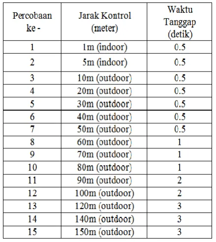
[image:8.595.103.231.341.510.2] [image:8.595.84.231.543.717.2]Table 1. Tests Distance Control Tool with Android
From the tests performed can be seen the performance of Arduino Uno in receiving orders and send feedback to Android. The time required by arduino to execute received commands ranges from 0.5 to 3 seconds. The response speed of the Arduino is influenced by the distance as well as the obstruction and signal strength of the Wifi Router used, the better the quality of the Wifi Router the more distant the connection is to send the delivery to Arduino Uno.
6.2
Analysis the Room Control System
Application and simulation requirements for the room control system performed are as follows:
1. Needs an application, 1 fruit Android-based smartphone.
2. Room control requirements: Arduino Uno Microcontroller, Ethernet Shield, Power Supply, DHT11 Sensor, Motion Sensor (PIR), Fan, Heater, 2 Relay Driver and Led Indicator 3 pieces.
3. Wifi Router, 1 piece to receive string signal from Android.
Applications in pairs on Android-based smartphone in this study using Asus Version Andorid 5.0. The created app can communicate with the smarthome control using a Wifi connection.
Application control room with android will send data via Wifi
which then executed by Arduino Uno microcontroller. Microcontroller sends a signal to be able to control the room.
7.
CONCLUSION
From the results of the tests conducted, it can be concluded that the system controls the temperature and humidity of the room with android using Arduino Uno Microcontroller can control the temperature and humidity in the room through the interface on the android smartphone screen and the distance of the android smartphone with Wifi Router can control the electronic equipment (Fan and Heaters) with a distance of 150 meters. Response time when the android button is pressed for a distance of 1-50 meters 0.5 seconds and for a distance of 60-150 meters 1-3 seconds.
8.
THANK-YOU NOTE
The authors would like to thank RISTEK DIKTI, IJCA, P3M Manado State Polytechnic and all those who can not be mentioned one by one so that this research can be done.
9.
REFERENCES
[1] Abdul Kadir, A Practical Guide to Studying Microcontroller Applications and Its Programming Using Arduino, Andi Yogyakarta, 2013.
[2] Istiyanto Eko Jazi, Introduction to Electronics and Instrumentation Approach Project Arduino and Android, CV ANDI OFFSET, Yogyakarta, 2014
[3] Heri Andrianto, Aan Darmawan, Arduino Learn Fast and Programming, Informatics Bandung, 2016.
[4] R.A.Ramlee, M.H.Leong, R.S.S. Singh, M.M.Ismail, M.A.Othman,H.A.Sulaiman, M.H.Misran, M.A.Meor Said, Bluetooth Remote Home Automation System Using Android Application, The International Journal of Engineering And Science (IJES), Issue 01, Volume 2, pp.149-153, 2013.
[5] Safaat, Nazarudin, Android Mobile Application Programming Smartphone and Tablet PC Based Android, Jakarta: Informatics, 2011
[6] Steven F. Barrett, Atmel AVR Microcontroller Programming And Interfacing, First Edition, Colorado (USA) : Morgan and Claypool Publishers, 2007. [7] Sukandar Sawidin, Sulastri Eksan, Ali A.S. Ramschie,