ISSN (Print) : 2320 – 3765
ISSN (Online): 2278 – 8875
I
nternational
J
ournal of
A
dvanced
R
esearch in
E
lectrical,
E
lectronics and
I
nstrumentation
E
ngineering
(A High Impact Factor, Monthly, Peer Reviewed Journal)
Website: www.ijareeie.com
Vol. 8, Issue 3, March 2019
Reactive Power Management in Distribution
System using UPFC
Honey Baby1, J. Jayakumar2
Research Scholar, Dept. of EEE, Karunya Institute of Technology and Sciences, Coimbatore, Tamilnadu, India1 Professor, Dept. of EEE, Karunya Institute of Technology and Sciences, Coimbatore, Tamilnadu, India2
ABSTRACT:In the present era, the quality of the power system should be more specific when it reaches customer ends. Key industrial loads need reactive power for nutritious magnetic field, for example, transformers, furnaces, induction motors etc. Reactive Power Compensation (RPC), a chief power quality issue in the distribution system, which affects the performance of the power system. The core fact behind reactive power compensation is the amplified system stability, better utilization of gadgets connected to the systems voltage regulation,dropping system losses associated with the system. The complete pillar of the compensating strategies and power electronic application in compensating devices is depicted in this paper. FACTS devices are energetic reactive power compensator capable of contributing reactive power to the grid and consuming reactive power from the grid. This paper proposes the UPFC, a FACTS device for the renumeration of reactive power. The compensation using the UPFC modeling is also discussed in this work. The UPFC normally mounted between source voltage and critical or sensitive load. The configuration of UPFC has been scheduled for improving voltage profile management and power factor performance for different sorts of loads in distribution system. UPFC is an effective degree to sustain voltage stability and improve power quality events of distribution system. The simulation is performed in MATLAB for UPFC and voltage source converter (VSC).
KEYWORDS: Reactive Power Management, UPFC, Distribution System, Power Quality, Power Factor, Voltage Stability.
I.INTRODUCTION
In power system, stability is one of the imperative features for consistent power supply. The reactive power compensation can be accomplished by using Flexible AC Transmission Systems devices (FACTS), which offers virtuous flexibility to control the active and reactive power flow and bus voltages in the power system.In India, there are still several villages or isolated areas which are not electrically coupled but to empower those deserted or isolated areas, the apt keys are microgrids.These microgrids can deliver continuous and lucrative electric power to such areas. For such microgrids, the hybrid grouping of non-conventional and conventional energy sources are sensible solutions because it crops cost-effective and eco-friendly power. But power quality is the vital tackle in such type of microgrids and an archetypal disadvantage is the voltage profile [1].
ISSN (Print) : 2320 – 3765
ISSN (Online): 2278 – 8875
I
nternational
J
ournal of
A
dvanced
R
esearch in
E
lectrical,
E
lectronics and
I
nstrumentation
E
ngineering
(A High Impact Factor, Monthly, Peer Reviewed Journal)
Website: www.ijareeie.com
Vol. 8, Issue 3, March 2019
In this paper, following sections designate a brief discussion of the matter and a simulation model that attests the event of voltage stability due to unbalanced loads are presented. An authoritative reactive power compensation approach has been implemented to fix it.
II.UNIFIED POWER FLOW CONTROLLER
The UPFC is a device which can regulate simultaneously all three parameters of line power flow (line impedance, phase angle and voltage).It is a one of the FACTS family that used to optimum power flow in transmission. A Unified Power Flow Controller (UPFC)provides fast acting reactive power compensation on high voltage electricity transmission networks.The UPFC is a combination of static synchronous compensator (STATCOM) and static synchronous compensator (SSSC).The key factor for the wide spreads of UPFC are its ability to power flow bidirectional maintaining well-delimited DC voltage, workability in the wide range of effective conditions.
Apparently,the UPFC could be supporting Instantaneous governor of all essential power system parameters i.e. transmission voltage, phase angle and impedance. The controller can be rewarding functions of reactive series compensation, shunt compensation, and phase shifting meeting multiple control objects. From a practical perspective, the purposes are met by applying a boosting transformer inoculated voltage also an exciting transformer reactive current. The inoculated voltage is interleaved done by a series transformer [4]. In addition to this, transformers, the general edifice of Unified Power Flow Controller (UPFC) encompasses besides a "back to back" AC to DC voltage source converters functioned from a shared DC Link capacitor.
The UPFC is lately introduced FACTS controller, it is having the competence to control all the distribution parameters. UPFC achieves the functions of diverse FACTS devices like SVC, TCSC, STATCOM, D-STATCOM and the phase angle regulator and it also offers additional flexibility by merging some of the functions of these controllers. It enhances voltage stability and active and reactive power flow in distribution system [6]. Thus, sheltered loading can be done, hence it also rises and alleviates the stability in the power systems. UPFC entails of two voltage-sourced converters (VSCs) which are coupled to each other with a common dc link. Its series converter enclosures controllable magnitude and controllable phase angle of ac voltage in series with our distribution system [7].
Fig.1 Basic Structure of UPFC
ISSN (Print) : 2320 – 3765
ISSN (Online): 2278 – 8875
I
nternational
J
ournal of
A
dvanced
R
esearch in
E
lectrical,
E
lectronics and
I
nstrumentation
E
ngineering
(A High Impact Factor, Monthly, Peer Reviewed Journal)
Website: www.ijareeie.com
Vol. 8, Issue 3, March 2019
Fig. 2 Power exchange of the Shunt Converter
Fig. 2 explains the Power exchange of the Shunt Converter.Fig.2 shows the transfer of the reactive power between the
UPFC and the electrical system. The shunt converter produces a voltage in phase with VA but with variable magnitude. If = . The UPFC injects some reactive power, if = the UPFC fascinates some reactive power and no reactive power is transferred for Vs=VA [9].
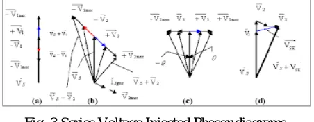
Fig. 3 Series Voltage Injected Phasor diagrams.
As demonstrate in figure 3, by the appropriate control of phasor , the three regular power flow control functions: 1) Voltage regulation
2) Phase Shift.
3) Series reactive compensation.
Simultaneous control of terminal voltage, line impedance and phase angle consent the UPFC to accomplish multifunctional power flow control.
III.MATHEMATICAL MODELLING OF UPFC
A. MODELING OF SERIES CONVERTER
To advance the series converter model, Kirchhoff’s voltage equations (KVL) for the phase ‘a’ of the series branch can be written as
+ = − + (1)
Likewise, the KVL equations can be written for phases ‘b’ and ‘c’. The KVL equations for three phases in matrix form can be written as follows.
=
⎣ ⎢ ⎢ ⎢
⎡ 0 0
0 0
0 0 ⎦⎥
⎥ ⎥ ⎤
+
− +
− +
− + (2)
ISSN (Print) : 2320 – 3765
ISSN (Online): 2278 – 8875
I
nternational
J
ournal of
A
dvanced
R
esearch in
E
lectrical,
E
lectronics and
I
nstrumentation
E
ngineering
(A High Impact Factor, Monthly, Peer Reviewed Journal)
Website: www.ijareeie.com
Vol. 8, Issue 3, March 2019
= + + ( − ) (3)
B. MODELING OF SHUNT CONVERTER
Scheduled in a similar way, the differential equations for the shunt converter currents are given by
= − + − (4)
= − + − (5)
C. MODELING OF DC LINK CAPACITOR VOLTAGE
In general, the triumph of UPFC rest on the stability of the dc link voltage among the series and shunt converters. Even though, during active conditions, the input power to the shunt converter should be equal to the sum of series injected power and the rate of change of stored energy in the capacitor on an instantaneous basis. Consequently, by power balance we obtain the equation below [10].
= − − − − = + (6)
= − − − − − (7)
Henceforth above equation (7) and (8) directs the dc-link capacitor voltage of UPFC.
IV.SIMULATION AND RESULTS
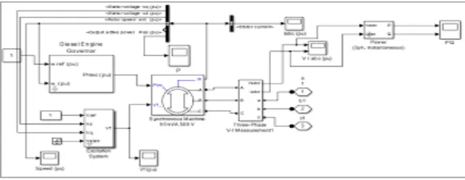
The analysis is done on single phase basis. The simple power system encompasses of a single-phase voltage source, transmission line and an impedance load.The real and the reactive power flow are attained from the simulation with and without compensation.The Simulink archetypal for the uncompensated system is shown in Fig. 4. Moreover, Fig.5 to 10 depicts the simulation results [11,12].
ISSN (Print) : 2320 – 3765
ISSN (Online): 2278 – 8875
I
nternational
J
ournal of
A
dvanced
R
esearch in
E
lectrical,
E
lectronics and
I
nstrumentation
E
ngineering
(A High Impact Factor, Monthly, Peer Reviewed Journal)
Website: www.ijareeie.com
Vol. 8, Issue 3, March 2019
Fig. 5 Active and Reactive Power without UPFC
Fig. 6 Active and Reactive Power With UPFC
In general, Fig.5 and Fig. 6 shows the active and reactive power flow. To clarify, without UPFC the real and reactive power varies slowly with harmonics. After addition of UPFC it become harmonic free and also et more precise real and reactive power.
ISSN (Print) : 2320 – 3765
ISSN (Online): 2278 – 8875
I
nternational
J
ournal of
A
dvanced
R
esearch in
E
lectrical,
E
lectronics and
I
nstrumentation
E
ngineering
(A High Impact Factor, Monthly, Peer Reviewed Journal)
Website: www.ijareeie.com
Vol. 8, Issue 3, March 2019
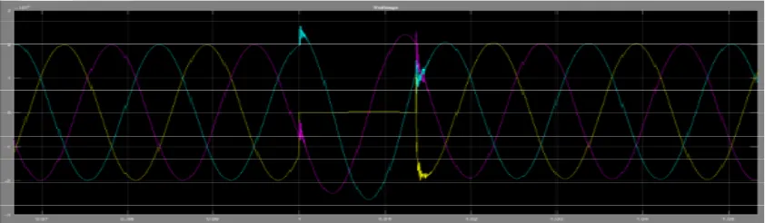
Fig. 8 Grid Voltage With UPFC
To enumerate, both Fig.7 and 8 illustrates the grid voltage through fault condition without andwith UPFC
.
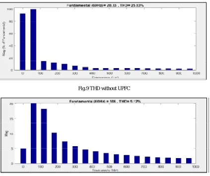
In fact, the grid voltagewithout using UPFC is 25.84% and with UPFC it compacts to 5.13%. Subsequently by adding UPFC the grid voltage become more accurate than without UPFC. The output become sine wave without any disturbances.Fig.9 THD without UPFC
ISSN (Print) : 2320 – 3765
ISSN (Online): 2278 – 8875
I
nternational
J
ournal of
A
dvanced
R
esearch in
E
lectrical,
E
lectronics and
I
nstrumentation
E
ngineering
(A High Impact Factor, Monthly, Peer Reviewed Journal)
Website: www.ijareeie.com
Vol. 8, Issue 3, March 2019
The THD of line voltage without UPFC and with UPFC is shown in fig.9 and fig.10 respectively. THD without UPFC the number of harmonics less than that of with UPFC. Thus, the value of THD reduced from 25.33% to 5.12%.
V. CONCLUSION
In brief, the simulation and modeling of UPFC in MATLAB SIMULINK toolbox and its detailed simulation analysis directs D-STATCOM as an active decision for overall compensation. The UPFC can be hence used to tackle problems associated to the Power Quality events. Moreover, this has been authorized by extensive computer simulation. The concert of UPFC is found to be satisfactory under nonlinear. In a nutshell, UPFC can regulate reactive power and also adjust the bus voltage. In addition to this, THD level also improved by using UPFC. In a nutshell, UPFC is one of the most versatile devices based on concept collective series-shunt FACTS controllers. By using UPFC we can increase the transient and stability of the grid system.
UPFC provides better utilization of existing distribution system.
REFERENCES
[1] Padiyar, K. R. FACTS controllers in power transmission and distribution. New Age International, 2007.
[2] Nabavi-Niaki, Ali, and Mohammad Reza Iravani. "Steady-state and dynamic models of unified power flow controller (UPFC) for power system studies." IEEE Transactions on Power Systems 11.4 (1996): 1937-1943.
[3] Raghav, Rashmi, Ashraf Raza, and Mohammad Asim. "distributed power flow controller-an improvement of unified power flow controller." Development 2.5 (2015).
[4] Bhowmik, Arup Ratan, and Champa Nandi. "Performance Comparison of UPFC for Smooth Power Flow in Coordination with Dispersed Generator." International Journal of Computer Applications 975 (2011): 8887.
[5] Bhattacharyya, Biplab, Vikash Kumar Gupta, and Sanjay Kumar. "UPFC with series and shunt FACTS controllers for the economic operation of a power system." Ain Shams Engineering Journal 5.3 (2014): 775-787.
[6] Kaur, Gurleen. "Unified Power Flow Controller-A Dynamic Controller." International Journal of Advances in Scientific Research and Engineering 4 (2018).
[7] Murali, D., and M. Rajaram. "Active and reactive power flow control using FACTS devices." International Journal of Computer Applications 9.8 (2010): 45-50.
[8] Mishra, Indra Prakash, and Sanjiv Kumar. "Control of Active and Reactive Power Flow in Multiple Lines through Interline Power Flow Controller (IPFC)." International Journal of Emerging Technology and Advanced Engineering 2.11 (2012).
[9] Gupta, Anju, and P. R. Sharma. "Static and transient stability enhancement of power system by optimally placing UPFC (Unified Power Flow Controller)." 2013 Third International Conference on Advanced Computing and Communication Technologies (ACCT). IEEE, 2013.
[10] Alamelu, Somasundaram, et al. "Optimal siting and sizing of UPFC using evolutionary algorithms." International Journal of Electrical Power & Energy Systems 69 (2015): 222-231.
[11] Zahid, Muhammad, et al. "New approach for optimal location and parameters setting of UPFC for enhancing power systems stability under contingency analysis." Energies 10.11 (2017): 1738.