High Speed and Area Efficient Soft Cancelation Decoder Architectures for
Polar Codes
ABSTRACT
While long polar codes can achieve the capacity of arbitrary binary-input discrete memory less channels when decoded by a low complexity successive cancelation (SC) algorithm, the error performance of the SC algorithm is inferior for polar codes with finite block lengths. The cyclic redundancy check (CRC) aided
successive cancelation list (SCL) decoding
algorithm has better error performance than the SC algorithm. However, current CRC aided SCL (CA-SCL) decoders still suffer from long decoding latency and limited throughput. In this paper, a reduced latency list decoding (RLLD) algorithm for polar codes is proposed. Our RLLD algorithm performs the list decoding on a binary tree, whose leaves correspond to the bits of a polar code.
In existing SCL decoding algorithms, all the nodes in the tree are traversed and all possibilities of the information bits are considered. Instead, our RLLD algorithm visits much fewer nodes in the tree and considers fewer possibilities of the information bits. When configured properly, our RLLD algorithm significantly reduces the decoding latency and hence improves throughput, while introducing little performance degradation.
Index Terms—polar codes, successive cancelation decoding, list decoding, hardware implementation, low latency decoding
I. INTRODUCTION
Polar codes are a significant breakthrough in coding theory, since they can achieve the channel capacity of binary input symmetric memory less channels and arbitrary discrete memory less channels.
Polar codes of block length N can be efficiently decoded by a successive cancelation (SC) algorithm with a complexity of O(N logN). While polar codes of very large block length (N > 220) approach the capacity of underlying channels under the SC algorithm, for short or moderate polar codes, the error performance of the SC algorithm is worse than turbo or LDPC codes. Lots of efforts have already been devoted to the improvement of error performance of polar codes with short or moderate lengths. An SC list (SCL) decoding algorithm performs better than the SC algorithm.
In, the cyclic redundancy check (CRC) is used to pick the output codeword from L candidates, where L is the list size. The CRC-aided SCL (CA-SCL) decoding algorithm performs much better than the SCL decoding algorithm at the expense of negligible loss in code rate.
Despite its significantly improved
error performance, the hardware
implementations of SC based list decoders still suffer from long decoding latency and limited throughput due to the serial decoding schedule. In order to reduce the decoding latency of an SC based list decoder, M (M > 1) bits are decoded in parallel, where the
H. YASMEEN M.Tech (VLSI) Dept of E.C.E
Chaitanya Institute of Technology and Science, Warangal, Telangana,India
Email: [email protected]
R. RAJU KUMAR Assistant Professor
Dept of E.C.E
Chaitanya Institute of Technology and Science, Warangal, Telangana,India
decoding speed can be improved by M times ideally.
However, for the hardware
implementations of the algorithms, the actual decoding speed improvement is less than M times due to extra decoding cycles on finding the L most reliable paths among 2ML candidates, where L is list size. A software adaptive SSC-list-CRC decoder was proposed. For a (2048, 1723) polar+CRC-32 code, the SSC-list-CRC decoder with L = 32 was shown to be about 7 times faster than an SC based list decoder. However, it is unclear whether the list
decoder is suitable for hardware
implementation.
In this paper, a tree based reduced latency list decoding algorithm and its corresponding high throughput architecture are proposed for polar codes. The main contributions are:
A tree based reduced latency list decoding (RLLD) algorithm over logarithm likelihood ratio (LLR) domain is proposed for polar codes. Inspired by the simplified successive cancelation (SSC) decoding algorithm and the ML-SSC algorithm, our RLLD algorithm performs the SC based list decoding on a binary tree.
Previous SCL decoding algorithms visit all the nodes in the tree and consider all possibilities of the information bits, while our RLLD algorithm visits much fewer nodes in the tree and considers fewer possibilities of the information bits. When configured properly, our RLLD algorithm significantly reduces the decoding latency and hence improves throughput, while introducing little performance degradation.
Based on our RLLD algorithm, a high throughput list decoder architecture is proposed for polar codes. Compared with the state-of-the-art SCL decoders, our list decoder achieves lower decoding latency and higher area efficiency (throughput normalized by area).More specifically, the major innovations of the proposed decoder architecture are:
An index based partial sum
computation (IPC) algorithm is proposed to avoid copying partial sums directly when one decoding path needs to be copied to another. Compared with the lazy copy algorithm, our IPC algorithm is more hardware friendly since it copies only path indices, while the lazy copy algorithm needs more complex index computation.
Based on our IPC algorithm, a hybrid partial sum unit (Hyb-PSU) is proposed so that our list decoder is suitable for larger block lengths. The Hyb-PSU is able to store most of the partial sums in area efficient memories such as register file (RF) or SRAM, while the partial sum units (PSUs) store partial sums in registers, which need much larger area when the block length N is larger. Compared with the PSU, our Hyb-PSU achieves an area saving of 23% and 63% for block length N = 213 and 215, respectively, under the TSMC 90nm CMOS technology.
II. PRELIMINARIES A. Polar Codes
Let u0N-1 = (u0; u1; _ _ _; uN-1) denote the data bit sequenceand x0N-1 = (x0; x1; _ _ _; xN-1) the correspondingcodeword, where N = 2n. Under the polar encoding, x0N-1 = u0N-1 BN F n (n > 1), where BN is the bit reversal permutation matrix, and F = [
]. Here n denotes the nth Kronecker power, ui is either an information bit or a frozen bit, which is set to zero usually. For an (N;K) polar code, there are a total of K information bits within u0N-1. The encoding graph of a polar code with N = 8 is shown in Fig. 1.
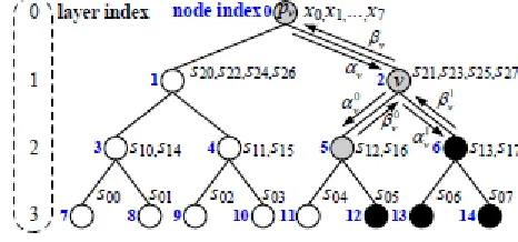
B. Prior Tree-Based SC Algorithms A polar code of block length N = 2n can also be represented by a full binary tree Gn of depth n, where each node of the tree is associated with a constituent code. For example, for node 1 shown in Fig. 2, the correspondent constituent code is the set f(s20; s22; s24; s26)g, where each
Fig. 1. Polar encoder with N = 8
Fig. 2. Binary tree representation of an (8, 3) polar code
element (s20; s22; s24; s26) relates to the data word u70 as shown in Fig. 1. The binary tree representation of an (8, 3) polar code is shown in Fig. 2, where the black and white leaf nodes correspond to information and frozen bits, respectively. There are three types of nodes in a binary tree representation of a polar code: rate-0 , rate-1 and arbitrary rate nodes. The leaf nodes of a rate-0 and rate-1 nodes correspond to only frozen and information bits, respectively. The leaf nodes of an arbitrary rate node are associated with both information and frozen bits. The rate-0, rate-1 and arbitrary rate nodes in Fig. 2 are represented by circles in white, black and gray, respectively.
From the root node, all nodes in a tree are activated in a recursive way for the SC algorithm. node is generated, the codeword x0N-1 can be obtained by combining and propagating ʋ up to the root node.
The SSC decoding algorithm
simplifies the processing of both rate-0 and rate-1 nodes. Once a rate-0 node is activated, it immediately returns the all zero vector. Once a rate-1 node is activated, a constituent codeword is directly calculated by making hard decisions on the received soft information vector. The ML-SSC decoding algorithm further accelerates the SSC decoding algorithm by performing the exhaustive-search ML decoding on some resource constrained arbitrary rate nodes, which are called ML nodes.
C. LLR Based List Decoding Algorithms For SCL decoding algorithms when decoding an information bit ui, each decoding path splits into two paths with ^ui being 0 and 1, respectively. Thus 2L path metrics are computed and the L paths correspond to the L minimum path metrics are kept. The list decoding algorithms are performed either on probability or logarithmic likelihood (LL) domain. In an LLR based list decoding algorithm was proposed to reduce the message memory
requirement and the computational
complexity of LL based list decoding algorithm.
IV. HIGH THROUGHPUT LIST
POLAR DECODER ARCHITECTURE
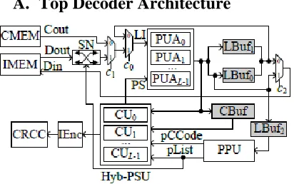
A. Top Decoder Architecture
Fig. 3. Decoder top architecture
In this paper, based on the proposed RLLD algorithm, a high throughput list decoder architecture, shown in Fig. 3, for polar codes is proposed. In Fig. 3, the channel message memory (CMEM) stores the received channel LLRs, and the internal LLR message memory (IMEM) stores the LLRs generated during the SC computation process. With the concatenation and split method in our prior work, the IMEM is implemented with area efficient memories, such as register file (RF) or SRAM. The proposed architecture has L groups of processing unit arrays (PUAs), each of which contains T processing units (PUs) and is capable of performing either the f or the g computation respectively.
designed based on the instruction RAM based methodology.
Both our high throughput list decoder architecture in Fig. 3 and that employ a partial parallel processing method. Besides, both architectures contain a channel message memory and internal message memory. However, compared to the architecture, the major improvements of our list decoder architecture are:
(a) Instead of LL messages, our high throughput list decoder architecture employs LLR messages, which result in more area efficient internal and channel message memories.
(b) The PPU in Fig. 3 implements our CG and MBS algorithms, while the PPU is just a sorter which selects L values among 2L ones. Due to the proposed PPU, our decoder
architecture achieves much higher
throughput.
(c) Our list decoder architecture employs a novel Hyb-PSU, which is more area and energy efficient. Our Hyb-PSU is based on the proposed index based partial sum computation algorithm. When a decoding path needs to be copied to another one, instead of copying partial sums directly our Hyb-PSU copies only decoding path indices. In contrast, the PSU copies path sums directly, which incurs additional energy consumption. Our Hyb-PSU stores most of the partial sums in area efficient memories, while the PSU stores all the partial sums in area demanding registers. Hence, our Hyb-PSU is scalable for larger block lengths.
B. Memory Efficient Quantization Scheme
For an SC or SCL decoder, the message memory occupies a large part of the overall decoder area. An SCL decoder needs a channel message memory and an internal message memory. For an LLR based SCL decoder, the channel memory stores N channel LLR messages. For a fixed
point implementation of our RLLD
algorithm, it is straightforward to quantize all LLRs in the internal memory with Q bits.
C. Proposed path pruning unit
When a rate-1 node with an FP node is activated, each decoding path splits into multiple ones and only the L most reliable paths are kept. The PPU in Fig. 3 implements our CG and MBS algorithms, and is responsible for calculating L returned code words, decoding path l copies from decoding path al before further decoding steps.
Take L = 4 as an example, the proposed PPU is shown in Fig. 4, which can be easily adapted to other L values. Our PPU in Fig. 4 has two types of node metric generation (NG) units, NG-I and NG-II, which compute the node metrics for a rate-1 node and an FP node, respectively. NG-Il and NGII l correspond to decoding path l. For decoding path l, the expanded path metrics PMj l ’s are obtained by adding the node metrics to the path metric PMl, which is stored in the path metric registers (PMR) and initialized with 0. When a rate-1 node is activated, NG-Il outputs two node metrics.
can be constructed with a BBS. When an FP node is activated, L NG-II modules implement the first part of our two-stage sorting scheme. For each decoding path, node metrics and their correspondent codewords are computed. The output expanded path metrics of the last stage of metric sorter are saved in the PMR.
Fig. 4. The proposed architecture for PPU
D. Proposed hybrid partial sum unit For the list decoder architectures, all partial sums are stored in registers and the partial sums of decoding path l0 are copied to decoding path l when decoding path l0 needs to be copied to decoding path l. The PSU needs single bit registers to store all partial sums, respectively. Thus, for large N, the register based PSU architectures are inefficient for two reasons. First, the area of the PSU is linearly proportional to N. For large N (e.g. N > 215), the area of PSU is large since registers are usually area demanding. Second, the power dissipation due to the copying of partial sums between different decoding paths is high when N is large.
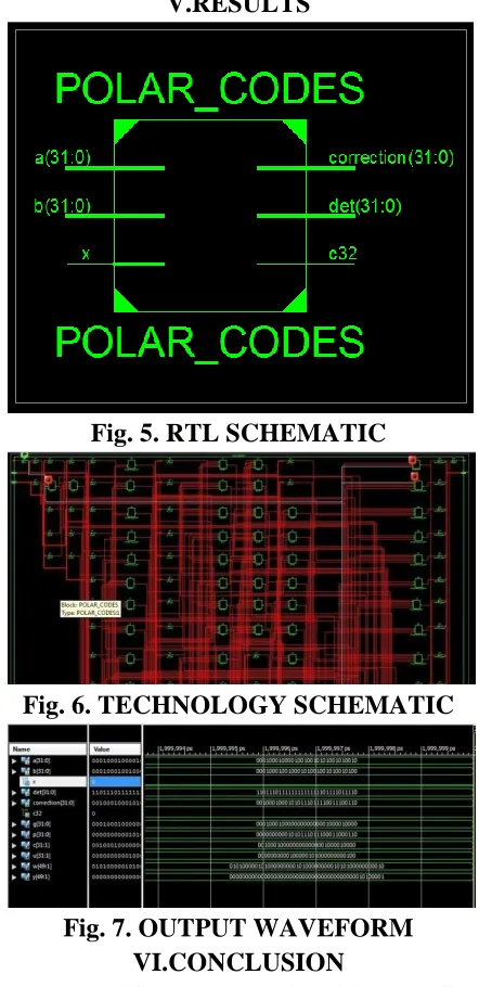
V.RESULTS
Fig. 5. RTL SCHEMATIC
Fig. 6. TECHNOLOGY SCHEMATIC
Fig. 7. OUTPUT WAVEFORM VI.CONCLUSION
demonstrate significant advantages over current state-of-the-art SCL decoders.
VII.REFERENCES
[1] E. Arıkan, “Channel polarization: A method for constructing capacity achieving codes for symmetric binary-input memory less channels,” IEEE Trans. Inf. Theory, vol. 55, no. 7, pp. 3051–3073, Jul. 2009.
[2] E. ¸Sa¸so˘glu, E. Teltar, and E. Arıkan, “Polarization for arbitrary discrete memoryless channels,” in Proc. IEEE Int.
Symp. Inf. Theory, Seoul, South Korea, Jun.
2009, pp. 144–148.
[3] G. D. Forney, Jr., “Codes on graphs: Normal realizations,” IEEE Trans. Inf.
Theory, vol. 47, no. 2, pp. 520–548, Feb.
2001.
[4] N. Hussami, S. B. Korada, and R. Urbanke, “Performance of polar codes for channel and source coding,” in Proc. IEEE
Int. Symp. Inf. Theory, Seoul, South Korea,
Jun./Jul. 2009, pp. 1488–1492.
[5] A. Eslami and H. Pishro-Nik, “On finite-length performance of polar codes: Stopping sets, error floor, and concatenated design,”
IEEE Trans. Commun., vol. 61, no. 3, pp.
919–929, Mar. 2013.
[6] U. U. Fayyaz and J. R. Barry, “Low-complexity soft-output decoding of polar codes,” IEEE J. Sel. Areas Commun., vol. 32, no. 5, pp. 958–966, May 2014.
[7] J. Xu, T. Che, and G. Choi. (2015). “XJ-BP: Express journey belief propagation decoding for polar codes.” [Online]. Available: http://arxiv.org/abs/1504.06025 [8] S. M. Abbas, Y. Fan, J. Chen, and C.-Y. Tsui, “Low complexity belief propagation polar code decoders,” in Proc. IEEE
WorkshopSignal Process. Syst. (SiPS), May
2015, pp. 1–6. [Online]. Available:
http://arxiv.org/abs/1505.04979
Authors:
H. Yasmeen studyingM.Tech (VLSI) from
Chaitanya Institute of Technology and Science, Warangal, Telangana,India.
R. Raju Kumar working as Assistant Professor in