ABSTRACT
BROOKS, DANIEL JOHN. The Effects of Neck Resection Level on the Initial Torsional Stability of Cementless Total Hip Arthroplasty in Dogs. (Under the direction of Ola Lars Anders Harrysson and Denis Jacques Marcellin-Little.)
The initial torsional stability of a cementless total hip arthroplasty (THA) is one
of the key factors in determining the biological fixation of the implant. The success of a
cementless hip replacement relies on the quantity and quality of bone ingrowth that
occurs. This study looked at the effects of femoral neck resection level on the initial
torsional stability of cementless THA in the canine population. Twenty paired cadaver
femurs were collected from dogs and implanted with canine cementless hip stems. One
femur from each pair was prepared with a neck cut with its medial aspect located at the
proximal aspect of the lesser trochanter (low neck cut) and the other with a neck cut with
its proximo-lateral aspect at the ossum collis femoris isthmus of the greater trochanter
and femoral neck (high neck cut). The specimens were then subjected to cyclic torque
loads in the caudal direction (Amplitude: -0.1 N-m to set torque) at four torque levels (1
N-m, 2 N-m, 4 N-m, and 6 N-m) and the torsional displacement, axial subsidence, and
strain were all recorded. A paired statistical analysis was completed so that specimens
from the same dogs could be compared to each other. The low neck cut group was found
to have significantly less micromotion than the high neck cut group during the 1 N-m and
4 N-m torque tests (p = 0.02 for both). Because the high neck cut specimens tended to
have more micromotion they may be apt to have lower quality bone ingrowth. A
significant difference was not found between the torsional displacements of the two
groups. The high neck cut specimens were found to have significantly (p = 0.02) more
0.22° which most likely does not indicate a clinically significant difference. No statistical
difference was found between the axial subsidence of the high and low neck cut
specimens other than at the 6 N-m level (p = 0.02). At 6 N-m the stems in the low neck
cut specimens had an average upward movement of 255 ± 310 µm while the stems in the
high neck cuts moved in the opposite direction and had an average downward movement
of 280 ± 695 µm. The low neck specimens were found to have significantly more canal
fill and implant impaction than the high neck cut specimens. This suggests that surgeons
need to be mindful that they may not insert stems as deeply in femurs prepared with high
neck cuts as they do in femurs with low neck cuts. This study was not able to show that
one neck cut level was superior to the other, however the data indicate that the low neck
cut group had slightly better stability based on having less micromotion at 1 N-m and 4
The Effects of Neck Resection Level on the Initial Torsional Stability of Cementless Total Hip Arthroplasty in Dogs
by
DANIEL JOHN BROOKS
A thesis submitted to the Graduate Faculty of North Carolina State University
in partial fulfillment of the requirements for the Degree of
Master of Science
Biomedical Engineering 2007
Raleigh, North Carolina
APPROVED BY:
____________________ ____________________
Dr. Denis J. Marcellin-Little Dr. C. Frank Abrams
____________________ ____________________
Dedications
My family and friends, for their undying support and encouragement.
My teachers, for passing on their knowledge and helping me to discover new things.
BIOGRAPHY
Daniel J Brooks was born to Kathleen and Conrad Brooks in the Fall of 1980 in
Dubuque, Iowa. He is the youngest of five children. As a young child his family used to
spend summers at their cottage in Popham Beach, Maine. In 1986 his family moved to
Rockport, Maine where he attended the public schools and graduated as an honors
graduate from Camden-Rockport High School in 2000. During high school he developed
a love for running and was a member of the cross-country and track teams. In 1998 he
qualified for and competed at the USATF National cross-country Junior Olympics. At the
completion of high school he was selected to be part of the MBNA Maine Scholars
program, which gave him a scholarship to attend the University of Maine and allowed
him to develop his professional skills through summer internships at the MBNA sites in
Camden and Belfast, Maine. While at the University of Maine he pursued a Bachelors of
Science in Bio-resource engineering and ran for the varsity track and field team as a
middle distance runner. When he finished his degree at the University of Maine in 2004
his advisor encouraged him to look at pursuing a graduate degree in Biomedical
Engineering in the new joint program at North Carolina State University and the
University of North Carolina at Chapel Hill. In the Fall of 2004 he entered the Joint BME
program to pursue a Masters of Science. For his first year at NC State he worked under
Dr. Peter Mente in the Tissue Mechanics Laboratory. He then took on a project working
with Dr. Ola Harrysson of the Industrial Engineering department and Dr. Denis
Marcellin-Little of the College of Veterinary Medicine. Upon completion of his work at
North Carolina State University he joined his wonderful girlfriend Emily in Ithaca, New
York where she is pursuing a PhD in biomedical engineering at Cornell University. He
recently accepted a position as a research support specialist in the Laboratory for
Therapeutic Tissue Engineering at Cornell University where he will do research on the
ACKNOWLEDGEMENTS
This work would not have been possible without the help and patience of a lot of people.
I would like to first thank the members of my advisory committee for guiding me and being
willing to help me solve problems. I would like to thank Dr. Frank Abrams for helping me to find
my way at NC State and always being willing to talk if I needed guidance, Dr. Peter Mente for
introducing me to many aspects of biomechanical testing and allowing me the use his lab, Dr. Ola
Harrysson for helping me to bridge the gap between engineering and medicine using medical
modeling, and finally Dr. Denis Marcellin-Little for allowing me into his world so I could get a
deeper understanding of orthopedics and clinical research. Everyone on my advisory committee
was able to help me in different ways and made this project possible.
This project was funded by grants from the American College of Veterinary Surgeons
(ACVS) and the Department of Clinical Sciences at North Carolina State College of Veterinary
Medicine. BioMedtrix donated the hip implants that were used in this project. This project would
not have been possible without the aid of support of those three organizations.
I would also like to acknowledge some fellow students who were willing to give a
helping hand when I needed it. Omer Cansizoglu was invaluable in the fabrication of the test
fixtures as well as giving me guidance on modeling, Dimitrios Makrozahopoulos assisted greatly
in preparing specimens and performing the testing, and Prasath Mageswaran gave me an amazing
amount of help and support throughout the project.
I also owe an enormous amount of gratitude to Carolyn Tate and the rest of the staff at
the Harnett County North Carolina Animal Shelter. Without their willingness to donate dog
cadavers, this project would have taken much longer to complete.
TABLE OF CONTENTS
Page
LIST OF FIGURES... vii
LIST OF TABLES... xi
1. INTRODUCTION...1
2. BACKGROUND 2.1 Evolution of Total Hip Replacement ...4
2.2 Canine Total Hip Replacement ...10
2.3 Cementless Hip Arthroplasty...14
2.3.1 Bone Ingrowth ...15
2.4 Effects of Neck Resection Level on Torsional Stability...20
2.5 Testing the Bone-Implant Interface ...24
2.6 Summary of Background ...30
3. HYPOTHESES...31
4. MATERIALS AND METHODS...32
4.1 In Vitro Testing 4.1.1 Specimen Preparation ...32
4.1.2 Specimen Testing...34
4.2 Statistical Methods...39
5. RESULTS...42
6. DISCUSSION...58
7. CONCLUSIONS...67
8. FUTURE WORK...68
8.1 Modeling Background 8.1.1 Finite Element Analysis...68
8.1.3 Quantitative Computed Tomography ...76
8.2 Modeling Methods 8.2.1 Modeling the Implanted Femur ...82
8.2.2 Finite Element Analysis...84
9. LIST OF REFERENCES...87
APPENDICES...91
Appendix 1. Results of Statistical Tests ...92
Appendix 2. Plots of Torsional Interface Displacement for each Specimen ...95
Appendix 3. Plots of the Axial Subsidence for each Specimen...115
Appendix 4. Specimen Information...135
Appendix 5. Procedure Used for Creating Models of Specimens ...137
LIST OF FIGURES Page
Figure 1 Radiographs of normal canine hip and canine hip with hip
dysplasia...10
Figure 2 Two neck resection levels used in the study. ...33
Figure 3 Placement of strain gages proximal to the neck cut...35
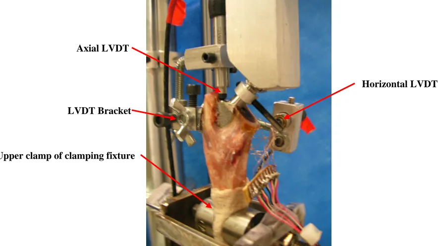
Figure 4 Specimen in testing setup...36
Figure 5 Coordinate pin-pointer used to measure the coordinates of key points for calculating torsional displacement...37
Figure 6 Test fixture used for applying loading ...38
Figure 7 Typical torsional displacement curve from a single torque test ...43
Figure 8 Plots of the total torsional displacement of the stem relative to the bone for each specimen and the difference in total torsional displacement at 1 N-m, 2 N-m, 4 N-m, and 6 N-m ...47
Figure 9 Plots of the micromotion of the stem relative to the bone for each specimen and the difference in micromotion at 1 N-m, 2 N-m, 4 N-m, and 6 N-...50
Figure 10 Plots of the axial subsidence of the stem relative to the bone for each specimen and the difference in axial subsidence at 1 N-m, 2 N-m, 4 N-m, and 6 N-m. ...53
Figure 11 Plots of the rotation of the implant in the bone and difference in rotation at 1.6 N-m and 3.2 N-m ...57
Figure 12 Definition of the material properties in Mimics ...84
Figure 13 Progression of model from bone to a finite element model...84
Figure A2.1 Torsional interface displacements of femur 7-Low during the 1 N-m, 2 N-m, 4 N-m, 6 N-m, and failure tests ...95
Figure A2.3 Torsional interface displacements of femur 8-Low during
the 1 N-m, 2 N-m, 4 N-m, 6 N-m, and failure tests. ...97
Figure A2.4 Torsional interface displacements of femur 8-High during
the 1 N-m, 2 N-m, 4 N-m, 6 N-m, and failure tests. ...98
Figure A2.5 Torsional interface displacements of femur 9-Low during
the 1 N-m, 2 N-m, 4 N-m, 6 N-m, and failure tests ...99
Figure A2.6 Torsional interface displacements of femur 9-High during
the 1 N-m, 2 N-m, 6 N-m, and failure tests ...100
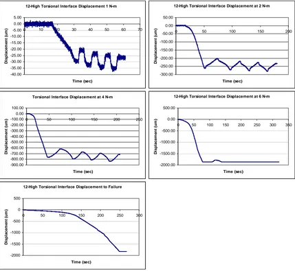
Figure A2.7 Torsional interface displacements of femur 12-Low
during the 1 N-m, 2 N-m, 4 N-m, 6 N-m, and failure tests...101
Figure A2.8 Torsional interface displacements of femur 12-High
during the 1 N-m, 2 N-m, 4 N-m, 6 N-m, and failure tests...102
Figure A2.9 Torsional interface displacements of femur 13-Low
during the 1 N-m, 2 N-m, 4 N-m, 6 N-m, and failure tests...103
Figure A2.10 Torsional interface displacements of femur 13-High
during the 1 N-m, 2 N-m, 4 N-m, and 6 N-m tests ...104
Figure A2.11 Torsional interface displacements of femur 15-Low
during the 1 N-m, 4 N-m, 6 N-m, and Failure tests ...105
Figure A2.12 Torsional interface displacements of femur 15-High
during the 1 N-m, 2 N-m, 4 N-m, and 6 N-m tests ...106
Figure A2.13 Torsional interface displacements of femur 16-Low
during the 1 N-m, 2 N-m, 4 N-m, 6 N-m, and failure tests...107
Figure A2.14 Torsional interface displacements of femur 16-High
during the 1 N-m, 2 N-m, 4 N-m, 6 N-m, and failure tests...108
Figure A2.15 Torsional interface displacements of femur 18-Low
during the 1 N-m, 2 N-m, 4 N-m, 6 N-m, and failure tests...109
Figure A2.16 Torsional interface displacements of femur 18-High
during the 1 N-m, 2 N-m, 4 N-m, and 6 N-m tests ...110
Figure A2.17 Torsional interface displacements of femur 19-Low
Figure A2.18 Torsional interface displacements of femur 19-High
during the 1 N-m, 2 N-m, and 4 N-m tests ...112
Figure A2.19 Torsional interface displacements of femur 20-Low
during the 1 N-m, 2 N-m, 4 N-m, 6 N-m, and failure tests...113
Figure A2.20 Torsional interface displacements of femur 20-High
during the 1 N-m, 2 N-m, 4 N-m, 6 N-m, and failure tests...114
Figure A3.1 Axial Subsidence of the implant in femur 7-Low during
the 200 N preload, 1 N-m, 2 N-m, 4 N-m, 6 N-m, and
Failure tests. ...115
Figure A3.2 Axial Subsidence of the implant in femur 7-High during
the 200 N preload, 1 N-m, 2 N-m, 4 N-m, 6 N-m, and
Failure tests. ...116
Figure A3.3 Axial Subsidence of the implant in femur 8-Low during
the 200 N preload, 1 N-m, 2 N-m, 4 N-m, and 6 N-m tests...117
Figure A3.4 Axial Subsidence of the implant in femur 8-High during
the 1 N-m, 2 N-m, 4 N-m, 6 N-m, and Failure tests. ...118
Figure A3.5 Axial Subsidence of the implant in femur 9-Low during
the 200 N Preload, 1 N-m, 2 N-m, 4 N-m, 6 N-m, and
Failure tests. ...119
Figure A3.6 Axial Subsidence of the implant in femur 9-High during
the 200 N Preload, 1 N-m, 2 N-m, 4 N-m, 6 N-m, and
Failure tests. ...120
Figure A3.7 Axial Subsidence of the implant in femur 12-Low during
the 200 N Preload, 1 N-m, 2 N-m, 4 N-m, 6 N-m, and
Failure tests. ...121
Figure A3.8 Axial Subsidence of the implant in femur 12-High during
the 200 N Preload, 1 N-m, 2 N-m, 4 N-m, and 6 N-m
tests. ...122
Figure A3.9 Axial Subsidence of the implant in femur 15-Low during
the 200 N Preload, 1 N-m, 2 N-m, 4 N-m, 6 N-m, and
Failure tests. ...123
Figure A3.10 Axial Subsidence of the implant in femur 13-High during
the 200 N Preload, 1 N-m, 2 N-m, 4 N-m, and 6 N-m
Figure A3.11 Axial Subsidence of the implant in femur 15-Low during the 200 N Preload, 1 N-m, 4 N-m, 6 N-m, and Failure
tests ...125
Figure A3.12 Axial Subsidence of the implant in femur 15-High during
the 200 N Preload, 1 N-m, 2 N-m, 4 N-m, and 6 N-m
tests. ...126
Figure A3.13 Axial Subsidence of the implant in femur 16-Low during
the 200 N Preload, 1 N-m, 2 N-m, 4 N-m, 6 N-m, and
Failure tests ...127
Figure A3.14 Axial Subsidence of the implant in femur 16-High during
the 200 N Preload, 1 N-m, 2 N-m, 4 N-m, 6 N-m, and
Failure tests. ...128
Figure A3.15 Axial Subsidence of the implant in femur 18-Low during
the 200 N Preload, 1 N-m, 2 N-m, 4 N-m, 6 N-m, and
Failure tests. ...129
Figure A3.16 Axial Subsidence of the implant in femur 18-High during
the 200 N Preload, 1 N-m, 2 N-m, 4 N-m, and 6 N-m
tests ...130
Figure A3 .17 Axial Subsidence of the implant in femur 19-Low during
the 200 N Preload, 1 N-m, 2 N-m, 4 N-m, 6 N-m, and
Failure tests. ...131
Figure A3.18 Axial Subsidence of the implant in femur 19-High during
the 200 N Preload, 1 N-m, 2 N-m, and 4 N-m tests...132
Figure A3.19 Axial Subsidence of the implant in femur 20-Low during
the 200 N Preload, 1 N-m, 2 N-m, 4 N-m, 6 N-m, and
Failure tests ...133
Figure A3.20 Axial Subsidence of the implant in femur 20-High during
LIST OF TABLES Page
Table 1 Torsional displacement during the 1 N-m test ...43
Table 2 Torsional displacement during the 2 N-m test...44
Table 3 Torsional displacement during the 4 N-m test...45
Table 4 Torsional displacement during the 6 N-m test...46
Table 5 Axial subsidence for each specimen at 1 N-m, 2 N-m, 4 N-m, and 6 N-m. ...52
Table 6 Rotation of stem in the bone at 1.6 N-m and 3.2 N-m...56
Table A1.1 Results of statistical tests ...93
Table A1.2 Results of statistical tests for the strain data ...94
Table A4.1 Information on dogs used for study. ...135
Table A4.2 Canal fill and impaction level for each specimen ...136
Table A6.1 Strain (µε) in each Specimen at 1 N-m of Torque ...141
Table A6.2 Strain (µε) in each Specimen at 2 N-m of Torque ...142
Table A6.3 Strain (µε) in each Specimen at 4 N-m of Torque ...143
Table A6.4 Strain (µε) in each Specimen at 6 N-m of Torque...144
1. INTRODUCTION
Total hip replacement (THR), or total hip arthroplasty (THA) as it is also known, is a
common procedure that is used to treat debilitating conditions of the hip in both human and
veterinary medicine. Presently about 170,000 human THR surgeries are done each year in the
U.S. (AAOS 2003). THR involves the replacement of a diseased natural hip joint (femoral
head and acetabulum) with an intramedullary stem with a head that fits into an acetabular
cup. In the canine population the primary reason for THR is osteoarthritis (OA) in the hip as
a result of canine hip dysplasia (CHD)(Olmstead 1995). CHD is a condition where the
femoral head is forced out of the acetabulum in the dorsolateral direction due to uneven
growth between the skeletal and muscular systems in the developing hip (Morgan, Wind et
al. 2000). OA is a non-inflammatory disease that results in the wear and degeneration of the
cartilage tissue that protects articulating joints. Canines with hip dysplasia are prone to
developing OA due to the excessive wear that occurs as a result of the abnormal development
of their hips. OA can result in pain and stiffness and can be a very debilitating condition if
untreated. Other conditions that may be indications for THR in dogs are chronic hip
luxations, avascular necrosis of the femoral head, idiopathic arthritis in older dogs, mal-union
of fractures in the hip, and various degenerative joint diseases (Montgomery, Milton et al.
1992; Olmstead 1995).
Currently canine THR surgeries are performed using either a cemented or
noncemented hip system. When canine THR first became popular in the 1970’s almost all
procedures were done with a cemented hip system that used a cement such as
polymethylmethacrylate (PMMA) to bond the prosthetics to the bone. Cemented THR was
et al. 1983; Montgomery, Milton et al. 1992). The use of bone cement was associated with
complications such as aseptic loosening due to erosion of the bone by enzymatic degradation,
increased chances of infection, and neurapraxia due to the bone cement being in contact with
nerves during its exothermic setting process. Due to the complications that were associated
with cemented THR there was a desire to find alternatives to using bone cement to fixate hip
systems. Throughout the 1970’s and 80’s researchers worked on developing the technologies
necessary to create a successful noncemented (cementless) hip system. Cementless hip
systems have porous coatings and rely on friction and bone ingrowth to stabilize the stem and
acetabular cup in the bone. The porous coating on the prosthesis allows for bone to grow into
the surface of the prosthesis and biologically fixate the prosthesis.
In order for a noncemented THR to be successful it is necessary to have enough bone
ingrowth to stabilize the prosthesis. There are three factors that play a major role in
determining the extent and quality of bone ingrowth that occurs. Those factors include the
type of porous coating that the prosthesis has, the blood supply to the bone-implant interface,
and the amount of relative motion that occurs between the hip stem and the proximal femur
(Pilliar 2005). The last factor mentioned is of particular interest and is the focus of this
project.
Many studies have looked at the affects that relative motion has on the development
of biological fixation (Cameron, Pilliar et al. 1973; Pilliar, Lee et al. 1986; Engh, Bobyn et
al. 1987; Engh, O'Connor et al. 1992; Bragdon, Burke et al. 1996). Motion of the stem
relative to the femur can lead to the formation of fibrous tissue ingrowth instead of bone
ingrowth. Fibrous tissue ingrowth does not provide as much stability and is therefore not as
may be a failure of any bone ingrowth to occur. In this case there is poor biological fixation
and the prosthesis will be unstable. Unstable prostheses can lead to complications such as
thigh pain, stem loosening, and subsidence. It is often necessary to do a revision THR
surgery if there is a lack of good biological fixation. In this study torsional stability will be
one of the main focuses because of the high torsional loads that the hip usually experiences
during daily activities. Some researchers suggest that torsional stability is the most important
factor involved with the loosening of the stem within the proximal femur (Sugiyama,
Whiteside et al. 1989; Harman, Toni et al. 1995).
The goal of this project was to test the effects of femoral neck resection level on
initial stability of a cementless hip replacement and to generate data for validating a
modeling procedure to predict the initial stability of canine cementless hip stems immediately
after they are implanted. The neck resection level is the level at which the neck of the femur
is cut when preparing it to be inserted. In vitro testing was done where the displacement of
the stem was measured relative to the bone. Paired testing was done to compare the effects of
neck resection level on the stability of the initial bone-implant interface. Pairs of femurs were
collected from dogs and one femur from each pair was placed in one of two groups. The first
group of femurs was implanted using a low neck cut (a neck cut with its medial aspect
located at the proximal aspect of the lesser trochanter) and the second group was implanted
with a high neck cut (a neck cut with its proximo-lateral aspect at the ossum collis femoris
isthmus of the greater trochanter and femoral neck). This procedure allowed for a comparison
of the affects of neck cut on the initial stability of the bone-implant interface. Following
implantation a material testing machine was used to test both the axial and torsional stability
This project is important because it will help to develop knowledge about the initial
bone-implant interface in cementless canine THR and will help surgeons to determine
whether a low or high neck resection should be used. Valuable information was gained about
the effects of neck cut, a topic on which very little has been published. The data form this
study will also prove useful in validating a finite element model for the torsional stability of
cementless hip implants. Doing in vivo or in vitro testing can be difficult and expensive.
Having a modeling procedure that allows for new designs to be validated could therefore be a
very valuable tool when designing new prostheses. The results of this project should prove to
be helpful to veterinary professionals as well as those working in the design of both canine
and human hip prostheses.
2. BACKGROUND
2.1 Evolution of Total Hip Replacement in Humans
The evolution of total hip replacement (THR) has largely been a story of finding
adequate materials and fixation methods. Over the years advances in materials and
fabrication techniques have helped to continually improve implant design. Materials that
were used in early implants had problems with fatigue, wear resistance, and biocompatibility
among other things (Amstutz and Clarke 1991). While material technology has greatly
improved, problems still persist with the materials of which modern implants are made.
There are continual efforts to find materials with better wear characteristics and that have
stiffnesses that closely match bone. Fixation methods are also something that has continually
improved throughout the evolution of THR. Early hip systems used screws to fixate the
components of the prosthesis. Screw fixated systems where replaced by cemented systems in
cementless hip systems (Amstutz and Clarke 1991). Today about an equal number of
cemented and noncemented THR are performed each year in humans (AAOS 2003). Over
the long history of THR many experiments and studies have been done that have helped to
improve our knowledge of hip arthroplasty. From these studies it has been possible to
improve implant materials, design, and fixation methods.
The idea of replacing the diseased hip joint with an artificial hip is not a new idea; it
is one that has been around for over a century. In 1891 Gluck did one of the earliest hip
arthroplasties. Gluck replaced a hip using an ivory ball and socket (AAOS 2003). The ball
and socket were fixated using nickel-plated screws along with a cement that consisted of
plaster of Paris and pumice powder. Gluck’s design was unsuccessful in large part due to a
lack of material compatibility with the body. Before THR could be successful there would
have to be advances in material science in order to find adequate materials. Prior to World
War II the development of an acceptable hip replacement was slowed by a lack of adequate
materials. The materials that were available were susceptible to wear in the body and the
presence of wear particles increased the chances of infection. In the 1930’s Smith-Peterson
began testing different materials for making acetabular cups for unilateral hip replacement
(Smith-Peterson 1939; Smith-Peterson 1948). In these unilateral hip replacements, a cup
would be inserted into the acetabulum into which the existing head of the femur would sit.
Smith-Peterson made acetabular cups out of materials such as Pyrex (Corning Inc, Corning,
NY), Bakelite (Bakelite Limited, Birmingham, England), and Vitallium (Stryker Corp.,
Allendale, NJ) in search of a material that would be more biocompatible and wear resistant.
Smith-Peterson’s work was a step towards finding a low friction interface at the joint
replacements by Wiles, Moore, Bohlman, and F.R. Thompson (Bohlman 1952; Wiles 1958;
Amstutz and Clarke 1991). The hip stems that were developed by Moore and Thompson are
still implanted in human patients today and have remained largely unchanged (AAOS 2003).
In 1951 Mckee introduced a hip replacement system that consisted of a cobalt chromium
(CoCr) stem and socket (McKee 1966). Initially CoCr screws were used to fixate the stem
and the socket, but by the mid 1960’s McKee modified his design so that the stem and socket
could be fixated using an acrylic cement (Amstutz and Clarke 1991; AAOS 2003). McKee’s
design was the first total hip replacement system that was clinically available in the United
States.
The switch to using cement to fixate the components of prostheses was due in large
part to the work of Sir John Charnley, who is considered to be the father of the modern hip
arthroplasty. Charnley was instrumental in developing a method to cement implants as well
as looking for materials that could be used to make better hip implant systems. In 1960
Charnley released a report advocating the use of polymethylmethacrylate (PMMA) bone
cement for fixation of hip implants (Charnley 1960). PMMA is a self-curing cement that was
originally developed for fixating dental prostheses. Charnley suggested that PMMA could be
used to surround the prosthesis and act as an interface between the bone and the implant. As
a result of Charnley’s recommendations, the 1960’s saw the development and release of
numerous cemented hip implant systems. PMMA is still the primary cement that is used in
cemented hip systems.
Charnley and his colleagues also worked on finding a material that would provide
better wear resistance in the hip implant (Charnley, Kamangar et al. 1969). From their work
bearing surface resulted in very little wear. Having a metal head coupled with a UHMWPE
socket would reduce the chances of wear particles as well as reduce the chances of the
implants wearing out and needing to be replaced. UHMWPE is still used in the bearing
surfaces of hip implants today; however it is not the ideal material because it still produces
some wear particles. Therefore efforts are still being made to find a suitable material to
replace UHMWPE (AAOS 2003).
In the 1970’s there was a movement towards using biological fixation instead of
cement. It was known that cemented prostheses were prone to loosening over time due to
failure of the bone-cement interface, and that an alternative to cemented fixation needed to be
pursued. The advent of porous coated hip stems provided an attractive alternative to
cemented stems. The theory behind porous coated stems is that the bone surrounding the
stems will grow into the porous coating and a “biologic” fixation will be created (Cameron,
Pilliar et al. 1973; Engh, Bobyn et al. 1987; Amstutz and Clarke 1991). During this time,
cementless stems were introduced by Judet, Lord, Harris, and Galante among others. The
most popular porous coated stems were the porous coated anatomic (PCA), anatomic
medullary locking (AML), and Harris-Galante (HG) stems. Pilliar and others were
instrumental in developing the idea of creating a microporous beaded sintered coating on hip
stems to improve biological fixation (Pilliar, Cameron et al. 1975). The beaded surfaces were
made of small 20 to 150 µm beads around which bone could grow around and attach.
The 1970’s also saw the introduction of the use of ceramics such as alumina for the
bearing surfaces of implants as well as the introduction of modular hip prostheses (Amstutz
and Clarke 1991). It was believed that ceramic on ceramic bearing surfaces would exhibit
surfaces were found to have wear rates that were too high (AAOS 2003). Ceramic
components were also found to have a high risk of fracture if they were not aligned correctly.
Modular hip prostheses are prostheses where the femoral stem and head can be selected
separately and then connected together. Early designs for modular hip prostheses had
problems with bonding of the ceramic ball and metal stem (Amstutz and Clarke 1991).
Originally epoxies were used to bond the ball and stem together, but doing so often resulted
in a bond that lost strength over time eventually resulting in separation. There were also
problems with the fixation of ceramic acetabular components. Because of these problems
along with others, it was not until 2003 that the first ceramic-on-ceramic hip systems were
approved by the FDA for use in the U.S. (AAOS 2003). Prior to that ceramics were used for
polyethylene-on-ceramic bearing surfaces where a ceramic ball was inserted into a
UHMWPE socket. The UHMWPE-on-ceramic bearing surface has similar wear
characteristics to those found with a metal-on-UHMWPE interface.
Since the beginning of the 1980’s efforts have been made to improve implant design
to achieve better fixation and decrease some of the adverse affects of THR such as stress
shielding and aseptic loosening. Stress shielding is when an implant prevents the bone from
experiencing the stresses that are usually put on the bone. Because the bone isn’t
experiencing as much stress the bone starts to remodel and deteriorate. Aseptic loosening is
when wear particles from the implant cause macrophage to release enzymes that cause the
bone around the implant to deteriorate. As the bone around the implant deteriorates it causes
the implant to loosen. In order to prevent aseptic loosening it is necessary to use materials
that are resistant to wear. Advances were made for both cemented and noncemented
identify the affects that different design parameters and surgical techniques have on the
success of THR (Schneider, Eulenberger et al. 1989; Sugiyama, Whiteside et al. 1989;
McKellop, Ebramzadeh et al. 1991; Engh, O'Connor et al. 1992; Rashmir-Raven, DeYoung
et al. 1992; Harman, Toni et al. 1995; Ramamurti, Orr et al. 1997; Viceconti, Monti et al.
2001). While there was a movement towards cementless techniques, cemented THR has
remained a popular method for treatment in many patients. The Finnish Registry reports that
since the late 1980’s, that in Finland a little over 40% of the THR that were done in humans
were cementless (AAOS 2003). There is a tendency for cementless techniques to be used in
younger patients who are more active (Rothman and Cohn 1990; AAOS 2003). This is
because the cement interface tends to break down fairly quickly in active patients (Rothman
and Cohn 1990). Amstutz suggests that in humans, cementless techniques should be used if
there is a good chance that revision will be needed in the future (Amstutz, Yao et al. 1991).
This is due to the fact that it is more difficult to revise a cemented THR because there is less
bone stock present following implantation with a cemented hip implant. When a cementless
hip implant is used it leaves more bone that can be used in future revision surgeries.
Therefore cemented techniques should only be used in cases where the prospect for needing
revision is low. Cementless THR have proven to have long-term fixation once ingrowth
occurs, while cemented arthroplasties tend to lose fixation over time as the cement interface
fatigues and breaks down. Because the fatigue of the cement interface is not as much of
concern in older patients that are less active, cemented THRs are often done in that
2.2 Canine Total Hip Replacement
With the success of THR for the treatment of noninfectious coxofemoral joint
diseases in humans, it was logical for veterinary medicine to adopt the procedure for
treatment in animals. THR has been a successful method of treating canine hip dysplasia
(CHD), which is a condition where the femoral head becomes displaced in the dorsolateral
direction (Figure 1). Currently for dogs that have the indications for THR, there is about a
95% clinical success rate for returning the dogs to normal or near normal function (Olmstead
1995). One of the earliest attempts of hip arthroplasty in animals were unipolar arthroplasties
performed by Brown on cats and dogs in 1953 (Montgomery, Milton et al. 1992). Gorman
reported doing the first canine total hip replacements in 1957, when he preformed the surgery
in working military dogs (Gorman 1962; Montgomery, Milton et al. 1992). However many
of the early canine hip prostheses proved to be unsuccessful because they were made from
inadequate materials. Early prostheses had bearing surfaces that coupled stainless steel with
materials such as Teflon, vinylidine fluoride resin, or stainless steel. These bearing surfaces
had excessive wear and proved to be inadequate (Hoefle 1974).
Figure 1. Radiographs of normal canine hip and canine hip with hip dysplasia. Left: Radiograph of normal canine hip. Note how the femoral head matches the curvature of the acetabulum. Right: Radiograph of canine hip with dysplasia. The femoral head has migrated out of the acetabulum and there are signs of bone deterioration (Images from www.biopet.com).
part to the fact that many human hip implants are initially tested in the canine population.
The designs of canine hip implants therefore often parallel the design of human hip implants.
The most noticeable difference between canine and human hip implants is size. Canine hip
implants are generally smaller in size than hip implants for humans due to the fact that dogs
have relatively smaller femurs. Some other noticeable differences between canine and human
hip implants are the shape and neck angle of the hip stems. The difference in shape and neck
angle of the stems is due to the differences in the geometry of canine and human femurs.
The first canine hip prosthesis that was found to be successful was the cemented
Richards-Toronzo type prosthesis that was introduced in the early 1970’s (Montgomery,
Milton et al. 1992). The Richards-Toronzo type prosthesis was a three-component prosthesis
that consisted of stainless steel femoral stem and acetabular cup with a UHMWPE head.
Hoefle reported successful results with the Richards-Toronzo type prosthesis in a case study
that he did with a hunting dog (Hoefle 1974). The Richards-Toronzo type prosthesis was
eventually revised to produce the Richards II cemented prosthesis (Leighton 1979; Olmstead,
Hohn et al. 1983). The Richards II prosthesis was a fixed head prosthesis and was the first
canine prosthesis that was extensively tested and found to have long-term success. Leighton
did a small clinical study with nine dogs using the Richards II prosthesis (Leighton 1979). In
the study the outcome was excellent for all of the dogs except for one that got an infection
and had to be withdrawn from the study. Olmstead et al. did a five-year study of the Richards
II prosthesis with 221 hip replacements on 190 dogs (Olmstead, Hohn et al. 1983). This more
comprehensive study found the Richards II prosthesis to have a success rate of 91.2%. Some
(8.7%), aseptic loosening (2.2%), and neurapraxia (2.2%) associated with PMMA being in
contact with the nerves around the proximal femur.
In the late 1980’s Howmedica introduced the canine porous coated anatomic (PCA)
hip prosthesis (DeYoung, DeYoung et al. 1992; Marcellin-Little, DeYoung et al. 1999). The
PCA hip prosthesis was cementless and relied on bone ingrowth into its porous coating for
fixation. Despite the success that was achieved with cemented THR, there was a desire to try
to find alternatives to using cement to fixate prostheses. The use of PMMA cement was
associated with increased chances of infection, neurapraxia, excessive loosening over time,
and longer surgery times (Rothman and Cohn 1990; Montgomery, Milton et al. 1992).
DeYoung et al. did a preliminary study where they completed 100 arthroplasties with the
PCA canine total hip system (DeYoung, DeYoung et al. 1992). This study had a 6% rate of
complications and only a 2% rate of failure. The complications that were experienced were
luxations of the hip, fissure fractures, and in one case the acetabular component became
totally displaced. Marcellin-Little et al. did a long-term follow-up study to the initial study
done by DeYoung et al. (Marcellin-Little, DeYoung et al. 1999). This follow-up study
involved doing a clinical and radiological evaluation of 50 consecutive arthroplasties done
with the PCA total hip system. Biological fixation with bone ingrowth was found to occur for
all of the acetabular cups and femoral stems. In this study the six-year survival rate of the
PCA total hip system was found to be 87%. Five out of the seven failures were due to
dislocations that were associated with the placement of the cementless acetabular cups.
Based on their results Marcellin-Little et al. concluded that the PCA total hip system had
In 1990 a canine modular THR system was introduced that gave surgeons more
options when doing total hip replacements (BioMedtrix, Boonton, NJ). In a modular hip
system the hip stem and femoral head are separate components. This differed from the
previously available fixed head systems where the stem and head were one piece. Some of
the advantages of the modular system over a fixed head system are that the modular system
allows for different neck lengths to be achieved and gives the surgeon the option to use
different stem/head combinations to get a better fit (Olmstead 1995). With the modular
system, heads are available with different hole depths to allow for different neck lengths to
be achieved. This allowed the surgeon to select the stem that best fits the femur and then
select the corresponding head that will give the correct neck length. With a fixed head
prosthesis the surgeon would often have to make compromises between stem fit and neck
length. Olmstead described the procedure for implanting a modular hip prosthesis and also
did a preliminary clinical study (Olmstead 1995). The clinical study looked at the outcome of
52 hip replacements with modular hip prostheses. Olmstead found the outcomes with fixed
head and modular hip prostheses to be similar. However he suggested that the modular
system would offer surgeons more versatility and allow them to better treat dogs of different
breeds and sizes. Today both cemented and noncemented modular hip systems are available
for the canine population.
There are a variety of aspects that need to be considered when determining whether a
cemented or noncemented THR would be better for a particular patient (Rothman and Cohn
1990; Amstutz and Namba 1991; Montgomery, Milton et al. 1992). In humans the main
concerns are age, activity level, and prospects for needing revision. Traditionally, in humans,
dogs, cemented hip replacements have been found to have significant loosening after 5-7
years (Morgan, Wind et al. 2000). Some of the advantages of cemented over cementless
THR are that cemented procedures provide immediate stability, result in less blood loss, and
provide immediate pain relief (Amstutz, Yao et al. 1991). With cementless procedures the
stability is not very good until biological fixation begins to occur. This means that there is an
initial waiting period after cementless THR during which there is limited stem stability and
pain may persist. Therefore depending on the age of a dog, a cemented THR may be a good
option because of its immediacy. If the dog is not expected to live longer than 5-7 years a
cemented THR is a very good option. The advantages of cementless over cemented THR are
that the cementless technique provides long-term stability, results in less bone loss, and does
not have the biocompatibility issues that are involved with cement use (Rothman and Cohn
1990; Montgomery, Milton et al. 1992). While the initial stability of cementless THR is not
very good, once biological fixation occurs, the stability of cementless THRs has been found
to be very good and deteriorates very little over time (Rothman and Cohn 1990). This makes
cementless THR a good choice for younger dogs that are apt to live longer than the expected
life of a cemented hip replacement. Currently the majority of canine THRs are cemented but
there is a movement towards using cementless techniques.
2.3 Cementless Hip Arthroplasty
Cementless hip arthroplasty relies on press fit and biological fixation for stability.
Modern cementless femoral stems usually have some sort of a porous coating that allows for
bone ingrowth into the prosthesis. The porous coating can consist of sintered powders,
screens, meshes, fibers, or plasma-sprayed surfaces (Amstutz and Namba 1991; Pilliar 2005).
seen on prosthesis today. Plasma spray-coatings are created by doing a spray deposition of
either a metal or ceramic onto the prosthesis. The materials used for plasma spray coating
include titanium and calcium phosphate. Creating sintered porous surfaces involves sintering
or diffusion bonding metal powders or fibers onto the surface of the implant. Usually a
Co-Cr-Mo or Ti6A14V powder is used for sintered surfaces. The small gaps in the surfaces
provide places for bone to grow into the surface to provide attachment. Factors such as pore
size, the initial stability, and the vascularity of the bone play a role in the extent and quality
of biological fixation (Cameron, Pilliar et al. 1973; Pilliar, Cameron et al. 1975; Pilliar, Lee
et al. 1986; Engh, Bobyn et al. 1987; Engh, O'Connor et al. 1992; Bragdon, Burke et al.
1996; Pilliar 2005). Prior to bone ingrowth, the initial stability of the hip stem relies on the
friction and the press-fit that is present at the bone-implant interface. The initial stability of
the implant is a primary determinate of whether or not bone ingrowth occurs and is therefore
a key factor in determining the success of cementless hip replacements. Implant design and
surgical technique play major roles in determining the initial stability of the hip stem and
ultimately the success of the THR operation.
2.3.1 Bone Ingrowth
Ingrowth of bone into the porous surface of an implant is essential in order for the
implant to have long-term stability. In order for bone ingrowth to occur the conditions at the
bone-implant interface must be right. Three important requirements are a porous surface with
adequate size pores, having very little movement of the stem relative to the proximal femur,
and having adequate vasculature in the bone to support bone growth (Pilliar 2005). Properly
designing the prostheses and using proper surgical techniques helps to ensure that the
The size of the pores in the porous coating of a hip stem can greatly influence the
strength of the bone-implant interface that forms (Robertson, St. Pierre et al. 1976; Amstutz
and Namba 1991; Bragdon, Jasty et al. 2004; Pilliar 2005). Pilliar has done extensive
research on ingrowth into porous surfaces and suggests that a minimum pore size of 100 µm
is required for ingrowth to occur (Pilliar 2005). Pores smaller than 100 µm may prevent bone
from migrating into the porous coating. Robertson et al. inserted porous coated metal rods
(10 mm long, 4.8 mm diameter) into the medial cortex of the femora of dogs (Robertson, St.
Pierre et al. 1976). The pore size of the coating on the rods ranged from a polished smooth
surface with no pores to a beaded surface with 50 µm by 125 µm minimum pore size. The
dogs were put into four different groups and the rods were left in situ for periods of 2 to 8
weeks depending on the group. At the end of the in situ period the dogs were sacrificed and
their femora were harvested. Push-out tests were completed to determine the interfacial shear
strength of the interface between the porous rod and the bone. The results of the testing
indicated that the interfacial shear strength increased with pore size and healing time. Cook
used rods with minimum pore sizes of 155, 235, and 350 µm and varying numbers of porous
layers (Cook, Walsh et al. 1985).. They found that increasing the number of porous layers up
to a point increased the shear strength of the interface. They found that having adding layers
beyond three layers did not increase the interface shear strength. Cook’s study also found that
there was not a significant difference between the shear strengths achieved with the three
different pore sizes. Today it is common practice to use pore sizes in the range of 100-500
µm and a porosity of 30%-50% (Pilliar 2005).
Movement of the hip stem relative to the femur can greatly affect bone ingrowth
O'Connor et al. 1992; Bragdon, Burke et al. 1996). Excessive relative motion can inhibit
bone ingrowth and may promote the development of fibrous tissue (Bragdon, Burke et al.
1996). Fibrous tissue ingrowth does not provide as much stability as bone ingrowth and is
therefore less favorable (Pilliar, Lee et al. 1986; Viceconti, Monti et al. 2001). Various
studies have been done to look at the affects of micromotion on bone ingrowth. There is a
consensus among the studies that micromotion needs to be kept to a minimum in order to
ensure bone ingrowth.
Cameron et al. did an early study looking at ingrowth into porous coated Vitallium
staples that were inserted in the tibiae of dogs (Cameron, Pilliar et al. 1973). In this study
tibial osteotomies were performed on a test group of dogs and then reduced using porous
coated Vitallium staples. The osteotomies were not perfectly reduced because the goal of the
study was to look at the affects that relative movement had on bone ingrowth. The control
group in the study consisted of dogs in which an osteotomy was not performed but a porous
staple was still inserted. After four months the dogs were sacrificed and their tibiae were
harvested. A materials testing machine was used to determine the force required to pull the
staple out of the bone. After the staple was pulled out it was examined for signs of ingrowth.
The test group was found to lack any ingrowth into the porous surface of the staple, while the
control group was found to have obvious bone ingrowth. From their study Cameron et al.
concluded that ingrowth will not occur in the presence of excessive motion.
Bragdon et al. did a study to examine the effects of micromotion on tissue ingrowth
into porous implants (Bragdon, Burke et al. 1996). In this study porous rods were implanted
into the cancellous bone of the distal femur in 20 mature dogs. The rods protruded though the
the rod to oscillate with a set amount of micromotion (0, 20, 40, or 150 µm). The interface
oscillated the rod at 0.5 Hz for eight hours a day to simulate the load bearing that usually
occurs each day. The interface contained sensors to measure the applied torque and
displacement that occurred with each oscillation. The experiment was continued for six
weeks and then the dogs were sacrificed so that histologic studies could be completed. The
stiffness of the interface was measured based on the torsional resistance per angular
displacement (units: N-m/deg). The average interface stiffness for the 20 µm group increased
from 0.88 ± 0.25 N-m/deg immediately after the operation to 1.25 ± 0.45 N-m/deg at the end
of the six-week period. The average interface stiffness for the 40 µm group actually
decreased from 0.77 ± 0.43 N-m/deg to 0.54 ± 0.13 N-m/deg over the course of the
six-weeks. The average interface stiffness of the 150 µm group decreased as well, as it went
from 0.25 ± 0.1 N-m/deg to 0.16 ± 0.1 N-m/deg. The histologic study showed that the 0 and
20 µm groups had bony ingrowth while the 40 µm group had a mixture of fibrocallus and
bony ingrowth. The 150 µm group had some bony ingrowth but fibrous tissue was the
predominant tissue that formed at the interface. Based on their results, Bragdon et al.
concluded that micromotion of 20 µm or less is suitable for bone ingrowth and formation of a
high stiffness interface, while greater amounts of micromotion resulted in less desirable
ingrowth.
A study that is often cited when discussing the affects of micromotion on bone
ingrowth is a study by Pilliar et al. (Pilliar, Lee et al. 1986). The first half of this study
focused on the bone ingrowth into porous hip stems in the presence of micromotion. Porous
hip stems were loosely inserted into the femurs of adult beagles such that they were not snug
bearing after the operation. One year post-op the dogs were sacrificed and radiographs were
taken prior to in vitro testing of the bone-implant interface. The radiographs revealed that
some of the stems had cancellous bone ingrowth, while others had fibrous tissue attachment.
In vitro testing of the implanted femurs involved loading the stems in tension and
compression to get load deflection curves. Based on their testing Pilliar et al. concluded that
micromotion greater than 150 µm was sufficient to prevent cancellous bone ingrowth into the
porous surface of hip implants, and that for micromotion greater than 150 µm, fibrous tissue
ingrowth will occur instead of bony ingrowth. Pilliar et al. therefore suggest trying to obtain
a snug fit when inserting cementless hip stems in order to limit micromotion and encourage
bone ingrowth.
Engh et al. did a human clinical and histologic study to look at porous-coated hip
replacements and factors affecting bone ingrowth and stress shielding (Engh, Bobyn et al.
1987). The clinical study involved 307 human subjects who were examined 2 years
post-operation and 89 who were examined 5 years post-post-operation. The histologic study included
11 subjects who had passed away. For the clinical study, radiographs were taken to examine
the bone-implant interface and determine the extent of bone remodeling that had occurred.
The bone-implant interface was classified as being fixed by bone ingrowth, stable fibrous
ingrowth, or unstable. In the clinical study 259 cases (84%) had fixation by bone ingrowth,
42 cases (13%) had stable ingrowth with fibrous tissue, and 7 cases (2%) were determined to
be unstable. In the histologic study of 11 subjects it was found that 9 of the cases had bone
ingrowth, while two had fibrous tissue ingrowth. From their studies Engh et al. concluded
that in order to achieve bone fixation it is necessary to have a tight fit at the isthmus
make fixation less likely. They suggested that if the stem fills the medullary canal, that the
prognosis will be good for bone ingrowth. Engh et al. also stressed that it is important not to
use stems that are too large because they will have higher rigidity and be apt to cause more
stress shielding.
2.4 Effects of Neck Resection Level on Torsional Stability
The level of femoral neck resection has been found to play a significant role in the
torsional stability of cementless hip prostheses (Freeman 1986; Nunn, Freeman et al. 1989;
Pipino and Molfetta 1993; Whiteside, White et al. 1995). Resecting the femoral neck at a
higher level leaves more bone in the proximal region of the femur resulting in improved
proximal stress distribution and torsional stability (Pipino and Molfetta 1993). Clinically and
experimentally the area around the femoral neck has been found to be prone to resorption
following THA (Huiskes, Weinans et al. 1989; Huiskes 1990; Sumner and Galante 1992).
While it has been suggested that retention of the femoral neck may just lead to greater neck
resorption, studies have found that neck retention does not significantly increase bone
resorption (Freeman 1986; Pipino and Molfetta 1993). Studies indicate that as much of the
femoral neck as possible, should be retained in order to provide greater proximal stem
stability as well as to leave bone that can be utilized in future revision surgeries (Freeman
1986; Nunn, Freeman et al. 1989; Pipino and Molfetta 1993; Whiteside, White et al. 1995).
Freeman reviewed the reasons why the femoral neck is removed during THA and
came to the conclusion that there isn’t a valid reason for resecting the femoral neck (Freeman
1986). The three main reasons that Freeman identified for removing the femoral neck were
surgical convention, fear of impingement, and the danger of calcar (femoral neck) resorption.
and Muller had a curved shape and were easier to insert if much of the femoral neck was
removed, and that thus it became surgical convention to resect the femoral neck even when
inserting straight stems. Freeman argues that the straight stems that are used today can easily
be inserted with much of the femoral neck left intact, and that there is no reason other than
convention why the femoral neck should be removed when inserting modern hip stems.
Another reason for neck resection is impingement or the striking of the acetabular cup by the
femoral neck. With early prosthesis designs, acetabular cups subtended 180°, which resulted
in increased chances of impingement if the femoral neck was not removed. Freeman
suggested that with new acetabular cups that only subtend 140° it is possible to retain the
femoral neck without having impingement occur. The danger of calcar (medial cortex of the
remaining neck) resorption is another reason why many surgeons remove the femoral neck.
Freeman completed a study looking at calcar resorption and found that about 70% of the
blood flow to the femoral neck is retained after THA and that the vitality of the bone is good
(Freeman, Rasmussen et al. 1986). Freeman also found very little radiographic evidence of
calcar resorption occurring when the femoral neck was retained. Looking at the main reasons
for femoral neck resection, Freeman advocated that femoral neck resection is unjustified and
that the femoral neck should be retained whenever possible.
Pipino and Molfetta (1993) also advocate the retention of the femoral neck when a
THA is performed. They advocate neck retention because they believe that it provides better
tri-planar stem stability, allows for proximal cortical fixation, causes stresses to be
transmitted along physiological lines, and also preserves bone that can be used during future
revision surgeries. When the neck is retained, the proximal portion of the hip stem is
surface of the femoral neck provides the support for the hip stem. When the neck is
maintained it helps to transmit the stresses in a way that is similar to the way that stresses are
transmitted in the un-implanted femur. Maintaining normal stress transmission helps to
reduce bone loss due to bone remodeling. Retaining the femoral neck also makes revision
surgeries easier to perform because more bone stock remains into which the new stem can be
inserted. Pipino and Molfetta reported on a study where they examined the outcome (1 to 5
years post-operation) of 200 cementless THAs where the neck was retained. In the study,
only 2% of the cases showed signs of bone resorption and 91% of the cases had a clinical
outcome of good or excellent according to the Harris rating system. The subjects of the study
were found to have a lack of thigh pain, suggesting that the femoral stems had good tri-planar
stability. Based on their findings and the findings of others, Pipino and Molfetta suggest that
the femoral neck should be retained because of the role that it can play in providing stability
and distributing stresses.
Nunn et al. (1989) did a study that examined the torsional stability of both cemented
and noncemented hip stems that were inserted and tested with the femoral neck left intact as
well as with the femoral neck resected (Nunn, Freeman et al. 1989). Initially, cemented and
noncemented hip stems were implanted into human cadaver femurs that were prepared with a
higher than normal neck cut for total hip replacement. A load of 400 N was applied to the
necks of the stems in the anterior-posterior direction. The rotational displacement was
monitored during the testing. The necks of the femurs where then resected to the level that is
conventionally used for total hip replacement surgeries (across the medio-superior base of the
greater trochanter to the point midway between the lesser trochanter and the junction
the displacements that resulted during the loading. The study found that displacements were
less when the neck cut was higher than normal. They also found that the mean displacement
of the cemented stems was less than the mean displacement measured for the cementless
stems. Nunn et al. suggested that the femoral neck be retained during total hip replacement
because it increases the rotational stability of the prosthesis.
A study done by Whiteside et al. looked at the effects of using four different levels of
neck resection on the torsional stability of cementless total hip replacement (Whiteside,
White et al. 1995). The study involved performing torsional testing on 20 human cadaver
femora that were separated into four groups. The four groups consisted of femora that were
resected such that 100%, 50%, 15%, or 0% of the femoral neck remained. The femoral neck
was considered to be the bone that is above the lesser trochanter on the medial aspect of the
bone. The femora were implanted with cementless stems and then were loaded in torsion to
cause internal rotation. Initially a load of 5 Nm was applied to the implanted specimens.
Progressively larger loads were applied in 2.5 Nm increments up to 20 Nm. Micromotion and
interface slippage were recorded during and after the loading respectively. Failure was said to
occur if fracture occurred or if motion exceeded 1 mm during the loading. The torsional
stability of the group where 100% of the femoral neck was left intact was significantly better
than the other three groups where all or part of the femoral neck was removed. The 100% and
50% neck preservation groups had similar motion at 20 Nm of load, but the 15% and 0%
preservation groups had significantly more motion. Whiteside et al. suggest that while
retaining all of the femoral neck will provide the best torsional stability it is probably just
achieve adequate stability. Removing more than 50% of the femoral neck significantly
reduces the torsional stability of cementless hip stems.
2.5 Testing the Bone-Implant Interface
Various methods have been used to test the bone-implant interface that exists in the
implanted femur following THR. Using different methods researchers have been able to
measure parameters such as relative implant motion, strain, and the stiffness of the interface.
Most methods utilize some sort of a material testing machine that is able to apply axial or
torsional loads to the implanted femur. Some studies have used trans-cortex displacement
transducers to determine relative motion (also known as subsidence) directly at the
bone-implant interface (Schneider, Eulenberger et al. 1989; Engh, O'Connor et al. 1992;
Vanderby, Manley et al. 1992), while others have measured the global relative motion of the
stem using displacement transducers that are connected to the top of the stem (Sugiyama,
Whiteside et al. 1989; McKellop, Ebramzadeh et al. 1991; Rashmir-Raven, DeYoung et al.
1992; Harman, Toni et al. 1995). Using these methods researchers have been able to gain
valuable insight into effects that different implant parameters, surgical techniques, and
loading conditions have on the dynamics of the bone-implant interface.
Vanderby et al. compared the initial and four-month post-operative stability of
cementless and cemented hip stems in dogs (Vanderby, Manley et al. 1992). Five large dogs
were implanted with cementless stems and another five dogs were implanted with cemented
stems. Both the implanted and normal femurs were harvested from the dogs four-months
post-operation. The normal femur from each dog was then implanted using the same
procedure that was used for the implanted femur of the respective dog. The newly implanted
implantation. The specimens were tested by applying loads to the head of the implant in the
axial (100, 400, and 800 N), craniocaudal (100 N), and mediolateral (100 N) directions. The
displacements were measured at the neck and mid-stem of the implants using transcortices
Eddy current transducers. The results of the testing showed that the initial stability of the
cemented stems was significantly better than the initial stability of the cementless stems, but
that after four months of bone ingrowth the stabilities of the cemented and noncemented
implants were not significantly different. Torsional loading was found to produce the greatest
relative displacements. Radiographs were used to determine the bony apposition into the
cementless stems. From this it was found that a linear increase in bony apposition resulted in
an exponential decrease in relative displacement.
A study done by Schneider et al. looked at developing a method of doing in vitro
testing of the initial stability of cementless hip prostheses in the human femur (Schneider,
Eulenberger et al. 1989). With their method the distal end of the femur was removed and the
end of the truncated femur was potted into a PMMA cup. The experimental setup included an
Instron materials testing machine with an x-y-table at its base that allowed for measurement
of the horizontal displacement using LVDTs. The shaft of the prosthesis was attached to the
load cell of the Instron and the potted end of the femur rested in a socket that was attached to
the x-y-table. The femur was fitted with interface transducers to measure the motion at the
bone-stem interface. The interface transducers consisted of a trans-cortex pin that rests
against the stem on one end and a strain gauge at the other end. The rotation of the stem
relative to the bone was measured by a precision potentiometer with a resolution better than
0.002°. With the setup both axial and torsional loads could be applied and the resulting
cementless stems and one cemented stem. Based on their testing Schneider et al. believed
that their testing method is a valid way to compare cementless hip prostheses designs and
accurately measure the axial and rotational motion at the bone-stem interface.
Engh et al. did in vitro testing to quantify the micromotion that occurred in implanted
femurs that were retrieved from humans at autopsy (Engh, O'Connor et al. 1992). In the
study fourteen femurs with anatomic medullary locking hip stems were retrieved and tested.
The in vivo duration of the implantation of the stems ranged from 12 to 87 months. The distal
femurs were potted in cement and the heads of the implants were loaded with an axial torque
along with an axial force. The loading regimen was supposed to simulate the loading that is
encountered during stair climbing. Micromotion was measured using three electrical
displacement transducers that had press fit metal pins that went through both cortices and the
prosthesis. The electric displacement transducers allowed for both rotation and subsidence to
be measured. 13 of the 14 cases displayed bone ingrowth into the porous coating of the
implant. With these cases the maximum micromotion was found to be 40 µm, and the motion
was found to be elastic, meaning that the displacement was recovered once the load was
removed. One of the 14 cases did not display bone ingrowth and had 150 µm of
micromotion. In this study the prosthesis had varying amounts of porous coating. Engh et al.
found that the amount of micromotion was directly related to the extent of porous coating.
Meaning that more porous coating results in less micromotion.
Sugiyama et al. did an in vitro study to examine the rotational stability of both
cemented and uncemented hip stems (Sugiyama, Whiteside et al. 1989). The study was done
with 24 human femur specimens. The specimens were divided into four groups including
preparation with hand mixed and packed cement, and normal canal preparation with vacuum
mixed cement and injection with a cement gun. After implantation the distal end of the femur
was potted and a collar with an LVDT was mounted on the proximal femur just below the
implant collar. The LVDT was placed against a flag on the collar of the stem and allowed for
the movement of the stem to be determined relative to the proximal femur. A torque collar
was then placed around the neck of the stem such that the torque would rotate the stem about
the long axis of the femur. Acoustic emission sensors were placed on the outside of the femur
to aid in evaluating failure of the bone or implant during loading. Torsional loads were then
applied to the stem in a ramp waveform with increasing amplitude until failure occurred.
Sugiyama et al. found that the uncemented hip stems had the greatest amount of subsidence
and the lowest failure torque of the stems that were tested. They suggest that the upper femur
may not have the capacity to resist torsional loading of uncemented hip implants when they
are initially implanted. Because of this they believe that torsional loading may be the primary
cause of loosening of cementless hip stems. They also found that during testing, signs of
cement mantle failure were appearing at physiologically torsional loads. From this Sugiyama
et al. concluded that torsional loading is something that needs to be considered for both
cemented and uncemented hip replacements.
McKellop et al. compared the stability of various press-fit hip stems with the stability
of a cemented stem by doing testing with synthetic human femora (McKellop, Ebramzadeh et
al. 1991). Synthetic femora were implanted with one of four cementless stems or a cemented
one according to the manufacture’s recommended insertion procedure. The femora were then
fitted with collars each with three displacement transducers to measure axial, medial-lateral,