ISSN (Print) : 2320 – 3765 ISSN (Online): 2278 – 8875
I
nternational
J
ournal of
A
dvanced
R
esearch in
E
lectrical,
E
lectronics and
I
nstrumentation
E
ngineering
(A High Impact Factor, Monthly, Peer Reviewed Journal)
Website: www.ijareeie.com
Vol. 7, Issue 6, June 2018
Design of Digital Power Scope using TI
MSP430G2553 Microcontroller
Vishal Raman Gaikwad
Assistant Professor, Dept. of Electronics Engineering, Walchand College of Engineering, Sangli, Maharashtra, India
ABSTRACT:A dual channel Digital Oscilloscope with one channel dedicated to Voltage and other to Current signal was designed using LM324 Quad Operational Amplifier, MSP430G2553 Microcontroller and JHD12864E Graphics Liquid Crystal Display. It displays waveform and wave parameters like, maximum, minimum and period. It is suitable for observing the nature of voltage and current signals in Power Electronics circuit.
KEYWORDS:Firmware, Hardware, Microcontroller, OPAMP, Power Electronics, etc.
I.INTRODUCTION
An Oscilloscope is a measuring Instrument used to observe voltage signal at a test point in an Electrical or Electronic circuit. There are two types of oscilloscopes; Analog oscilloscope and Digital oscilloscope. Analog oscilloscope use Cathode Ray Tube (CRT) to display waveform and it is heavy. Digital oscilloscope use Thin Film Transistor (TFT) display to display waveform and is comparatively light. Digital oscilloscope can store waveforms in its memory or on Pen drive and can be connected to a Computer. However oscilloscopes are not affordable to all beginners and Hobbyist [1][2][3][4][8]. Oneoptionis to connecting a Data Acquisition module to a Personal Computer and convert it into a digital oscilloscope [5][6][10]. This paper presents the design of a low cost digital oscilloscope capable of simultaneously displaying voltage and current waveform at corresponding test point in a power electronics circuit.
II. HARDWARE
This Power Scope contains the following four basic building blocks.
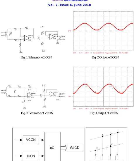
A. Current Conditioner (ICON)[9]
The circuit diagram of Current Conditioner (ICON) is shown in Fig. 1[9]. Alternating Current (AC) of up to 5A is sensed using 5A to 5mA Current Transformer (CT). The output of CT is converted into voltage using floating ground type current to voltage converter. A Direct Current (DC) voltage of +1.5V is added to the output of current to voltage converter, to get a unipolar output signal (typically 0 to 3V). The output of ICON is connected to A0 pin of the MSP430G2553 microcontroller. The output of ICON for 4.35A of AC current, drawn by 1000W heater load, is shown in Fig. 2. The output waveform was captured using Aplab 36025D dual channel colour Digital Storage Oscilloscope (DSO).
B. Voltage Conditioner (VCON)[9]
Fig. 1 Schematic of ICON Fig. 2 Output of ICON
Fig. 3 Schematic of VCON Fig. 4 Output of VCON
ISSN (Print) : 2320 – 3765 ISSN (Online): 2278 – 8875
I
nternational
J
ournal of
A
dvanced
R
esearch in
E
lectrical,
E
lectronics and
I
nstrumentation
E
ngineering
(A High Impact Factor, Monthly, Peer Reviewed Journal)
Website: www.ijareeie.com
Vol. 7, Issue 6, June 2018
C. Microcontroller
Texas Instruments MSP430G2553 is a 16 bit RISC microcontroller available in 20 pin Dual In line Package (DIP). It has two 8 bit ports, one Watchdog timer, two 16 bit timers each with three capture compare modules, one Universal Serial Communication Interface , one 8 channel 10 bit Analog to Digital Converter (ADC), one 8 channel analog comparator, 512 bytes of RAM and 16kB of Flash memory. Besides this it has on chip Digitally Controlled Oscillator (DCO) and supports five low power modes. The 8 data pins of JHD12864E are connected to P2 and 6 control pins are connected to P1. ADC of MSP430G2553 has programmable sample and hold time, software or hardware controlled start of conversion, supports four conversion modes and has Data Transfer Controller (DTC). Channels A0 and A1 of ADC are sampled periodically at an interval of 200us using hardware controlled start of conversion and sequence of channel conversion mode.
D. Graphics LCD (GLCD)
JHD12864E is 128x64 dots graphics LCD with 8 bit parallel interface. It has two 64x64 dots display controller. The GLCD is used to display either voltage waveform only, or current waveform only, or both voltage and current waveforms, or voltage waveform and its parameters, or voltage waveform and its parameters.
III.FIRMWARE
The block diagram of digital power scope using MSP430G2553 microcontroller is shown in Fig. 5. The firmware for the power scope performs the following three operations,
1. Reads 128 equally spaced samples of analog voltage at A0 and A1 as array I and array V respectively
2. Measures period and finds maximum and minimum values in array I and V
3. Displays waveform and wave parameters on GLCD.
ADC of MSP430G2553 has eight analog inputs, A0 to A7. Reading the analog voltage at A0 and A1 provides the information about current and voltage respectively. However, the analog voltage at A0 and A1 is read sequentially so it represents the current and voltage at different time instance. This time difference is equal to the sum of, sample and hold time and conversion time. Linear interpolation [12] is used to calculate the current at the time instant when voltage was read. In Fig. 6, TS is the time interval between two successive voltage or current samples (i.e, V1 and V2 or I1 and I2) and TD is the time interval between nth voltage and current sample (i.e, V2 and I2). With the current signal linear in the interval TS; the current I2S at the time instant of V2 is given by the equation,
= + − ( − )
A voltage trigger point is set in software to make the display stable. In order to display low current waveform an amplifier is implemented in software. Using a push button connected in pull down to the Non Maskable Interrupt (NMI) pin one of five display modes is selected. The five display modes are; voltage waveform only, current waveform only, voltage and current waveform, voltage waveform with parameters and current waveform with parameters.
VCON divides input voltage by Kv (typically 217). The output of VCON is mapped to an integer number from 0 to 1023 by ADC. Therefore, the voltage wave parameters, minimum and maximum, are found by multiplying output of ADC by Kv*Vref/1023 (typically 0.63). Vref is the reference voltage applied to ADC. Similarly, ICON divides input current by Ki (typically 4.71). The output of ICON is mapped to an integer number from 0 to 1023 by ADC. Therefore, the current wave parameters, minimum and maximum, are found by multiplying output of ADC by Ki*Vref/1023 (typically 0.01).
Voltage Waveform Current Waveform
Voltage and Current Waveform Voltage Waveform with Parameters
Current Waveform with Parameters
Readings observed on Digital Multimeter
Voltage across 1000W heater 230V
Current flowing through 1000W heater 4.35A
Readings observed on Power scope
Vmax 351.24V
Vmin -330.24V
Imax +6.83A
Imin -6.83A
V.CONCLUSION
ISSN (Print) : 2320 – 3765 ISSN (Online): 2278 – 8875
I
nternational
J
ournal of
A
dvanced
R
esearch in
E
lectrical,
E
lectronics and
I
nstrumentation
E
ngineering
(A High Impact Factor, Monthly, Peer Reviewed Journal)
Website: www.ijareeie.com
Vol. 7, Issue 6, June 2018
REFERENCES
[1] Liberty Mutauranwa, MalvinNkomo, "Design and realization of a compact low cost system-on-chip based digital audio oscilloscope", Advances in Computing and Communication Engineering (ICACCE) 2016 International Conference on, pp. 442-448, 2016.
[2] VladNiculescu, Adrian IoanLiţă, "Open source oscilloscope for hobby users", RoEduNet International Conference - Networking in Education and Research (RoEduNet NER) 2015 14th, pp. 203-207, 2015.
[3] A. Wagh, Z. Dave, G. Singh, V. Dange, A. Tambe, S. Gengaje, "A low cost portable oscilloscope for educational platforms using a Programmable System on Chip", Advances in Communication and Computing Technologies (ICACACT) 2014 International Conference pp. 1-4 2011-4.
[4] Ishtiak Ahmed Karim, “A low cost portable oscilloscope based on Arduino and GLCD”, 2014 International Conference on Informatics, Electronics & Vision (ICIEV),pp 1-4, 2014.
[5] Yong Zheng, Xiaohan Guan, Yuquan Wang and Wenjia Li, "Design for portable virtual instrument with USB interface," International Conference on Automatic Control and Artificial Intelligence (ACAI 2012), Xiamen, 2012, pp. 799-802.
[6] J. Li, P. Ren, X. Fang, H. Zhang and S. Zhang, "The design and development of PDA for electricians," 2011 International Conference on Computer Science and Service System (CSSS), Nanjing, 2011, pp. 839-842.
[7] V. R. Gaikwad and S. N. Kore, "Modeling and Simulation of Single Phase Half Bridge Shunt APF", IOSR Journal of Electrical and Electronics Engineering, vol. 1, pp. 30-38, May-June 2012.
[8] A. Trivedi, M. Awad, "ARM Based Handy and Portable Oscilloscope Using Graphical Display" Int. J. of Eng. Research and Appl. vol. 5 no. 3 pp. 106-109 Mar. 2015.
[9] V. R. Gaikwad, "Single Phase Power Factor and Total Harmonic Distortion Monitoring System", AICTE Sponsored National Conference on Recent Trends in Electronics Engineering, pp. 108-111, 7-9 June 2013.
[10] V. R. Gaikwad, IrfanAktar, Nagmothi et al,"PC Based Plotter," Final year B.E.project, Dr. J. J. Magdum College of Engineering, Department of Electronics Engineering, Jaysingpur, 1998-1999, ShivajiUniversity Kolhapur.
[11] George J. Wakileh, “Power Systems Harmonics Fundamentals, Analysis and Filter design”, Springer 2010.