LDGM Codes for Channel Coding and Joint
Source-Channel Coding of Correlated Sources
Wei Zhong
Department of Electrical and Computer Engineering, University of Delaware, Newark, DE 19716, USA Email:[email protected]
Javier Garcia-Frias
Department of Electrical and Computer Engineering, University of Delaware, Newark, DE 19716, USA Email:[email protected]
Received 2 October 2003; Revised 3 October 2004
We propose a coding scheme based on the use of systematic linear codes with low-density generator matrix (LDGM codes) for channel coding and joint source-channel coding of multiterminal correlated binary sources. In both cases, the structures of the LDGM encoder and decoder are shown, and a concatenated scheme aimed at reducing the error floor is proposed. Several decoding possibilities are investigated, compared, and evaluated. For different types of noisy channels and correlation models, the resulting performance is very close to the theoretical limits.
Keywords and phrases:channel coding, LDPC codes, LDGM codes, iterative decoding, correlated sources, joint source-channel coding.
1. INTRODUCTION
The introduction of turbo codes [1] and low-density parity check (LDPC) codes [2,3,4,5] has been one of the most im-portant milestones in channel coding during the last years. Provided that the information block lengths are long enough, performance close to the Shannon theoretical limit can be achieved for different channel environments. However, in practical applications, complexity issues have to be carefully considered, since both schemes present either high encod-ing or high decodencod-ing complexity. Specifically, for the case of turbo codes the encoding complexity is very low, but the de-coding complexity is high. Compared with turbo codes, stan-dard LDPCs present a higher encoding complexity, but the decoder is simpler.
In this paper, we first show that it is possible to achieve a channel coding performance comparable to that of standard
This is an open access article distributed under the Creative Commons Attribution License, which permits unrestricted use, distribution, and reproduction in any medium, provided the original work is properly cited.
This work was partially supported by NSF Grant CCR-0311014 and pre-pared through collaborative participation in the Communications and Net-works Consortium sponsored by the US Army Research Laboratory un-der the Collaborative Technology Alliance Program, Cooperative Agreement DAAD19-01-2-0011. The US Government is authorized to reproduce and distribute reprints for Government purposes notwithstanding any copyright notation thereon.
LDPC and turbo codes by utilizing systematic linear codes with low-density generator matrices [6] (LDGM codes1).
LDGM codes present a complexity advantage over standard LDPC and turbo codes. Specifically, because of the sparseness of the generator matrix, the amount of processing required in the encoder is linear with the block size and similar to that of turbo codes. Moreover, since the parity check matrix of sys-tematic LDGM codes is also sparse, such codes are in fact a subset of LDPC codes and can be decoded in the same man-ner and with the same complexity as standard LDPC codes. Notice, however, that in order to facilitate the development of the paper, we will derive the decoding algorithm utilizing the graph corresponding to the generator matrix.
In the second part of the paper, we will focus on the use of LDGM codes to perform joint source-channel coding of cor-related sources, which includes the case of pure source coding as a particular case. The problem of coding for multitermi-nal correlated sources has important practical applications (e.g., in the context of sensor networks [9]). Since compres-sion and joint source-channel coding of correlated sources can be considered as a problem of channel coding with side information [10,11], the use of powerful channel codes, such as LDGM codes, should produce very good results in this
context. The first schemes for compression of multitermi-nal correlated sources using channel codes were proposed in [12,13,14], and the use of turbo-like codes in this problem was proposed in [15,16]. However, although as shown in [17,18] the separation principle between source and channel coding holds for transmission of correlated sources over sep-arated noisy channels, it is not straightforward to implement a practical system based on this concept. One of the reasons is that, in spite of some previous work (see [14,19] and the references therein), the problem of designing good practical codes for correlated sources from a source coding perspective is still open. Moreover, the separation between source and channel coding may lead to catastrophic error propagation. Previous work in joint source-channel coding using iterative decoding schemes (turbo and LDPC codes) for the cases in which only one source is corrupted by noise (and the spe-cial case of joint source-channel coding for single sources) can be found in [20,21,22,23,24]. The case in which both sources are transmitted through separated noisy channels has appeared only in [25,26], where turbo codes were proposed to perform joint source-channel coding of correlated sources. The contents of this paper are as follows:Section 2 in-troduces systematic LDGM codes and presents the decoding algorithm in relation with that of standard LDPC codes. The proposed concatenated scheme, required to eliminate the er-ror floor in both channel coding and joint source-channel coding, is introduced in Section 3.Section 4contains sim-ulation results for the case of channel coding with LDGM codes over binary symmetric channels (BSC), and additive white gaussian noise (AWGN) and Rayleigh fading channels. The rest of the paper deals with the problem of joint source-channel coding of correlated sources. The theoretical limits for this problem are presented in Section 5, and the ratio-nale for using turbo-like codes in this context is explained inSection 6.Section 7specifies the proposed system and the correlation model utilized in this paper for joint source-channel coding of correlated sources. Simulation results are provided in Section 8. Finally,Section 9concludes the pa-per, and a comparison between the decoding complexity of LDGM and turbo codes is provided in the appendix.
2. SYSTEMATIC LDGM CODES FOR CHANNEL CODING
2.1. Encoding
Systematic LDGM codes are linear codes with a sparse gen-erator matrix, G = [I P] with P = [pkm] and thus the corresponding parity check matrix is H = [PTI]. We de-note the information message that we want to transmit as
u = [u1· · ·uK]. These bits, together with the coded bits
generated as c = uP, with c = [c1· · ·cM], are
transmit-ted through a noisy channel. The corruptransmit-ted sequence at the decoder is denoted as [u c], where cm = cm + e1
m and
u
k =uk+e2k, withem1 andek2being the noise introduced by
the channel. Notice that the proposed code is systematic with rateK/N, whereN=K+M. In this paper, we will denote as regular (X,Y) LDGM codes those irregular systematic LDPC
c1 c2 c3
Qx
mk Rxmk
u1 u2 u3 u4 u5 u6
Figure1: Bipartite graph representing an LDGM code.{cm} repre-sent the coded bits generated at the encoder (before being corrupted by the channel).{uk}are the nodes corresponding to the systematic bits. The figure shows the two different types of messages that are propagated in the decoding process through the graph.
codes in which all theN−Kcheck nodes have degreeY+ 1, all theKsystematic bit nodes have degreeX, and each of the
N−K coded bit nodes has degree 1 and is associated to its corresponding check node. In other words, the parity matrix
Pof an (X,Y) LDGM code has exactlyXnonzero entries per row andY nonzero entries per column. We will also abuse this notation to include irregular LDGM codes whoseaverage degree distributions are also (X,Y) (i.e., the average number of nonzero entries per row and per column in their matrices
P isXandY, resp.) In any case, it is obvious that the rela-tionship between the code rate and the degree distributions is given by
Rc=XY+Y . (1)
2.2. Decoding algorithm
For the case of LDPC codes, the decoder goal is to iteratively estimate the most probable solution of the equations=eHT, wheresrepresents the syndrome calculated from the received sequence,H is the parity check matrix of the code, andeis the error pattern that we are interested in calculating (the sparsest one satisfying the equation above). Analogously, we can see LDGM decoding as a method to find the most prob-able solution for the equationc=uP, wherecis the vector of coded bits generated at the encoder (i.e., before they are corrupted by the channel noise),G=[I P] is the generator matrix of the code, anduis the information message that we want to calculate.Figure 1shows the graph associated with the proposed code.
The decoding algorithm for LDGM codes can be derived by applying belief propagation [27] (or factor graph decod-ing [28]) over the graph described inFigure 1. The applica-tion of belief propagaapplica-tion for the proposed codes presents an important difference with respect to standard LDPC codes: in standard LDPC codes, the syndrome nodes are fixed to a deterministic value (i.e., for each position they are either 0 or 1). In the proposed codes, the coded bit nodescare ran-dom variables, with distribution calculated depending on the received corrupted coded bitscand the distribution of the noise vectore1(i.e.,c
m=cm+e1 m).
proposed codes achieve good performance. In order to facil-itate the algorithm implementation, we present the decod-ing method indicatdecod-ing only the modifications with respect to the case of standard LDPC codes. Using the notation com-monly utilized in the LDPC literature, we will denote byrmkx ,
x ∈ {0, 1}, the message propagated from coded bit nodecm to systematic bit nodeuk(and byqxmk,x∈ {0, 1}the message propagated from systematic bit nodeuk to coded bit node
cm), if the standard LDPC decoding algorithm were to be
di-rectly applied over the graph shown inFigure 1. We now in-dicate the modifications necessary to deal with LDGM codes. The messages passed from coded bit nodes to systematic bit nodes will be denoted byRxmk.Qxmkindicate the messages ex-changed from systematic bit nodes to coded bit nodes.
(1) Initialization.Fix the probability of the systematic bit nodes to itsa priorivalue. For every (m,k) such that
uk andcm are connected, letQmkx = Px
k = 1−pk if
u
k = x, andQxmk = Pxk = pk if uk = x, withx ∈
{0, 1}.pkdenotes the probability that systematic bituk is received in error.
(2) Message passing from the coded bit nodes to the system-atic bit nodes.
(i) For every (m,k) pair such thatukandcmare con-nected, calculatermkx as in standard LDPC decod-ing (but usdecod-ing the parametersQxmkinstead ofqmkx ). (ii) CalculateRxmkas
R0 mk=
1−γmrmk0 +γmrmk1 , (2)
R1 mk=
1−γmrmk1 +γmrmk0 , (3)
whereγmdenotes the probability that coded bitcm is received in error. The intuitive idea behind the previous equations is that when the received coded bit is in error (which occurs with probabilityγm) the message to pass, Rxmk, is notrmkx , but rmk1−x. If the received coded bit is correct (which occurs with probability 1−γm),Rxmk=rmkx .
(3) Message passing from the systematic bit nodes to the coded bit nodes.For every (m,k) pair such thatukand
cmare connected, calculateQxmkin the same way asqmkx
is calculated in standard LDPC decoding. The only dif-ferences are that now parametersRxmkshould be used instead ofrmkx , and that thea prioriprobability for the systematic bit nodeuk isPkx = 1−pkifuk =x, and
Px
k=pkifuk=x, withx∈ {0, 1}.
3. CONCATENATED LDGM SCHEMES
As shown in [29], and first recognized by MacKay [5], LDGM codes are bad codes, since they present error floors that are independent of the block length. Specifically, LDGM codes with small degrees have high error floors but good conver-gence thresholds, while the contrary occurs if the degrees are high [29]. However, these error floors can be reduced and practically eliminated. The reason is that, as explained in [29] for BSCs, the number of errors for the blocks in er-ror decays very fast, provided that the crossover probability
Outer LDGM code
Inner LDGM code
K/N1 N1/N
Figure2: Concatenated scheme of LDGM codes to reduce the er-ror floor. First, the information message is encoded by a high rate
K/N1outer LDGM code. The output is encoded by a rateN1/N in-ner LDGM code to produce a rateK/Noverall code.
cout
cin
u
Figure 3: Graph associated with the concatenated LDGM codes with cin as the inner coded bit nodes,cout as the outer coded bit nodes, anduas the information (systematic) bit nodes.
is small enough (a similar behavior can be observed in other channels when their quality improves). Moreover, the LDGM decoder produces a good indication of where the residual er-rors are located. Most of the systematic bits in error will have a corresponding probability very close to 0.5, compared with a probability close to 1 for the bits that have been success-fully decoded. This means that the results obtained from the decoding of an LDGM code can be seen as produced by an equivalent channel introducing a small amount of “erasures” at specific locations.
Notice however that this equivalent channel (consisting of the concatenation of the channel and the LDGM code) is not a standard erasure channel. The error locations are not known with certainty, but, on the other hand, there isa priori information about how the erasures should be filled. Specif-ically, the LDGM decoder provides thisa prioriprobability for each of the systematic bits. Thisa prioriprobability can be easily exploited if those systematic bits for the LDGM code are in fact generated by another outer LDGM code. Then, the outer LDGM decoder would use the a prioriprobability to initialize its systematic and coded bit nodes in the decoding process, which would reduce the number of residual errors. The encoder diagram for the proposed concatenated scheme is shown inFigure 2.
performs computation, and outputs all its outgoing messages to its neighbors. We follow the convention that once a mes-sage is produced, it remains available to the corresponding nodes until the message gets updated.
We define two different scheduling schemes for the case of channel coding. The first one (decoding algorithm I) has already been defined in [29]. It first proceeds with the decod-ing of the inner code, and the last step is to reduce the resid-ual errors by decoding the outer code. The second schedule (decoding algorithm II) iterates between the inner and outer code in each iteration. For notation purposes, we will assume that nodes are activated serially by order of appearance in the scheme definition, except when included in brackets (which means that activation for those nodes is performed in paral-lel within a clock cycle).2Then, the two different schedules
can be expressed as follows.
(i) Decoding algorithm I [29]:
cout,
u,cin,. . .,u,cin,
u,cout,. . .,u,cout.
(ii) Decoding algorithm II: repeat
u,cin,u,cout.
It is possible to define other activation schedules by vary-ing the number of times that the inner decoder is activated per iteration in the outer decoder. In general, we have ob-served that increasing the activation rate of the inner decoder leads to slightly higher error floors, while more frequent ac-tivations in the outer decoder slightly degrades the conver-gence threshold. This observation is consistent with the func-tioning of the concatenated scheme, since the inner code de-termines the convergence threshold and the outer code re-duces the error floor by taking care of the small number of residual errors.
The concatenation of the two LDGM codes can be con-sidered as a single irregular LDGM code of generator ma-trix Gjoint = GouterGinner. Therefore, decoding can be
per-formed using the graph corresponding toGjoint. Notice that
this graph can be easily obtained fromFigure 3by eliminat-ing the connections between the inner and outer coded bit nodes (connecting instead the systematic bit nodes directly to the corresponding inner coded bit nodes). In this case, a systematic bit node could be connected more than once to the same inner coded bit node. Then, if the number of connections is even, all connections cancel with each other and no connection appears in the final graph, while if the number of connections is odd, one of them is kept. However, as we illustrate in the next section, the performance of the “joint” scheme,Gjoint, is much worse than that of schedules I
and II.
2In this section, both schedules consist of serial activations. Some parallel activation will occur in the case of joint source-channel coding of correlated sources.
4. SIMULATION RESULTS OF LDGM CODES FOR CHANNEL CODING
In all our simulations, the matricesPinnerandPouterare
gen-erated in a pseudorandom way without introducing cycles of length 4 or less. In all cases, at least 10 000 blocks are simulated, and, for the decoding of each block, the iterative process continues until 3 consecutive iterations produce the same result for the systematic bits or 100 iterations are run.
We first encoded 9500 information bits with a regu-lar (4, 76) outer LDGM code to produce a total of 10 000 bits. These bits were encoded again by a regular (6, 6) in-ner LDGM code producing a total of 20 000 bits (i.e., over-all rateRc = 0.475). For the joint scheme, the node-degree profiles (i.e., the percentage of nodes of a given degree) of the code resulting from the concatenation of the inner and outer codes (Gjoint = GouterGinner) are λ(x) = 0.0004x30+
0.0277x32+0.9719x34for the systematic bit nodes andρ(x)=
0.697810x5 + 0.047619x75 + 0.000095x76 + 0.009429x78 +
0.215524x80+ 0.000667x151+ 0.012190x153+ 0.015048x155+
0.000190x224+0.000762x226+0.000571x228+0.000095x230for
the coded bit nodes. Considering an AWGN channel, even for very high signal to noise ratios (4 dB above the Shan-non limit), the residual BER for each block is always higher than 10−2, and presents oscillations with the iteration
num-ber. This behavior can be explained by the existence inGjoint
of a peculiar type of structure containing many short cycles of length 4, which are produced as described below.
Figure 4a shows all the connections for a given outer coded bit node (triangle) in the concatenated LDGM scheme shown inFigure 3. Following the rules described in
Section 3, it is obvious that in the graph corresponding to
Gjoint,Figure 4abecomes the structure shown inFigure 4b. Figure 4bassumes that there are no other connections (either directly or through other outer coded bits) for the shaded systematic and inner coded bit nodes in Figure 4a. As de-scribed before, if an even number of connections between a given systematic bit and a given coded bit were to exist,Gjoint
would present no connection between these two nodes. The important point is thatGjoint has as many of the structures
shown inFigure 4bas outer coded bits (500). Even if some of the links in the structures are eliminated (in this exam-ple the probability of elimination of a link is less than 0.03), these structures are highly regular, and each of the 76 system-atic bits presents many loops of length 4 (21, i.e., 7 choose 2, in the case of no link elimination), all of them involving the shaded bits inFigure 4b. The occurrence of this type of structure explains the poor performance ofGjointand the
os-cillating behavior in the decoding process. Notice that when decoding is performed in the graph containing both the in-ner code and the outer code (Figure 3), this type of cycles is broken by the outer coded bit nodes (seeFigure 4a).
The results presented in this section for the joint scheme assume a codeGjointwith the same node-degree distributions
as Gjoint (in fact, with exactly the same number of nodes
with a given degree), but with random connection assign-ments. In this way, the structures existing inGjointdisappear
· · · · · · · · ·
· · ·
· · ·
· · · · · ·
· · · · · · · · ·
6
76
(a)
· · · · · · · · ·
· · · · · · ·
· · · · · · ·
· · · · · · · · ·
6
76 (b)
Figure4: (a) All the connections for a given outer coded bit node (triangle) in the concatenated LDGM scheme when the graph is represented as the concatenation of the inner and outer codes as inFigure 3are shown. They get converted into (b) in the graph corresponding to the joint schemeGjoint.
0.13 0.12 0.11 0.1 0.09 0.08
BSC crossover probability 10−4
10−3 10−2 10−1
BER
Decoding algorithm I Decoding algorithm II Joint scheme
Figure5: Performance of the joint scheme and of the decoding al-gorithms I and II when the proposed concatenated system is utilized over BSCs. The overall rate of the code is 0.475. The Shannon limit for this case isp=0.118.
the performance of the proposed decoding algorithms over a BSC as a function of the crossover probability, whileFigure 6
illustrates the performance for AWGN channels as a func-tion of Eb/N0 (whereEb is the energy per information bit
andN0denotes the one-side spectral density). For schedules
I and II, no error floor appeared after simulating more than 10 000 blocks, and the resulting performance is very close to the theoretical limits (which correspond to a crossover pa-rameter 0.118 for the BSC case andEb/N0 =0.08 dB for the
AWGN channel assuming binary signaling [30]). These re-sults are comparable to those obtained with turbo and ir-regular LDPC codes [31,32]. It is interesting to remark that both activation schedules lead to similar results for AWGN channels, while schedule II is slightly superior for BSCs. No-tice that the performance of the “joint” scheme, Gjoint, is
3 2.5
2 1.5
1 0.5
Eb/N0 10−5
10−4 10−3 10−2
BER
Decoding algorithm I Decoding algorithm II Joint scheme
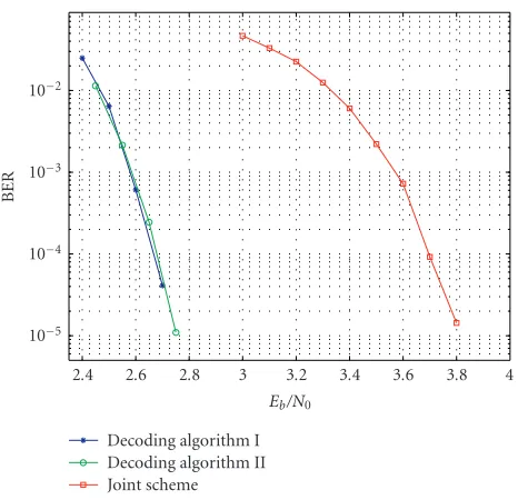
Figure6: Performance of the joint scheme and of the decoding al-gorithms I and II when the proposed concatenated system is uti-lized over AWGN channels. The overall rate of the code is 0.475. The Shannon limit for this case (assuming binary signaling) is
Eb/N0=0.08 dB.
still worse than that of decoding algorithms I and II, but it presents no oscillating behavior. This worse performance can be explained by the existence of some short cycles inGjoint,3
and by noticing that random connection assignments lead to a graph structure different from the specific one resulting from the concatenation of the inner and outer codes (repre-sented inFigure 3). This occurs because the graph inFigure 3
contains the outer coded bit nodes as additional variables that (due to the random connections) do not have equiva-lence inGjoint.
4 3.8 3.6 3.4 3.2 3 2.8 2.6 2.4
Eb/N0 10−5
10−4 10−3 10−2
BER
Decoding algorithm I Decoding algorithm II Joint scheme
Figure7: Performance of the joint scheme and of the decoding al-gorithms I and II when the proposed concatenated system is utilized over fully interleaved Rayleigh fading channels with perfect CSI at the receiver. The overall rate of the code (assuming binary signaling) is 0.475. The Shannon limit for this case isEb/N0=1.6 dB.
We also investigated the performance of LDGM codes over Rayleigh fading channels. We assume that the received sequence can be expressed asrk=ckyk+nk, where{yk}is the
binary transmitted sequence,{nk}is a set of statistically
in-dependent Gaussian random variables with zero-mean, and {ck}is modeled as a Rayleigh process. We also assume an
ide-ally interleaved channel, so that the sequence{ck}is uncor-related in timek, and perfect channel side information (CSI) is available at the decoder (i.e., the value of ck is known).
Figure 7shows the performance of the concatenated LDGM code defined before in this Rayleigh fading environment. No-tice that similar to the BSC and AWGN channels, no error floor appears here and decoding algorithms I and II outper-form the “joint” scheme,Gjointagain. The theoretical limit in this case (assuming binary signaling) isEb/N0=1.6 dB [30],
and both schedules I and II achieve a performance within 1.3 dB from this limit.
5. SOURCE AND JOINT SOURCE-CHANNEL CODING OF CORRELATED SOURCES: THEORETICAL LIMITS
Figure 8illustrates the system proposed in this paper for joint source-channel coding of correlated sources. For simplicity, we consider only two sources, but the approach can be easily extended to the case of more sources. The two sources are en-coded independently from each other (i.e., for a given source neither the realization from the other source nor the correla-tion model are available at the encoder site) and transmitted through two different noisy channels to a common decoder. Since the correlation between the sources is exploited at the
H(U1,U2) Source 1
Source 2
Encoder 1
Encoder 2 R1
R2
Channel 1
Channel 2
Joint decoder
U1
U2
Figure8: Proposed system for joint source-channel coding of cor-related sources. Each source is encoded independently and trans-mitted through a different noisy channel.
common receiver, the value of Eb/N0 corresponding to the
theoretical limit will be less than if the sources were inde-pendent. In this section, we review the theoretical limits for the case in which both channels are either noisy or noiseless (which corresponds to the case of compression of correlated sources).
5.1. Compression of correlated sources: Slepian-Wolf limit
It is well known [33, 34] that two jointly ergodic sources (U1,U2), defined over countably infinite alphabets, can be
compressed at rates (R1,R2), provided that
R1≥H
U1U2,
R2≥H
U2U1,
R1+R2≥H
U1,U2.
(4)
As explained before, compression is performed indepen-dently for each source and the decoder jointly acts over the compressed versions of the sources to recover the original se-quences.
5.2. Transmission of correlated sources over independent noisy channels
It has been recently shown [17,18] that the separation princi-ple between source and channel coding applies to the case of transmission of correlated sources over separated noisy chan-nels. In other words, the theoretical limit for the transmis-sion of two sources generating i.i.d. random pairs can be ob-tained by performing first distributed data compression up to the Slepian-Wolf limit followed by channel coding. There-fore, assuming that both sources are encoded at the same rate (R1=R2=R/2), the theoretical limit in communications for
a fixed transmission rate ofR/2information bits/channel use would then be achieved for each source when the two cor-related sources are first compressed up to the joint entropy (H(U1,U2)) and then a capacity achieving channel code of
rateRc = R/2 is used for each of them. By taking into ac-count that the energy per generated source bit (Eso) can be
related with the energy per information bit (Eb) by using the relation 2Eso=H(U1,U2)Eb, the theoretical limit forEso/N0
(for the case of two independent channels with capacityC) can be obtained by solving the equationR/2=C[18].
are met. On the one hand, optimum source coding for cor-related sources should be utilized. On the other, capacity achieving channel codes are necessary. The problem with this approach in practical systems is twofold. First, it is nec-essary to design good practical source codes for correlated sources. Moreover, in practical systems, errors introduced by the channel decoder could be catastrophic for the source de-coder. Besides, in our approach, it does not seem reasonable to first use LDGM codes to compress the sources and then some other LDGM codes to add redundancy, since the use of one LDGM code (per source) can perform the combined op-eration. In order to avoid these problems, we propose a joint source-channel coding scheme which in practical situations achieves performance very close to the theoretical limits. In our approach, each of the correlated binary sources is not source encoded, but directly channel encoded with a channel code of rate Rc. The information rate transmitted through the channel in this case isR1 =R2 =R/2=H(U1,U2)Rc/2
information bits/channel use. Notice that in order to keep the information rate per source (R/2), the code used in our joint source-channel coding approach (of rateRc) has to be less powerful than in the separate source and channel coding scheme (code of rateRc=R/2).
Specifically, the relation betweenRc andRc to keep the same information rate through the channel, R/2 = R
c, is
given byRc = H(U1,U2)R
c/2. The “weakness” of the code
in the joint source-channel coding approach will be compen-sated by exploiting the correlation between sources in the de-coder. Notice that the proposed joint source-channel coding approach allows a channel code of a single rate to be used in combination with sources having arbitrary joint entropy rates, with the modifications to maintain efficient coding in-volving only processing in the decoder.
6. TURBO-LIKE CODES FOR CORRELATED SOURCES: RATIONALE
As indicated in the introduction, compression (or joint source-channel coding) of multiterminal correlated sources can be seen as a problem of channel coding with side infor-mation. This is illustrated in Figure 9. To simplify the de-scription, we assume that the information from source 2 is perfectly available at the decoder and thatU1is the sequence
generated by source 1 that we want to compress. In order to do so,U1is encoded by a systematic channel encoder, so
that the nonsystematic coded bits, C1, constitute the
com-pressed sequence for source 1 (i.e., the systematic bits are eliminated). The decoder utilizes the compressed sequence for source 1 (O1=C1) plus the information proceeding from
the other source (U2). Notice that, because of the correlation
between sources, U2 can be used as a side information for
source 1. In fact, U2 can be thought as the corrupted
ver-sion of the systematic bits in source 1 whenU1is
transmit-ted through a channel model defined by the correlation be-tween sources. Therefore, recovery ofU1can be interpreted
as performing channel decoding over the corrupted version of U1 (U2) and the redundant/uncorrupted nonsystematic
Channel coding + systematic
symbols eliminated
Noiseless or noisy channel
Channel decoding
Noisy channel
p(y|x)
U1 C1 O1 U1
U2
Figure9: Source coding as a problem of channel coding with side information.U1is encoded by a systematic channel encoder, so that the nonsystematic bits,C1, constitute its compressed version.U2can be thought of as the corrupted version ofU1whenU1is transmit-ted through a channel model defined by the correlation between sources, and is used by the decoder together withO1 =C1to re-cover the original sequenceU1.
bitsO1 =C1proceeding fromU1. In the case in whichU2
were not perfectly available at the receiver, the decoder would consist of two blocks as the one shown inFigure 9(one for source 1 and the other for source 2). Then, decoding forU1
would use an estimate of U2as side information, and
pro-vide the resulting estimate ofU1as side information for the
decoding ofU2, with this process continuing iteratively. The
interpretation of joint source-channel coding of correlated sources as a problem of channel coding with side informa-tion is also straightforward. The only differences with respect to the case of pure source coding described above are: (i) se-quenceC1may include systematic bits, and (ii) sequenceC1
is corrupted by the channel noise, producing sequenceO1,
which is available at the decoder.
Turbo-like codes are very well suited to be applied in the context described in Figure 9. The reason is two fold. First, they are pseudorandom codes, and therefore adequate to achieve the theoretical limits corresponding to random codes (by using one turbo-like code as encoder for each of the correlated sources). Second, turbo-like codes are very well prepared to exploit side information. In order to do so, the known probabilistic description of the different sequences available at the decoder can be easily incorporated in the de-coding process, which will be (in general) represented by a graph. Moreover, even if the correlation model is not avail-able at the decoder, it is still possible to estimate it jointly with the decoding process (in many occasions with little per-formance degradation). Sections7and8develop these ideas for the case of LDGM codes. Although the simulation results presented there focus on the case of joint source-channel coding, the particularization of the proposed schemes for the case of pure source coding results in performances very close to the Slepian-Wolf limit [16].
7. LDGM CODES FOR CORRELATED SOURCES: PROPOSED SYSTEM
c1,out
c1,in
c2,out
c2,in u1
u2
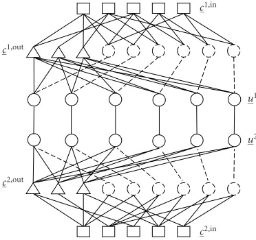
Figure10: Graph representing the joint source-channel decoder for transmission of correlated sources over separated noisy channels.
it may be advantageous in practical applications to use a joint source-channel coding approach, such as the one pre-sented in this paper and shown inFigure 8[35,36]. This ap-proach can be particularized into some special cases such as source coding of a single source (by ignoring the other source and considering noiseless channels), distributed source cod-ing (by considercod-ing noiseless channels) [37,38], and joint source-channel coding of single sources (by ignoring the other source).
For the development contained in this paper, we denote the two correlated binary information sequences as U1 =
u1
1u12. . .andU2 =u21u22. . .withukj ∈ {0, 1}. The correlation
model is established by first generating the symmetric i.i.d. sequenceU1(P(u1
k =0)=P(u1k =1)=1/2). Then, the
se-quenceU2is defined asu2
k=u1k⊕ek, where⊕indicates mod-ulus 2 addition andekis a random variable which takes value 1 with probabilitypand value 0 with probability 1−p. Each source is independently encoded with a system composed of a serial concatenation of two LDGM codes.4 For source j,
the coded bits generated by the outer encoder,cj,out, and the information bits,uj, constitute the systematic bit nodes for the inner encoder, which further generates the inner coded bitscj,in. After encoding, the resulting bits are sent through
the corresponding noisy channel, and decoded in the com-mon receiver by applying the belief propagation algorithm over the graph representing both decoders, which is shown inFigure 10.
Several activation schedules can be utilized in the decod-ing process, and, since the graph presents cycles, they can lead to different performance. We consider the five different acti-vation schedules shown below, where each repetition consti-tutes one iteration. Notation is consistent with the channel coding case explained inSection 3.
4The use of a single LDGM code results in intolerable error floors.
(i) Schedule 1 (flooding): repeat
u1,c1,in,c1,out,u2,c2,in,c2,out.
(ii) Schedule 2: repeat
u1,c1,in,c1,out,c1,in,c1,out,u1,
u2,c2,in,c2,out,c2,in,c2,out,u2.
(iii) Schedule 3: repeat
u1,c1,in,c1,out,u1,u2,c2,in,c2,out,u2.
(iv) Schedule 4: repeat
u1,c1,in,u1,c1,out,u1,u2,c2,in,u2,c2,out,u2.
(v) Schedule 5 (see [35]):
c1,out,c2,out.
Repeatu1,c1,in,u2,c2,in.
Repeatu1,c1,out,u2,c2,out, without exchanging information betweenu1andu2.
8. SIMULATION RESULTS FOR JOINT SOURCE-CHANNEL CODING OF CORRELATED SOURCES
In this section, we first analyze the performance of the five activation schedules introduced in last section when each source is independently channel encoded by the serial con-catenation of a (6.5,6.5)5 inner LDGM code and a regular
(4, 76) outer LDGM code (i.e., overall rateRc =0.475) and transmitted through a noisy channel. The length of the in-formation sequences is assumed to beL=9500 and the cor-relation parameter is fixed to p = 0.1.Figure 11shows the BER versusEso/N0when AWGN channels are considered. For
schedules 1 to 4, no errors were observed atEso/N0= −0.7 dB
after simulating more than 10 000 blocks. Since the theoret-ical limit in this case corresponds toEso/N0= −1.85 dB, the
proposed system is within 1.15 dB from this limit. Similar re-sults for the case of ideally interleaved Rayleigh fading chan-nels with perfect CSI at the receiver are shown inFigure 12. In this case, the gap with respect to the theoretical limit is around 1.5 dB. Notice that, for both figures, schedules 1 to 4 have very similar performances and their curves basically overlap. For schedule 5, which decodes first the inner code and then tries to eliminate the error floor with the outer code (without further exchange of information between the outer and the inner codes), the gap from the theoretical limit is larger.
Table 1 shows the maximum, minimum, and average numbers of iterations required to achieve convergence at
−0.4
−0.5
−0.6
−0.7
−0.8
−0.9
Eso/N0 10−5
10−4 10−3 10−2
BER
Schedule 1 Schedule 2 Schedule 3
Schedule 4 Schedule 5
Figure11: For the proposed joint source-channel coding scheme consisting of the serial concatenation of a (6.5,6.5) inner and a (4,76) outer LDGM code (overall rateRc=0.475), performance of different activation schedules for correlation parameterp=0.1 and AWGN channels is presented. For schedules 1 to 4, no errors were observed atEso/N0 = −0.7 dB after simulating more than 10 000 blocks.
some values ofEso/N0in Figures11and12. Notice that each
iteration in schedule 2 corresponds roughly to two iterations in schedules 1, 3, and 4 (most of the complexity is produced in the activation of the coded bit nodes). Taking this into ac-count, we can observe that in average schedules 1 to 4 re-quire approximately the same number of iterations. Notice that the number of iterations required for schedule 5 are ob-tained at different values ofEso/N0than those of schedules 1
to 4, which means that the comparison between schedule 5 and the other schedules is not very significant.
In order to further assess the performance of the pro-posed system, we consider different values of the parame-ter p and study the system performance utilizing schedule 1. As before, the length of the information sequence is fixed to L = 9500. For different values of p, we use the same (4,76) outer LDGM code as before, but we consider dif-ferent inner codes in order to optimize performance. Sim-ulation results are presented in Table 2 for AWGN chan-nels and in Table 3 for ideally interleaved Rayleigh fading channels with perfect CSI at the receiver. In both cases, the optimum degree of the inner code decreases with param-eter p. For all different values of p, at a bit error rate of 10−5, the gap between the theoretical limit and the
pro-posed system is within 1.8 dB for the AWGN channel and within 2.2 dB for the Rayleigh fading channel. Notice that this gap increases when p gets smaller, which was already pointed out in previous related work [21, 25, 26]. The gain of the proposed system is evident if we realize that, when the source correlation is not exploited in the decod-ing process, the achievable theoretical limits forEso/N0are
1.1 1 0.9 0.8 0.7 0.6 0.5 0.4 0.3
Eso/N0 10−5
10−4 10−3 10−2
BER
Schedule 1 Schedule 2 Schedule 3
Schedule 4 Schedule 5
Figure12: For the proposed joint source-channel coding scheme consisting of the serial concatenation of a (6.5,6.5) inner and a (4,76) outer LDGM codes (overall rateRc =0.475), performance of different activation schedules for correlation parameterp=0.1 and ideally interleaved Rayleigh fading channels with perfect CSI at the receiver is presented.
0.08 dB and 1.6 dB for the AWGN and Rayleigh fading chan-nel, respectively. The proposed approach achieves a perfor-mance (in terms of convergence threshold) similar to the system proposed in [25,26] for joint source-channel coding of correlated sources over separated AWGN channels using turbo codes. Moreover, after simulating the same number of blocks as in [25, 26], no error floor could be observed here. As shown in the appendix, the use of LDGM codes instead of turbo codes leads to a lower decoding complex-ity.
9. CONCLUSION
Table1: Minimum, average, and maximum number of iterations required to achieve convergence for the schemes considered in Figures11
and12, consisting of the serial concatenation of a (6.5,6.5) inner and a (4,76) outer LDGM codes (overall rateRc=0.475).
Schedule 1 Schedule 2 Schedule 3 Schedule 4 Schedule 5
AWGN
Eso/N0(dB) −0.7 −0.7 −0.7 −0.7 −0.3
Min 18 11 18 15 37
Average 30.9 17.3 29.5 25.7 59.5
Max 77 59 97 75 97
Rayleigh
Eso/N0(dB) 0.8 0.8 0.8 0.8 1.1
Min 18 11 17 16 19
Average 27.8 15.7 26.3 23.4 29.0
Max 54 31 49 50 90
Table2: For AWGN channels and different correlation parame-ters p, theoretical limit forEso/N0in dB ([Eso/N0]l, taken in steps of 0.01 dB), value ofEso/N0 in dB for which the proposed system achieves a BER less than 10−5([E
so/N0]s), and gap (taken in steps of 0.05 dB) between the theoretical limit and the performance of the proposed system.
p [Eso/N0]l [Eso/N0]s Gap Inner code 0.2 −0.96 0.06 <1.00 (6.5,6.5) 0.1 −1.84 −0.69 <1.15 (6.5,6.5) 0.05 −2.56 −1.21 <1.35 (6.25,6.25) 0.025 −3.07 −1.57 <1.50 (6,6) 0.01 −3.47 −1.72 <1.75 (5.75,5.75)
APPENDIX
CODING COMPLEXITY: LDGM VERSUS TURBO CODES
The encoding of a systematic LDGM code involves compu-tation of the parity bits, each of which only depends on a fi-nite number of systematic bits. Hence, similar to turbo codes, LDGM codes are encodable in linear time. From now on we will focus on the comparison between the two in terms of decoding complexity.
Complexity per decoding iteration
Reference [39] provides a detailed analysis on the decoding complexity of turbo codes. The main result is that for a turbo code with constituent encoders having ratek/nandSstates, the total number of additions/subtractions (additions) and multiplications/divisions (multiplications) per information bit and per iteration are given by
(i) additions [turbo (S,n)]=4(3S+n−4), (i) multiplications [turbo (S,n)]=2(8S+ 2n+ 5). We now analyze the decoding complexity of an (X,Y) LDGM code by following the development in [5] and our definitions of Qxmk and Rxmk. Because of their lower com-plexity, we will disregard operations consisting of addi-tions/multiplications by constants (notice that [39] disre-gards table look ups and maximum operations). We proceed in two steps. First, we calculate the number of operations required in the processing of a coded bit node. Second, we
Table3: For ideally interleaved Rayleigh fading channels with per-fect CSI at the receiver and different correlation parametersp, the-oretical limit forEso/N0in dB ([Eso/N0]l, taken in steps of 0.01 dB), value ofEso/N0in dB for which the proposed system achieves a BER less than 10−5 ([E
so/N0]s) and gap (taken in steps of 0.05 dB) be-tween the theoretical limit and the performance of the proposed system.
p [Eso/N0]l [Eso/N0]s Gap Inner code
0.2 0.41 1.76 <1.35 (6.5,6.5)
0.1 −0.74 0.76 <1.50 (6.5,6.5) 0.05 −1.62 −0.02 <1.60 (6.25,6.25) 0.025 −2.23 −0.38 <1.85 (6,6) 0.01 −2.71 −0.51 <2.20 (5.75,5.75)
look at the complexity in an information bit node. The total number of operations per information bit and per iteration will be the sum of the operations required in all the coded bit nodes plus the operations performed in all the informa-tion bit nodes divided by the total number of informainforma-tion bit nodes.
In order to calculate the number of operations in each coded bit node, notice that in (2) and (3) in this paperR1mk= 1−R0
mk. Therefore, once (2) is calculated, (3) can be obtained
without any additional complexity. Following the notation in [5], we defineδQmk =Q0
mk−Q1mk =1−2Q1mk. We also
defineDm =(−1)cmk∈L(m)δQmk. Then, (49) in [5] can be calculated as δrmk = Dm/(1−2Q1mk). In this way, since as
indicated in [5]r0mk=(1 +δrmk)/2 andr1
mk =(1−δrmk)/2,
(2) in this paper can be expressed as
R0 mk=
1−γm1+Dm/
1−2Q1 mk
2 +γm
1−Dm/1−2Q1mk
2
=1 2+
Dm1−2γm
21−2Q1mk, k=1· · ·Y.
(A.1)
In order to calculateR0mk, we first calculateDm, which re-quiresY−1 multiplications. Then, we utilize one more mul-tiplication to obtainDm(1−2γm), and finally we calculate
R0
Therefore, we just need 2Ymultiplications to perform all the processing required in a coded bit node. Since there are a to-tal ofN(1−Rc) coded bit nodes andNRcinformation bits (whereRc =Y/(X+Y) as indicated in this paper), the total amount of processing in the coded bits divided by the num-ber of information bits is 2Y(1−Rc)/Rc = 2X
multiplica-tions.
In order to calculate the number of operations performed in an information bit node, we follow (50)–(53) in [5]. Notice that Q0mk = αmkQ0k/R0mk, m = 1· · ·X. By forcing
Q0
mk +Q1mk = 1,Qmk0 can be calculated as Q0mk = 1/(1 +
(Q1
k/Qk0)(R0mk/(1−R0mk))). Therefore, after calculatingαkQ0k
and αkQ1k, which requires 2X multiplications, and Q1k/Q0k,
which requires another multiplication, the calculation ofQmk0 for a fixedm(counting an inversion as a multiplication) can be performed with 2 divisions. Therefore, the total number of operations to calculate allQ0
mk,m=1· · ·X, is 4X+1
mul-tiplications/divisions. SinceQ1mk = 1−Q0mk, no additional operations are required in an information bit node. Hence, the number of operations per information bit and per itera-tion in an (X,Y) LDGM code is as follows
(i) additions [LDGM (X,Y)]=0,
(ii) multiplications [LDGM (X,Y)]=2X+4X+1=6X+1. For instance, a (6,6) LDGM code performs 37 multipli-cations per information bit and per iteration, while a serial concatenated LDGM scheme with codes (6,6) and (4,76) forms 62 multiplications. A turbo code with comparable per-formance (S =8 andn=2) requires 88 additions and 146 multiplications (plus the table look ups and maximum oper-ations which are disregarded).
Total number of decoding iterations
The total number of iterations required for convergence can-not be predicted through analysis.Table 1in this paper shows the number of iterations required to achieve convergence for different activation schedules of the concatenated LDGM scheme in the case of joint source-channel coding. This num-ber is greater than the one usually required in turbo cod-ing schemes, but it is not enough to compensate the ad-vantage of LDGM codes in each iteration. Compensation does not occur in the channel coding case either. For in-stance, for the concatenated scheme used over AWGN chan-nels ([(6,6)(4,76)] with block size 20 000), the average num-ber of iterations at an Eb/N0 of 0.8 dB above the Shannon
limit is 21.7, which is about twice the number of iterations required in a comparable turbo code.
DISCLAIMER
The views and conclusions contained in this document are those of the authors and should not be interpreted as rep-resenting the official policies, either expressed or implied, of the Army Research Laboratory or the US Government.
ACKNOWLEDGMENT
The material in this paper was presented in part at Asilomar ’02 and ICIP ’03.
REFERENCES
[1] C. Berrou, A. Glavieux, and P. Thitimajshima, “Near Shannon limit error-correcting coding and decoding: Turbo-codes. 1,” inProc. IEEE International Communications Conference (ICC ’93), vol. 2, pp. 1064–1070, Geneva, Switzerland, May 1993. [2] R. G. Gallager, “Low-density parity-check codes,”IEEE Trans.
Inform. Theory, vol. 8, no. 1, pp. 21–28, 1962.
[3] R. G. Gallager, Low-Density Parity-Check Codes, MIT Press, Cambridge, Mass, USA, 1963.
[4] D. J. C. MacKay and R. M. Neal, “Near Shannon limit perfor-mance of low density parity check codes,” Electronic Letters, vol. 33, no. 6, pp. 457–458, 1997.
[5] D. J. C. MacKay, “Good error-correcting codes based on very sparse matrices,” IEEE Trans. Inform. Theory, vol. 45, no. 2, pp. 399–431, 1999.
[6] J.-F. Cheng and R. J. McEliece, “Some high-rate near capacity codecs for the Gaussian channel,” inProc. 34th Annual Aller-ton Conference on Communications, Control and Computing, Allerton, Ill, USA, October 1996.
[7] T. R. Oenning and J. Moon, “A low-density generator matrix interpretation of parallel concatenated single bit parity codes,” IEEE Trans. Magn., vol. 37, no. 2, pp. 737–741, 2001. [8] L. Ping, S. Chan, and K. L. Yeung, “Iterative decoding of
multi-dimensional concatenated single parity check codes,” inProc. IEEE International Communications Conference (ICC ’98), vol. 1, pp. 131–135, Atlanta, Ga, USA, June 1998. [9] S. S. Pradhan, J. Kusuma, and K. Ramchandran, “Distributed
compression in a dense microsensor network,” IEEE Signal Processing Mag., vol. 19, no. 2, pp. 51–60, 2002.
[10] S. Shamai (Shitz), S. Verdu, and R. Zamir, “Systematic lossy source/channel coding,” IEEE Trans. Inform. Theory, vol. 44, no. 2, pp. 564–579, 1998.
[11] A. D. Wyner, “Recent results in the Shannon theory,” IEEE Trans. Inform. Theory, vol. 20, no. 1, pp. 2–10, 1974.
[12] S. S. Pradhan and K. Ramchandran, “Distributed source cod-ing uscod-ing syndromes (DISCUS): design and construction,” in Proc. IEEE Data Compression Conference (DCC ’99), pp. 158– 167, Snowbird, Utah, USA, March 1999.
[13] S. S. Pradhan and K. Ramchandran, “Distributed source cod-ing: symmetric rates and applications to sensor networks,” in Proc. IEEE Data Compression Conference (DCC ’00), pp. 363– 372, Snowbird, Utah, USA, March 2000.
[14] S. S. Pradhan, K. Ramchandran, and R. Koetter, “A construc-tive approach to distributed source coding with symmetric rates,” inProc. IEEE International Symposium on Information Theory (ISIT ’00), p. 178, Piscataway, NJ, USA, June 2000. [15] J. Garcia-Frias and Y. Zhao, “Data compression of unknown
single and correlated binary sources using punctured turbo codes,” inProc. 39th Annual Allerton Conference on Commu-nication, Control, and Computing, Allerton, Ill, USA, October 2001.
[16] J. Garcia-Frias and Y. Zhao, “Compression of correlated bi-nary sources using turbo codes,”IEEE Commun. Lett., vol. 5, no. 10, pp. 417–419, 2001.
[17] J. Barros and S. D. Servetto, “On the capacity of the reachback channel in wireless sensor networks,” inProc. IEEE Workshop on Multimedia Signal Processing (Special) Session on “Signal Processing for Wireless Networks”, St. Thomas, Virgin Islands, USA, December 2002.
[19] Q. Zhao and M. Effros, “Lossless and near-lossless source cod-ing for multiple access networks,”IEEE Trans. Inform. Theory, vol. 49, no. 1, pp. 112–128, 2003.
[20] P. Mitran and J. Bajcsy, “Turbo source coding: a noise-robust approach to data compression,” inProc. IEEE Data Com-pression Conference (DCC ’02), p. 465, Snowbird, Utah, USA, April 2002.
[21] A. D. Liveris, Z. Xiong, and C. N. Georghiades, “Joint source-channel coding of binary sources with side information at the decoder using IRA codes,” inProc. IEEE Multimedia Signal Processing Workshop, pp. 53–56, St. Thomas, Virgin Islands, USA, December 2002.
[22] J. Garcia-Frias and J. D. Villasenor, “Combining hidden Markov source models and parallel concatenated codes,”IEEE Commun. Lett., vol. 1, no. 4, pp. 111–113, 1997.
[23] G.-C. Zhu and F. Alajaji, “Turbo codes for nonuniform mem-oryless sources over noisy channels,”IEEE Commun. Lett., vol. 6, no. 2, pp. 64–66, 2002.
[24] A. Aaron and B. Girod, “Compression with side informa-tion using turbo codes,” inProc. IEEE Data Compression Con-ference (DCC ’02), pp. 252–261, Snowbird, Utah, USA, April 2002.
[25] J. Garcia-Frias, “Joint source-channel decoding of correlated sources over noisy channels,” inProc. IEEE Data Compression Conference (DCC ’01), pp. 283–292, Snowbird, Utah, USA, March 2001.
[26] J. Garcia-Frias and Y. Zhao, “Near Shannon/Slepian-Wolf performance for unknown correlated sources over AWGN channels,” IEEE Trans. Comm., vol. 53, no. 4, pp. 555–559, 2005.
[27] J. Pearl,Probabilistic Reasoning in Intelligent Systems: Networks of Plausible Inference, Morgan Kaufmann, San Mateo, Calif, USA, 1988.
[28] F. R. Kschischang, B. J. Frey, and H.-A. Loeliger, “Factor graphs and the sum-product algorithm,”IEEE Trans. Inform. Theory, vol. 47, no. 2, pp. 498–519, 2001.
[29] J. Garcia-Frias and W. Zhong, “Approaching Shannon perfor-mance by iterative decoding of linear codes with low-density generator matrix,”IEEE Commun. Lett., vol. 7, no. 6, pp. 266– 268, 2003.
[30] S. G. Wilson, Digital Modulation and Coding, Prentice-Hall, Englewood Cliffs, NJ, USA, 1996.
[31] T. J. Richardson, M. A. Shokrollahi, and R. L. Urbanke, “De-sign of capacity-approaching irregular low-density parity-check codes,” IEEE Trans. Inform. Theory, vol. 47, no. 2, pp. 619–637, 2001.
[32] T. J. Richardson and R. L. Urbanke, “The capacity of low-density parity-check codes under message-passing decoding,” IEEE Trans. Inform. Theory, vol. 47, no. 2, pp. 599–618, 2001. [33] T. M. Cover, “A proof of the data compression theorem of
Slepian and Wolf for ergodic sources (Corresp.),”IEEE Trans. Inform. Theory, vol. 21, no. 2, pp. 226–228, 1975.
[34] D. Slepian and J. K. Wolf, “Noiseless coding of correlated in-formation sources,” IEEE Trans. Inform. Theory, vol. 19, no. 4, pp. 471–480, 1973.
[35] J. Garcia-Frias, W. Zhong, and Y. Zhao, “Iterative decod-ing schemes for source and channel coddecod-ing of correlated sources,” inProc. 36th Asilomar Conference on Signals, Sys-tems, and Computers (ASILOMAR ’02), Pacific Grove, Calif, USA, November 2002.
[36] W Zhong, H. Lou, and J. Garcia-Frias, “LDGM codes for joint source-channel coding of correlated sources,” inProc. ICIP’03, Barcelona, Spain, September 2003.
[37] T. Murayama, “Statistical mechanics of linear compres-sion codes in network communication,” Europhysics Letters, preprint, 2001.
[38] A. D. Liveris, Z. Xiong, and C. N. Georghiades, “Compression of binary sources with side information at the decoder using LDPC codes,” IEEE Commun. Lett., vol. 6, no. 10, pp. 440– 442, 2002.
[39] M. Y. Alias, F. Guo, S. X. Ng, T. H. Liew, and L. Hanzo, “LDPC and turbo coding assisted space-time block coded OFDM,” in Proc. IEEE Vehicular Technology Conference (VTC ’03), vol. 4, pp. 2309–2313, Jeju, Korea, April 2003.
Wei Zhongreceived the B.S. degree in elec-tronic engineering from Shanghai Jiao Tong University, Shanghai, China, in 2001. He is currently working towards the Ph.D. de-gree at the University of Delaware, USA. His research interests are in communications, turbo codes, joint source-channel coding, and coding for multiterminal sources.
Javier Garcia-Friasreceived the Ingeniero de Telecomunicaci ´on degree from Universi-dad Politecnica de Madrid, Spain, in 1992, the Licenciado en Ciencias Matematicas de-gree from UNED, Madrid, in 1995, and the Ph.D. degree in electrical engineering from UCLA, in 1999. In 1992 and from 1994 to 1996, he was with Telefonica I + D in Madrid. From September 1999 to August 2003, he was an Assistant Professor in the