555-233-118
Comcode 108678657
Issue 1
April 2000
Release 8.2
Printed in U.S.A. Notice
Every effort was made to ensure that the information in this book was complete and accurate at the time of printing. However, information is subject to change.
Your Responsibility for Your System’s Security
Toll fraud is the unauthorized use of your telecommunications system by an unauthorized party, for example, persons other than your com-pany’s employees, agents, subcontractors, or persons working on your company’s behalf. Note that there may be a risk of toll fraud associated with your telecommunications system and, if toll fraud occurs, it can result in substantial additional charges for your telecommunications services.
You and your system manager are responsible for the security of your system, such as programming and configuring your equipment to pre-vent unauthorized use. The system manager is also responsible for reading all installation, instruction, and system administration docu-ments provided with this product in order to fully understand the fea-tures that can introduce risk of toll fraud and the steps that can be taken to reduce that risk. Lucent Technologies does not warrant that this product is immune from or will prevent unauthorized use of com-mon-carrier telecommunication services or facilities accessed through or connected to it. Lucent Technologies will not be responsible for any charges that result from such unauthorized use.
Lucent Technologies Fraud Intervention
If you suspect that you are being victimized by toll fraud and you need technical support or assistance, call Technical Service Center Toll Fraud Intervention Hotline at 1 800 643-2353 or contact your local Lucent representative.
Federal Communications Commission Statement
Part 15: Class A Statement. This equipment has been tested and
found to comply with the limits for a Class A digital device, pursuant to Part 15 of the FCC Rules. These limits are designed to provide reason-able protection against harmful interference when the equipment is operated in a commercial environment. This equipment generates, uses, and can radiate radio-frequency energy and, if not installed and used in accordance with the instructions, may cause harmful interfer-ence to radio communications. Operation of this equipment in a resi-dential area is likely to cause harmful interference, in which case the user will be required to correct the interference at his own expense.
Part 68: Network Registration Number. This equipment is registered
with the FCC in accordance with Part 68 of the FCC Rules. It is identi-fied by FCC registration number AS593M-13283-MF-E. Refer to “Federal Communications Commission Statement” in “About This Book” for more information regarding Part 68.
Canadian Department of Communications (DOC) Interference Information
This digital apparatus does not exceed the Class A limits for radio noise emissions set out in the radio interference regulations of the Canadian Department of Communications.
Le Présent Appareil Nomérique n’émet pas de bruits radioélectriques dépassant les limites applicables aux appareils numériques de la class A préscrites dans le reglement sur le brouillage radioélectrique édicté par le ministére des Communications du Canada.
Ordering Information
Call: Lucent Technologies Publications Center
Voice 1 800 457-1235 International Voice 317 361-5353 Fax 1 800 457-1764 International Fax 317 361-5355
Write: Lucent Technologies Publications Center P.O. Box 4100
Crawfordsville, IN 47933 USA
Order: Document No. 555-233-118 Comcode 108678657 Issue 1, April 2000
For additional documents, refer to the section in “About This Book” entitled “Related Documents.”
You can be placed on a standing order list for this and other documents you may need. Standing order will enable you to automatically receive updated versions of individual documents or document sets, billed to account information that you provide. For more information on stand-ing orders, or to be put on a list to receive future issues of this docu-ment, contact the Lucent Technologies Publications Center.
European Union Declaration of Conformity
The “CE” mark affixed to the DEFINITY® equipment described in this book indicates that the equipment conforms to the following Euro-pean Union (EU) Directives:
• Electromagnetic Compatibility (89/336/EEC) • Low Voltage (73/23/EEC)
• Telecommunications Terminal Equipment (TTE) i-CTR3 BRI and i-CTR4 PRI
For more information on standards compliance, contact your local dis-tributor.
Comments
To comment on this document, return the comment card at the front of the document.
Acknowledgment
Contents
Contents iii
What’s New in Release 8.2csi xi
Features xi
Hardware xiii
Tools xiv
Commands, screens, and fields xv
Procedures xv
Upgrade tips xvi
Cautions and warnings xvi
Product names xvi
About This Book xvii
■ Conventions Used in This Book xvii
■ Related Documents xviii
■ How to Order Documentation xix
■ How to Comment on This Book xix
■ Where to Call for Technical Support xix
■ Security Issues xx
■ Trademarks xx
■ Standards Compliance xxi
■ Electromagnetic Compatibility Standards xxii
■ Antistatic Protection xxiii
■ Remove/Install Circuit Packs xxiii
■ Federal Communications Commission Statement xxiv
Part 68: Statement xxiv
1
Installing and Cabling the Cabinets 1-1■ Check Customer’s Order 1-1
■ Correcting Shipping Errors 1-1
■ Unpack and Inspect 1-1
■ Comcodes for CMC 1-3
■ Install the System Cabinets 1-6
Set the Carrier Address ID — All Cabinets 1-6
Floor-Mount the Cabinet 1-7
Contents
iv
Install Cabinet A — Wall-Mount 1-9
Install Left and Right Panels — Wall-Mount 1-13
■ AC Power and Ground 1-14
Uninterruptible Power Supply 1-16
CMC Cabinet Power Switch 1-17
Connect Cabinet Grounds and Other Grounds 1-18
Install Coupled Bonding Conductor 1-20
Connect and Route Cabinet AC Power Cords 1-20
■ Cable the System 1-22
Install Processor Interface Cable — Cabinet A
Only and TDM/LAN Bus Terminator 1-22
Cable the Multi-Cabinet System — Wall-Mount 1-23
■ Install Main Distribution Frame and External Modem 1-25
Install the MDF 1-25
Install the External Modem 1-30
■ Install Equipment Room Hardware 1-31
Cross-Connect the Cabinets to the MDF 1-31
Allowable Circuit Packs for CMC 1-31
Circuit Pack Installation 1-33
Off-Premises Circuit Protection 1-38
Install Sneak Fuse Panels 1-39
Label the Main Distribution Frame 1-42
■ Set Up System Access 1-43
Installing and using DSA 1-43
Connecting a PC 1-46
■ Set Ringing Option 1-53
■ Activate and Administer the System 1-54
Power Up System 1-54
System Administration 1-54
■ Install and Wire Telephones and Other Equipment 1-64 Install Attendant Console — Optional 1-75 Install 26B1 Selector Console — Optional 1-75
■ Connect External Alarms and Auxiliary Connections 1-76
■ Telephone Pin Designations 1-77
■ CAMA/E911 Installation 1-78
Hardware Setup 1-78
Administration Setup 1-78
■ Install the BRI Terminating Resistor 1-86
Terminating Resistor Adapter 1-87
Closet Mounted (110RA1-12) 1-88
■ Install Multi-point Adapters 1-90
BR851-B Adapter (T-Adapter) 1-90
367A Adapter 1-91
Basic Multi-point Installation Distances 1-92
■ Install Off-Premises Station Wiring 1-93
■ Install Emergency Transfer Unit and
Associated Telephones 1-98
Install the Emergency Transfer Panel 1-99
■ Connect Modem to Telephone Network 1-106
External Modem Option Settings 1-107
2
Completing Installation and Cable Pinouts 2-1■ Perform System Administration 2-1
■ Set Neon Voltage — Ring Ping 2-3
■ Installation Completion 2-4
■ Power Supply LED Indications 2-4
■ TN760D Tie Trunk Option Settings 2-5
■ TN464E/F Option Settings 2-7
■ Connector and Cable Diagrams — Pinout Charts 2-9
Processor Interface Cable Pinout 2-11
3
Upgrading R6csi/R7csi to R8csi 3-1■ Task Table 3-2
■ Read This First 3-2
■ Upgrade to Release 8 3-5
Check SPE 3-5
Check Link Status 3-5
Disable TTI 3-5
Disable Scheduled Maintenance and Alarm
Origination to INADS 3-5
Check TTI Status 3-6
Save Translations 3-6
Contents
vi
Verify Software Version 3-7
Shut Down DEFINITY AUDIX System (if necessary) 3-7 Install Circuit Pack (if necessary) 3-7
Upgrade Software 3-8
Complete Upgrade 3-8
Display Memory-Configuration 3-8
Administer the System 3-9
Enable TTI 3-12
Resolve Alarms 3-12
Check Link Status 3-12
Enable Scheduled Maintenance 3-12
Resolve Alarms 3-12
Enable Customer Options and Alarm Origination 3-13
Save Translations 3-13
Restore Announcements (if necessary) 3-13
Power Up DEFINITY AUDIX System 3-13
Return Equipment 3-14
■ DEFINITY AUDIX Power Procedures 3-14
4
Adding or Removing Hardware 4-1■ Add Circuit Packs 4-1
■ Add CO, FX, WATS, and PCOL 4-2
Requirements 4-2
Installation 4-2
■ Add DID Trunks 4-2
Requirements 4-2
Installation 4-2
■ Add Tie Trunks 4-3
Requirements 4-3
Installation 4-3
■ Add DS1 Tie and OPS 4-5
Service Interruption 4-5
■ Add Speech Synthesis 4-5
■ Add Code Calling Access 4-5
■ Add Pooled Modem 4-6
Settings for Modem Connected to the Data
Terminal Equipment (DTE) 4-7
■ Add Multiple Integrated Recorded Announcement 4-7 Save and Restore Recorded Announcements 4-8
■ Add ISDN — PRI 4-10
North American 4-10
International 4-10
Add Packet Bus Support 4-10
Add Circuit Packs 4-10
Install Cables 4-11
Enter Added Translations 4-11
Resolve Alarms 4-11
Save Translations 4-11
■ Add Packet Bus Support 4-11
Disable Alarm Origination 4-11
Save Translations 4-11
Install Circuit Packs 4-12
Administer the Bus Bridge 4-12
Test the Packet Bus and C-LAN Circuit Pack 4-12
Resolve Alarms 4-12
Enable Customer Options and Alarm Origination 4-12
■ Add CallVisor ASAI 4-13
Enter Added Translations 4-13
Save Translations 4-13
Add Packet Bus Support 4-14
Add Circuit Packs 4-14
Install Cables 4-14
Enter Added Translations 4-14
Resolve Alarms 4-14
Save Translations 4-14
■ Add DCS Interface 4-15
Add Circuit Packs 4-15
Administer the Bus Bridge 4-15
Test the Packet Bus and Control-LAN Circuit Pack 4-16
Install Cables 4-16
Contents
viii
Save Translations 4-17
■ Add ISDN—BRI 4-17
Add the Packet Bus Support 4-17
Add Circuit Packs 4-18
Install Cables 4-18
Enter Added Translations 4-18
Resolve Alarms 4-18
Save Translations 4-18
■ Add IP Interface Assembly 4-18
Installing in Media Processor Mode 4-19
Installing in IP Trunk Mode 4-30
Upgrading a TN802 V3 (or later) to a TN802B
(MedPro mode) 4-46
■ Add TTC Japanese 2-Mbit Trunks 4-51
Installing the trunk 4-51
■ Installing an Integrated Channel
Service Unit (ICSU) Module 4-51
Checking for required components 4-51
Installing the 120A CSU 4-52
■ Add NAA1 Fiber Optic Circuit Pack 4-55
Unpack and Inspect 4-55
Installation Instructions 4-56
Test the Installation of the ATM Circuit Pack 4-58
A
Troubleshooting an Upgrade A-1■ New for Release 8 A-2
Translation Copy Protection (TRANS-ID) A-2
Control LAN (C-LAN) A-2
System Links (SYS-LINK) A-3
■ Troubleshooting Guidelines A-3
■ Troubleshooting Release 8 Upgrades A-4
No Translation After Upgrade A-4
Translation Corruption Detected A-4
Re-install the ISDN-PRI Links (Only for Failed
Upgrades) A-5
B
Translation Copy Protection B-1■ Time Limit B-1 Restrictions During the Time Allotted B-1 Restrictions After the Time Allotted B-2
■ Alarm Resolution B-2
C
Access Security Gateway C-1■ Using the ASG Mobile C-1
GL
Glossary and Abbreviations GL-1Contents
What’s New in Release 8.2csi
This is a short list of what changed from Release 7csi. For more detailed information, refer to DEFINITY ECS Release 8 What’s New in Release 8. The categories addressed are as follows:
■ Features
■ Hardware
■ Tools
■ Commands, screens, and fields
■ Procedures
■ Upgrade tips
■ Cautions and warnings
■ Product names
Features
This list provides categorized features available with Release 8.2. For full descriptions, see DEFINITY Enterprise Communications Server Release 8, Issue 1.0 Change Description.
Phone features Networking — ISDN Public
64 bridged call appearances ATM circuit emulation service (CES)
Abort transfer Feature plus — non-DID calling via UDP
Automatic exclusion Restricted Presentation
Circular station hunting Multiple pubnet calling/connect numbers/system
Coverage of calls redirected off-net Pass advice of charge to BRI (basic rate interface) endpoints
Group call pick-up BellCore calling name ID
What’s New in Release 8.2csi
xii
Reset shift call Call-independent signaling connection (CISC) enhancements
Station self display VALU distinctive alerting
Call Center VALU call coverage
Advocate related enhancements Transfer to Audix
ASAI/computer telephony integration (CTI) enhancements
Coverage interaction support
Increased Call Center capacities (G3r) CAS Attendant display of COR
Site stats for ATM connected remote EPNs CAS Attendant return call
CMS measurement of ATM trunks CAS Display enhancements
CALLMASTER V (CC 6416D+) native support CAS Priority queue
PASTE update CAS RLT emulation via PRI
CentreVu computer Telephony on MAPD Green to Standard DEFINITY Wireless Business Systems
(DWBS)
13-digit authorization codes (red to std)
X-station mobility Networking — Other
Hospitality IP Solutions
Auto digit rotation for direct inward dial Interworking with bandwidth constricted ATM networks
Crisis alert to pager ATM - Hybrid reliability
Suite check-in via the hunt-to feature System availability/serviceability
International Optical drive
Administrable loss plan Restart notification
Brazil and Hungary — E&M signaling Reliability options
China — special dial tone C-LAN serviceability tools
China — time supervision & forced release Terminal support Japan — Support for Japan National Private
Networking
IDS (6200) family of analog terminals native support
Japan — Transfer Call Back 6400 tip/ring module
Brazil and Hungary — E&M signaling Fast analog modem support
Security Platform
DADMIN login 24-port analog line (TN793/TN2793B) with Caller ID
Hardware
Minimum required hardware
You need the following minimum required hardware to upgrade to Release 8.2csi software.
R8.2csi hardware
The following upgrade equipment is new to Release 8.2csi.
Equipment
Code
Comcode Notes
Basic processor cabinet J5889OT-1 —
Contains the following circuit packs:
■ TN798B (processor) ■ TN2182B (tone clock)
AC Power unit 650A
107949364
Equipment
Code
Comcode Notes
R8csi Generic Program Card (orange)
—
406805481 2-Mbyte translation flashcard
(white)
4-Mbyte translation flashcard (white)1
10-Mbyte translation flashcard (white)2
1. Required for systems using recorded announcements.
2. Required for systems with a DEFINITY ECS Wireless Business System installed.
—
601817448 —
601817422 —
601817430
Processor TN798B
108186255
What’s New in Release 8.2csi
xiv
Additional hardware available
The following equipment is port slot hardware introduced with Release 8.2csi.
Discontinued hardware
No equipment was discontinued with Release 8.2csi.
Tools
No new tools became available with Release 8.2csi.
Equipment
Code
Comcode Notes
DS1 interface TN2313
108382607
Cost reduction, no new features
Analog line TN793
103557468
24-port analog line with CID
Analog trunk/line combo TN797
103557500
Combines an analog trunk and line into one circuit pack.
Control-LAN (C-LAN) TN799B
108525528
Updates TN799; enables trace route command
IP interface assembly TN802B
108517996
Commands, screens, and fields
The following commands and screens are new to or affected by Release 8.2csi. The number of screens has changed, and some fields have moved to different screens.
Procedures
The following procedures and steps changed or were added because of problems identified in the laboratory or during early introduction.
Many of the upgrade procedures were reordered and the steps within the procedure better defined. Check the task tables at the beginning of each upgrade chapter for the current order.
Also, to reduce redundancy in the book, there is no longer a separate upgrade process for high or critical reliability. The procedures and steps that apply to high or critical reliability are noted where they occur in the upgrade process.
Command/field Screen Notes
reset translation-id System Parameters Security This command resets the translation-ID on the translation card to match the processor; saves translations to the memory card; and restores use of the add, change, remove, and duplicate commands.
Needs init login to correct TRANS-ID alarm.
Procedure Steps Notes
Check SPE 1. Type status system 1 and
press Enter to check the health of the system.
Becomes first step of upgrade procedure
Set Daylight Savings Rules
1. Type change
daylight-savings-rules
and press Enter.
What’s New in Release 8.2csi
xvi
Upgrade tips
The following upgrade tips were generated from problems identified in the laboratory or during early introduction.
■ Add Pooled Modem
— The pooled modem requires a Lucent WP90110 L7 power supply. Although integrated conversion can use either the L5 or L7, the combined only works with an L7.
Cautions and warnings
The following new cautions and warnings were generated from problems affecting possible data loss that were identified in the laboratory or during early introduction.
Product names
The following products have been renamed.
Procedure Caution or Warning
Add Pooled Modem
!
CAUTION:
The L5 and L7 power supplies look identical. Check the label to be sure you have the L7 before installing.
Product name Old name
IP Interface Assembly (TN802B)
About This Book
This document provides procedures to install, upgrade, or make additions to a DEFINITY® Enterprise Communications Server Release 8.2csi, using the Compact Modular Cabinet.
This document is intended for use by trained installation technicians.
Conventions Used in This Book
■ Information you type is shown as: save translation. To submit the
command you typed, press the Enter key in the numbers section of the keyboard, not the Enter/Return key in the letters section.
■ Information displayed on the management terminal is shown as: login ■ Keyboard keys are shown as: Enter.
■ Circuit pack codes (such as TN798B or TN2182B) are shown with the
minimum acceptable alphabetic suffix (like the ‘‘B” in TN2182B).
Generally, an alphabetic suffix higher than that shown is also acceptable. However, not every vintage of either the minimum suffix or a higher suffix code is necessarily acceptable.
NOTE:
About This Book
xviii Related Documents
The following conventions describe the systems referred to in this document.
■ The word system is a general term encompassing Release 8 and includes
references to the DEFINITY Enterprise Communications Server
■ Systems in this book are called Release 8, Release 8 CMC, and R8csi ■ Information in this book is applicable for Release 8 unless otherwise
specified
■ DEFINITY Enterprise Communications Server is abbreviated as DEFINITY
ECS
■ Physical dimensions in this book are in inches (in.) followed by metric
centimeters (cm) in parentheses. Wire gauge measurements are in AWG followed by the cross-sectional area in millimeters squared (mm2) in parentheses
Related Documents
As supplemental information, you may need the following documents when installing a DEFINITY ECS Release 8 system. These documents are available in English only unless otherwise noted.
■ DEFINITY Enterprise Communications Server Release 8 Administration for
Network Connectivity
■ BCS Products Security Handbook
■ DEFINITY Enterprise Communications Server Release 8 Installation for
Adjuncts and Peripherals
■ DEFINITY Enterprise Communications Server Release 8 Administrator’s
Guide
■ DEFINITY Enterprise Communications Server Release 8 Maintenance for
R8csi
■ DEFINITY Enterprise Communications Server Release 8 System
Description (available in other languages)
■ DEFINITY Communications System and System 75 and System 85
Terminals and Adjuncts
■ Switch Administration for DEFINITY AUDIX
■ DEFINITY Enterprise Communications Server Release 8 System ATM
Installation, Upgrades, and Administration
How to Order Documentation
A complete list of DEFINITY books is available in the Business Communications System Publications Catalog.
You can order this document and any other DEFINITY documentation directly from the Lucent Technologies Business Communications System Publications Fulfillment Center at 1-317-322-6791 or toll free within the United States at 1-800-457-1235.
How to Comment on This Book
Lucent Technologies welcomes your feedback. Please fill out the reader
comment card at the front of this book and return it. Your comments are of great value and help us to improve our documentation.
If the reader comment card is missing, fax your comments to 1-303-538-1741 or to your Lucent Technologies representative, and mention this document’s name and number, DEFINITY Enterprise Communication Server Release 8 Installation and Test for Compact Modular Cabinets, 555-233-118.
Where to Call for Technical Support
Telephone Number
DEFINITY Helpline (feature administration and system applications)
1-800-225-7585
Lucent Technologies Toll Fraud Intervention 1-800-643-2353
Lucent Technologies National Customer Care Center 1-800-242-2121
Lucent Technologies Corporate Security 1-800-822-9009
Streamlined Implementation (for missing equipment) 1-800-772-5409
USA/Canada Technical Service Center 1-800-248-1234
ITAC 1-303-804-3777
Lucent Technologies Centers of Excellence
Asia/Pacific Regional Support Center 65-872-8686
Western Europe/Middle East/South Africa 44-1252-77-4800
Central/Eastern Europe 361-345-4334
Central/Latin America Caribbean 1-303-804-3778
Australia 61-2-9352-9090
About This Book
xx Security Issues
Security Issues
To ensure the greatest security possible for customers, Lucent Technologies offers services that can reduce toll-fraud liabilities. Contact your Lucent Technologies representative for more security information.
Login security is an attribute of the DEFINITY ECS software. Existing passwords expire 24 hours after installation.
For Access Security Gateway (ASG), see Appendix C, ‘‘Access Security Gateway’’.
Trademarks
This document contains references to the following Lucent Technologies trademarked products:
■ ACCUNET®
■ AUDIX® ■ Callmaster® ■ CallVisor®
■ CONVERSANT®
■ DEFINITY®
■ FORUM™
■ MEGACOM®
■ TRANSTALK™
The following products are trademarked by their appropriate U.S. vendor:
■ LINX™ is a trademark of Illinois Tool Works, Incorporated
■ Shockwatch® is a registered trademark of Media Recovery, Incorporated ■ Styrofoam® is a registered trademark of Styrofoam Corporation
Standards Compliance
The equipment presented in this document complies with the following standards (as appropriate):
■ ITU-T (Formerly CCITT) ■ ECMA
■ ETSI ■ IPNS
■ DPNSS
■ National ISDN-1 ■ National ISDN-2 ■ ISO-9000 ■ ANSI
■ FCC Part 15 and Part 68
■ EN55022
■ EN50081
■ EN50082
■ CISPR22
■ Australia AS3548 (AS/NZ3548) ■ Australia AS3260
■ IEC 825 ■ IEC 950
■ UL 1459
■ UL 1950
■ CSA C222 Number 225
■ TS001
About This Book
xxii Electromagnetic Compatibility Standards
Electromagnetic Compatibility
Standards
This product complies with and conforms to the following standards (as appropriate):
■ Limits and Methods of Measurements of Radio Interference
Characteristics of Information Technology Equipment, EN55022 (CISPR22), 1993
■ EN50082-1, European Generic Immunity Standard ■ FCC Part 15
■ Australia AS3548
NOTE:
The system conforms to Class A (industrial) equipment. Voice terminals meet Class B requirements.
■ Electrostatic Discharge (ESD) IEC 1000-4-2 ■ Radiated radio frequency field IEC 1000-4-3 ■ Electrical Fast Transient IEC 1000-4-4 ■ Lightning effects IEC 1000-4-5
European Union Standards
Lucent Technologies Business Communications Systems (BCS) declares that the DEFINITY equipment specified in this document bearing the “CE” mark conforms to the European Union Electromagnetic Compatibility Directives.
The “CE” (Conformité Europeénne) mark indicates conformance to the European Union Electromagnetic Compatibility Directive (89/336/EEC), Low Voltage Directive (73/23/EEC), Telecommunication Terminal Equipment (TTE) Directive (91/263/EEC), i-CTR3 Basic Rate Interface (BRI), and i-CTR4 Primary Rate Interface (PRI) as applicable.
The “CE” mark is applied to the following Release 8 products:
■ Global AC-powered Multi-Carrier Cabinet (MCC)
■ DC-powered Multi-Carrier Cabinet (MCC) with 25 Hz ring generator ■ AC-powered Enhanced Single-Carrier Cabinet (ESCC) with 25 Hz ring
generator
■ AC-powered Compact Single-Carrier Cabinet (CSCC) with 25 Hz ring
generator
■ Enhanced DC power system
■ AC-powered Compact Modular Cabinet (CMC) with 25 Hz ring generator ■ AC-powered Compact Modular Cabinet (CMC) with 50 Hz ring generator
for France
Antistatic Protection
!
CAUTION:
When handling circuit packs or any components of a DEFINITY System, always wear an antistatic wrist ground strap. Connect the strap to an approved ground such as an unpainted metal surface on the DEFINITY System.
Remove/Install Circuit Packs
!
CAUTION:
About This Book
xxiv Federal Communications Commission Statement
Federal Communications Commission
Statement
Part 68: Statement
Part 68: Answer-Supervision Signaling. Allowing this equipment to be operated in a manner that does not provide proper answer-supervision signaling is in violation of Part 68 rules. This equipment returns answer-supervision signals to the public switched network when:
■ Answered by the called station ■ Answered by the attendant
■ Routed to a recorded announcement that can be administered by the CPE
user
This equipment returns answer-supervision signals on all DID calls forwarded back to the public switched telephone network. Permissible exceptions are:
■ A call is unanswered ■ A busy tone is received ■ A reorder tone is received
Lucent Technologies attests that this registered equipment is capable of providing users access to interstate providers of operator services through the use of access codes. Modification of this equipment by call aggregators to block access dialing codes is a violation of the Telephone Operator Consumers Act of 1990.
This equipment complies with Part 68 of the FCC Rules. A label is provided on this equipment that contains, among other information, the FCC registration number and ringer equivalence number (REN) for this equipment. If requested, this information must be provided to the telephone company.
The REN is used to determine the quantity of devices which may be connected to the telephone line. Excessive RENs on the telephone line may result in devices not ringing in response to an incoming call. In most, but not all areas, the sum of RENs should not exceed 5.0. To be certain of the number of devices that may be connected to a line, as determined by the total RENs, contact the local telephone company.
NOTE:
Means of Connection
Connection of this equipment to the telephone network is shown in the following table.
If the terminal equipment (DEFINITY® System) causes harm to the telephone network, the telephone company will notify you in advance that temporary discontinuance of service may be required. But if advance notice is not practical, the telephone company will notify the customer as soon as possible. Also, you will be advised of your right to file a complaint with the FCC if you believe it is necessary.
The telephone company may make changes in its facilities, equipment,
operations or procedures that could affect the operation of the equipment. If this happens, the telephone company will provide advance notice in order for you to make necessary modifications to maintain uninterrupted service.
If trouble is experienced with this equipment, for repair or warranty information, please contact the Technical Service Center at 1-800-242-2121. For assistance outside of the United States, refer to ‘‘Where to Call for Technical Support’’. If the equipment is causing harm to the telephone network, the telephone company may request that you disconnect the equipment until the problem is resolved.
It is recommended that repairs be performed by Lucent Technologies certified technicians.
The equipment cannot be used on public coin phone service provided by the telephone company. Connection to party line service is subject to state tariffs. Contact the state public utility commission, public service commission or corporation commission for information.
This equipment, if it uses a telephone receiver, is hearing aid compatible.
Manufacturer’s Port Identifier FIC Code
SOC/REN/
A.S. Code Network Jacks
Off/On Premises Station OL13C 9.0F RJ2GX, RJ21X, RJ11C
DID Trunk 02RV2-T 0.0B RJ2GX, RJ21X
CO Trunk 02GS2 0.3A RJ21X
CO Trunk 02LS2 0.3A RJ21X
Tie Trunk TL31M 9.0F RJ2GX
1.544 Digital Interface 04DU9-B,C 6.0P RJ48C, RJ48M
1.544 Digital Interface 04DU9-BN,KN 6.0P RJ48C, RJ48M
About This Book
1
Installing and Cabling the Cabinets
Check Customer’s Order
Check the customer’s order and the shipping packing lists to confirm that all equipment is present. If any equipment is missing, report this to your Lucent Technologies representative. Check the system adjuncts for damage and report all damage according to local shipping instructions.
Correcting Shipping Errors
1. Red-tag all defective equipment and over-shipped equipment and return according to the nearest Material Stocking Location (MSL) instructions. For international customers, contact your order service agent.
2. Direct all short-shipped reports to the nearest MSL. Contact the appropriate location for specific instructions. For Streamlined Implementation in the United States, call 1-800-772-5409.
Unpack and Inspect
READ THIS FIRST !
!
CAUTION:
A fully loaded system weighs 58 lbs (26.3 kg). Use lifting precautions. If the doors, power unit, and circuit packs are removed, the unit weighs only 29 lbs (13.1 kg).
Installing and Cabling the Cabinets
1-2 Unpack and Inspect
1
2. Equipment comcodes are listed in Table 1-1.
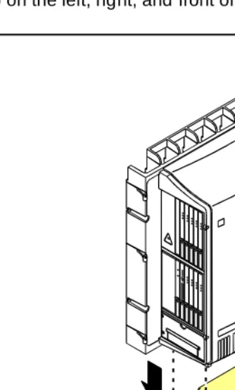
3. Before mounting the cabinets, remove the cabinet doors by opening them and lifting them straight up and off of the hinge pins.
Figure 1-1. Equipment Packed with the Compact Modular Cabinet Figure Notes
1. Left panel (also acts as a wall-mount template and as a floor mount pedestal)
2. Compact modular cabinet
3. Right panel
4. U.S. Robotics external modem (not shipped with all systems)
5. #12 x 1-inch shoulder screws
6. Processor interface cable (not shipped with all cabinets)
7. AC power cord (NEMA 5-15P or IEC 320)
8. Vertical TDM/LAN bus cable (not shipped with all systems)
9. Horizontal TDM/LAN bus cable (not shipped with all systems)
10. 14-in. (35.5 cm) 6 AWG (#40) (16 mm2) ground wire 11. Single-point ground block
qrdmpart KLC 011598
6
7
4
8
9
10 11
5 3
2
Comcodes for CMC
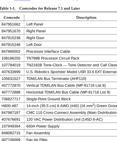
Table 1-1 lists the comcodes for equipment used with the CMC.
Table 1-1. Comcodes for Release 7.1 and Later
Comcode Description
847951662 Left Panel 847951670 Right Panel
847915238 Right Door
847915246 Left Door
847960002 Processor Interface Cable 108186255 TN798B Processor Circuit Pack
107784019 TN2182B Tone-Clock—Tone Detector and Call Classifier Circuit Pack 407633999 U.S. Robotics Sportster Model USR 33.6 EXT External Modem
105631527 TDM/LAN Bus Terminator (AHF110)
407772870 Vertical TDM/LAN Bus Cable (WP-91716 List 8) 407772888 Horizontal TDM/LAN Bus Cable (WP-91716 List 9) 706827717 Single-Point Ground Block
H600-487 14-inch (35.5 cm) 6 AWG (#40) (16 mm2) Green Ground Wire 847987187 CMC 110 Cross-Connect Assembly (Main Distribution Frame) 407676691 120 VAC Power Distribution Unit (145D 6-AC)
107949364 650A Power Supply
848082715 Fan Assembly
407745009 Fan Air Filter
405362641 120 VAC Power Cord (U.S.) 407786623 120 VAC Power Cord (Europe)
407786599 120 VAC Power Cord (United Kingdom) 407786631 120 VAC Power Cord (Australia)
407790591 120 VAC Power Cord (India)
106278062 Apparatus Blank (Circuit Pack Blank) (158P)
601817448 2-Mbyte Mass-Storage Translation Card (White Card)
Installing and Cabling the Cabinets
1-4 Comcodes for CMC
1
601817422 4-Mbyte Mass-Storage Translation Card (White Card) 601817430 10-Mbyte Mass-Storage Translation Card (White Card) 106606536 Integrated Channel Service Unit (ICSU) (120A2) 107988867 DS1 Loopback Jack (T1 Only) (700A)
107152969 75 Ohm DS1 Coaxial Adapter (888B) 403613003 157B Connecting Block
406948976 6SCP-110 Protector
107435091 507B Sneak Current Fuse Panel 407216316 220029 Sneak Current Fuse 403613003 157B Connecting Block
103970000 Main Distribution Frame Label (Code 220A)
104307327 C6C cable — 50-ft (15.2 m) shielded DS1 cable with 50-pin male to 15-pin male
104307376 C6D cable — 50-ft (15.2 m) shielded DS1 cable with 50-pin male on each end
104307434 C6E cable — 100-ft (30.5 m) shielded DS1 cable with 50-pin male to 50-pin female
104307475 C6F cable — 50-ft (15.2 m) shielded DS1 cable with 50-pin male to 3 in. (7.6 cm) stub
102381779 3B1A Carbon Block
104410147 3B1E-W Wide Gap Gas Tube
105514756 3C1S Solid State
102904893 4B1C Carbon Block with Heat Coil
104401856 4B1E-W Wide Gap Gas Tube with Heat Coil 104386545 4C1S Solid State with Heat Coil
406948976 SCP-110 Sneak Current Protector 407216316 220029 Fuse Sneak Current Protector 105581086 4C3S-75 Solid State with Heat Coil 406144907 ITW LINX Gas Tube, Avalanche Suppress 901007120 ITW Linx Ground Bar (used with above)
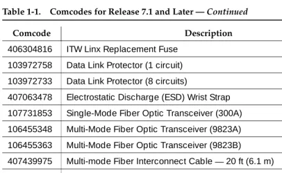
Table 1-1. Comcodes for Release 7.1 and Later — Continued
Comcode Description
406304816 ITW Linx Replacement Fuse 103972758 Data Link Protector (1 circuit) 103972733 Data Link Protector (8 circuits)
407063478 Electrostatic Discharge (ESD) Wrist Strap 107731853 Single-Mode Fiber Optic Transceiver (300A) 106455348 Multi-Mode Fiber Optic Transceiver (9823A) 106455363 Multi-Mode Fiber Optic Transceiver (9823B)
407439975 Multi-mode Fiber Interconnect Cable —20 ft (6.1 m) 407598325 Single-mode Fiber Interconnect Cable —20 ft (6.1 m) 105357727 Single-mode Fiber Optic Patch Cord —2 ft (0.6 m) 106060718 Single-mode 5-dB Attenuator
106060734 Single-mode 10-dB Attenuator
Table 1-1. Comcodes for Release 7.1 and Later — Continued
Comcode Description
Installing and Cabling the Cabinets
1-6 Install the System Cabinets
1
Install the System Cabinets
Set the Carrier Address ID — All Cabinets
Figure 1-2. Setting Carrier Address ID (Right Side)
1. Proceed to either ‘‘Floor-Mount the Cabinet’’ on page 1-7 or to ‘‘Wall-Mount the Cabinets’’ on page 1-8.
Figure Notes
1. Carrier A switch settings 2. Carrier B switch settings
3. Carrier C switch settings
OP
E
N
12
345
6
O
PEN
12
34
5
6
OP
E
N
12
3
4
5
6
swdmdip KLC 073198
OFF
1 2
Floor-Mount the Cabinet
The cabinet dimensions (with floor pedestal) are 28.5 in. (72.4 cm) high, 24.5 in. (62.2 cm) wide, and 12 in. (30.5 cm) deep. Maintain a service clearance of 12 in. (30.5 cm) on the left, right, and front of the cabinet.
Figure 1-3. Typical Floor Mount Installation
1. Proceed to ‘‘Cable the System’’ on page 1-22.
Figure Notes
1. Left panel (floor-mount pedestal) 2. #12 x 1-in. (2.5 cm) shoulder
screws
3. 12 in. (30.5 cm) minimum from nearest object (required to service the circuit packs)
indmflor KLC 110397
1
Installing and Cabling the Cabinets
1-8 Install the System Cabinets
1
Wall-Mount the Cabinets
!
CAUTION:
A fully loaded system weighs 58 lb (26.3 kg). Use lifting precautions. If the doors, power unit, and circuit packs are removed, the unit weighs only 29 lb (13.1 kg).
Install Plywood Backing onto Wall
The plywood and the hardware to mount the plywood are installer-provided.
NOTE:
The following plywood dimensions account for the extra space needed to install the panels on each side of the cabinet. The cabinet is 24 in. (0.6 m) wide and each panel is 12 in. (0.3 m) wide.
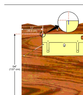
Single-Cabinet Installation
1. Install a 3/4-in. (2 cm) thick sheet of 2 x 4-ft (0.6 x 1.2 m) plywood horizontally onto the wall. See Figure 1-4.
The top of the plywood must be at least 54 in. (137 cm) from the floor.
2 or 3 Vertically Mounted Cabinets
1. Install a 3/4-in. (2 cm) thick sheet of 4 x 8-ft (1.2 x 2.4 m) plywood vertically onto the wall. See Figure 1-6.
2 Cabinets Vertically Mounted and 1 Cabinet Horizontally Mounted
1. Install a 3/4-in. (2 cm) thick sheet of 4 x 8-ft (1.2 x 2.4 m) plywood vertically onto the wall. See Figure 1-6.
Install Cabinet A — Wall-Mount
Figure 1-4. Left Panel Used as Mounting Template
1. Place the template on the wall ensuring that the top surface is level. 2. Mark two 1/8-in. (0.3 cm) pilot holes in the mounting hole locations. 3. Remove the template from the wall.
4. Drill the two pilot holes.
5. Thread two #12 x 1-in. shoulder screws partially into the holes.
Installing and Cabling the Cabinets
1-10 Install the System Cabinets
1
Figure 1-5. Typical Wall-Mount Installation
7. Drill two lower mounting holes using the cabinet as a template. 8. Thread the 2 lower screws and tighten.
!
CAUTION:
Be sure the right bottom safety screw is in place and tight.
Figure Notes
1. #12 x 1-in. shoulder screws 2. #12 x 1-inch safety screw indmins1 KLC 110397
FLOOR
A
Install 2 or 3 Vertically Mounted Cabinets
Figure 1-6. Typical Vertical Multicabinet Installation
1. Securely tighten the shoulder screws and safety screws.
Figure Notes
1. #12 x 1-inch shoulder screws 2. #12 x 1-inch safety screw Floor
indmins7 LJK 102197
5" (12.7 cm)
A
C B
48" (122 cm)
1
1 2
Installing and Cabling the Cabinets
1-12 Install the System Cabinets
1
Install 2 Cabinets Vertically and 1 Cabinet
Horizontally
Figure 1-7. Typical 3-Cabinet Installation
1. Securely tighten the shoulder screws and safety screws.
Figure Notes
1. #12 x 1-inch shoulder screws 2. #12 x 1-inch safety screw
3. Second sheet of plywood Floor
indmins9 LJK 102197
29 1/2" (75 cm)
54" (137 cm)
5" (12.7 cm) 96" (244 cm)
1
1 2
3 A
C
Install Left and Right Panels — Wall-Mount
Figure 1-8. Left and Right Panel Installation
1. Align the cutouts in the panels with the cabinet hinges.
2. Drill a 1/8-inch (0.3 cm) pilot hole into the wall and secure the panels with the #12 x 1-inch shoulder screws.
Figure Notes
1. Left panel 2. Right panel
Installing and Cabling the Cabinets
1-14 AC Power and Ground
1
AC Power and Ground
!
CAUTION:
The system requires a dedicated AC power circuit that is not shared with other equipment and is not controlled by a wall switch. The AC receptacle must not be located under the Main Distribution Frame and must be easily accessible.
!
CAUTION:
The latch only removes DC power from the cabinet. Unseating the power supply removes AC power from the power supply, but not from the cabinet. To remove AC power from the cabinet, pull the AC power cord from the AC appliance connector on the rear of the cabinet.
!
CAUTION:
System grounding must comply with the general rules for grounding provided in Article 250 of the National Electrical Code (NEC), National Fire Protection Agency (NFPA) 70, or the applicable electric code in the country of installation.
!
CAUTION:
AC mains wiring and testing must be performed by a qualified electrician and must conform to Article 250 of the National Electrical Code (NEC), National Fire Protection Agency (NFPA) 70, or the applicable electric code in the country of installation.
Check AC Power
Each CMC uses an auto-ranging 85 to 264 VAC power supply, 47 to 63 Hz, 330 W, 4.5 amps (100-120 VAC) or 2.3 amps (200 to 240 VAC), at 500 VA. The AC power source can be 1 phase of 120 VAC with neutral (100 VAC for Japan) with 15 amp circuit breaker, or 1 phase of 220 or 240 VAC (200 VAC for Japan) with 10 amp circuit breaker. The AC cord uses a NEMA 5-15P plug or an IEC 320 plug.
Before powering up the system, check the AC power in the equipment room using a KS-20599 digital voltmeter (DVM) (or equivalent).
1. Measure the AC voltage between the hot and neutral side of the receptacle.
2. Depending on the AC power source, verify that the meter reads 90 to 132 VAC or 180 to 264 VAC. If not, have a qualified electrician correct the problem.
3. Measure the voltage between the neutral and ground side of the receptacle.
4. Verify that the meter reads 0 VAC. If not, have a qualified electrician correct the problem.
Approved Grounds
An approved ground is the closest acceptable medium for grounding the building entrance protector, entrance cable shield, or single-point ground of electronic telephony equipment. If more than 1 type of approved ground is available on the premises, the grounds must be bonded together as required in Section 250-81 of the National Electrical Code.
Grounded Building Steel
—
The metal frame of the building where it is effectively grounded by 1 of the following grounds: acceptable metallic water pipe, concrete encased ground, or a ground ring.Acceptable Water Pipe
—
A metal underground water pipe, at least 1/2-in. (1.3 cm) in diameter, in direct contact with the earth for at least 10 ft (3 m). The pipe must be electrically continuous (or made electrically continuous by bonding around insulated joints, plastic pipe, or plastic water meters) to the point where the protector ground wire connects. A metallic underground water pipe must be supplemented by the metal frame of the building, a concrete-encased ground, or a ground ring. If these grounds are not available, the water pipe ground can be supplemented by 1 of the following types of grounds:■ Other local metal underground systems or structures
—
Localunderground structures such as tanks and piping systems
■ Rod and pipe electrodes
—
A 5/8-in. (1.6 cm) solid rod or 3/4-in. (2 cm)conduit or pipe electrode driven to a minimum depth of 8 ft (2.4 m)
■ Plate electrodes
—
Must have a minimum of 2 ft2 (0.185 m2) of metallicsurface exposed to the exterior soil
Concrete Encased Ground
—
An electrode encased by at least 2 in. (5.1 cm) of concrete and located within and near the bottom of a concrete foundation or footing in direct contact with the earth. The electrode must be at least 20 feet (6.1 m) of 1 or more steel reinforcing bars or rods 1/2-in. (1.3 cm) in diameter, or at least 20 ft (6.1 m) of bare, solid copper, 4 AWG (26 mm2) wire.Installing and Cabling the Cabinets
1-16 AC Power and Ground
1
APPROVED FLOOR GROUNDS
!
CAUTION:
If the approved ground is inside a dedicated equipment room, then these connections must be made by a qualified electrician.
Floor grounds are those grounds on each floor of a high-rise building that are suitable for connection to the ground terminal in the riser closet and to the cabinet single-point ground terminal. Approved floor grounds may include:
■ Building steel
■ The grounding conductor for the secondary side of the power transformer
feeding the floor
■ Metallic water pipes
■ Power-feed metallic conduit supplying panel boards on the floor ■ A grounding point specifically provided in the building for the purpose
Uninterruptible Power Supply
An optional UPS (Uninterruptible Power Supply) may be used for power holdover. The type of UPS depends on the holdover requirements. Holdover times vary from less than 10 minutes to up to 8 hours. The UPS must provide surge protection for all connected cabinets.
1. Connect the UPS to an electrical outlet capable of handling the power requirements of all cabinets:
a. For 100 VAC, multiply 4.5 Amps times the number of cabinets. b. For 120 VAC, multiply 3.8 Amps times the number of cabinets. c. For 200 VAC, multiply 2.3 Amps times the number of cabinets. d. For 220-240 VAC, multiply 2.0 Amps times the number of cabinets. 2. Be sure that Cabinet A (control carrier) is connected to an “unswitched” or
CMC Cabinet Power Switch
!
CAUTION:
The latch only removes DC power from the cabinet. Unseating the power supply removes AC power from the power supply, but not from the cabinet. To remove AC power from the cabinet, pull the AC power cord from the AC appliance connector on the rear of the cabinet. See Figure 1-9.
Figure 1-9. CMC Power Supply Figure Notes
1. Latch
psdmdc RPY 011998
Installing and Cabling the Cabinets
1-18 AC Power and Ground
1
Connect Cabinet Grounds and Other Grounds
The following additional grounding requirements must be met:
■ The approved ground wire must be green, 6 AWG (#40) (16 mm2),
copper, stranded wire (this is in addition to the ground wire in the AC power cord)
■ Bond all approved grounds at the single-point ground to form a single
grounding electrode system
Install the Ground Block
1. Mount the ground block as shown in Figure 1-10. 2. Make the cable connections as shown in Figure 1-11.
Figure 1-10. Ground Block Installation to Right Panel Figure Notes
1. #12 x 1-inch shoulder screws 2. Single-point ground block indmingb RPY 012398
1 2
2
Figure 1-11. Typical Cabinet Grounding Figure Notes
1. 6 AWG (#40) (16 mm2) cabinet ground wire
2. 6 AWG (#40) (16 mm2) ground wire to next cabinet
3. Single-point ground block
4. AC load center single-point ground 5. 10 AWG (#25) (6 mm2) wire to coupled
bonding conductor (CBC)
6. 6 AWG (#40) (16 mm2) ground wire from single-point ground block to the AC load center single-point ground
5
cadmgrd1 KLC 020698
4
2 1 1
1
3
Installing and Cabling the Cabinets
1-20 AC Power and Ground
1
Install Coupled Bonding Conductor
The Coupled Bonding Conductor (CBC) provides for mutual inductance coupling between the CBC and the telephone cables that are exposed to lightning. The conductor can be a 10 AWG (#25) (6 mm2) wire tie wrapped to the exposed cables, a metal cable shield around the exposed cables, or 6 spare pairs from the exposed cable.
In a high rise building, connect the CBC to an approved building ground on each floor. To provide the coupled bonding protection:
1. Connect 1 end of the conductor to a telephone cable building entrance protector ground that is connected to an approved ground.
2. Route the rest of the conductor next to the exposed telephone cables being protected until they reach the cross-connect nearest to the telephone system.
3. Position the non-exposed telephone cables at least 12 inches (30.5 cm) away from exposed telephone cables whenever possible.
4. Terminate the other end to the single-point ground block provided for the telephone system.
Connect and Route Cabinet AC Power Cords
!
CAUTION:
The AC power cords may connect to a properly rated power distribution unit, individual AC power receptacles, or to a UPS. See Figure 1-12.
1. Be sure the circuit breakers at the AC load center are OFF.
Figure 1-12. Routing AC Power Cords to a Power Distribution Unit Figure Notes
1. Cabinet AC power cord 2. Surge-protected AC power
distribution unit (120 VAC systems) (optional)
/,1( )$8/7 *5281'2. $/:$<6 21 32:(5 3527(&7,21
pcdm5cmc RPY 011998
1
1
Installing and Cabling the Cabinets
1-22 Cable the System
1
Cable the System
Install Processor Interface Cable — Cabinet A
Only and TDM/LAN Bus Terminator
Figure 1-13. System Cable Connections
1. Connect the Processor Interface Cable to slot 1 of Cabinet A. See Figure 1-13.
2. Install the TDM/LAN bus terminators.
Figure Notes
Cable the Multi-Cabinet System — Wall-Mount
Vertically Mounted System
1. Route the TDM/LAN bus cables through the cable trough. See Figure 1-14.
Figure 1-14. TDM/LAN Bus Cables and Terminators Figure Notes
1. TDM/LAN bus terminator (at each end of the TDM/LAN bus)
Installing and Cabling the Cabinets
1-24 Cable the System
1
Vertically and Horizontally Mounted System
Only 1 horizontal TDM/LAN Bus cable is allowed per system. See Figure 1-15. 1. Route the TDM/LAN bus cables through the cable trough.
Figure 1-15. System Cable Connections Figure Notes
1. TDM/LAN bus terminator (at each end of the TDM/LAN bus)
2. Vertical TDM/LAN bus cable (List 8)
3. Horizontal TDM/LAN bus cable (List 9)
Install Main Distribution Frame and
External Modem
Install the MDF
!
CAUTION:
The optional MDF is a special 110 cross-connect field and is smaller than standard 110 cross-connect hardware. Do not install standard 110 hardware inside the right panel.
NOTE:
The depth of any equipment installed inside the right panel must not exceed 2.5 inches (6.3 cm), otherwise the right cover panel cannot fit over the right panel.
The optional MDF represents the trunk/auxiliary field.
1. Mount the optional MDF to the right panel using one of the following:
■ For bottom-mount MDFs, refer to ‘‘Bottom-mounted MDF with Modem’’ on page 1-25.
■ For top-mount MDFs (in cabinets other than cabinet A),
refer to ‘‘Top-Mounted MDF’’ on page 1-27.
■ For dual-mount MDFs, refer to ‘‘Dual MDFs’’ on page 1-28.
Bottom-mounted MDF with Modem
1. On the rear of the MDF, cut the cable tie securing the top 5 cables to the MDF mounting frame.
2. Mount the MDF to the right panel. See Figure 1-16.
Installing and Cabling the Cabinets
1-26 Install Main Distribution Frame and External Modem
1
Figure 1-16. Typical Bottom-Mount MDF and Modem Cable Routing Figure Notes
1. Main distribution frame (MDF) 2. External modem
3. Processor interface cable (connect P2 to modem, connect J1 to cable 1 on MDF)
4. #12 x 1-inch shoulder screw cadmrpnl KLC 070698 1
1 2
5 6 7 8 4 3
9 10
3
1 2
4
10 10
9 9
8 8
7 7
6 6
5 5
4 4
3 3
2 2
Top-Mounted MDF
Use this configuration when the cabinet is wall-mounted, and is near the floor. Do not use this configuration for cabinet A.
Figure 1-17. Typical Top-Mount MDF Cable Routing
1. On the rear of the MDF, cut the cable tie securing the top 5 cables to the MDF mounting frame.
2. Mount the MDF to the right panel. See Figure 1-17.
3. Secure all 10 cables to the bottom left bracket on the MDF with a cable tie.
Figure Notes
1. Main distribution frame (MDF) 2. Connect cable 1 to slot 1
3. #12 x 1-inch shoulder screw cadmmdf2 KLC 070698
1 2
5 6 7 8 4 3
9 10
1
2
3
10 10
9 9
8 8
7 7
6 6
5 5
4 4
3 3
2 2
Installing and Cabling the Cabinets
1-28 Install Main Distribution Frame and External Modem
1
Dual MDFs
Use this configuration when mounting two MDFs.
Figure 1-18. Preliminary Dual-Mount MDF Cable Routing Figure Notes
1. Main distribution frame (MDF) 2. Connect cable 1 to slot 1
3. To external modem 2
cadmrpn2 KLC 070698 1
3
1 2
5 6 7 8 4 3
9 10
1
10 10
9 9
8 8
7 7
6 6
5 5
4 4
3 3
2 2
1. On the rear of the MDF, cut the cable tie securing the top 5 cables to the MDF mounting frame.
2. Mount the MDF to the bottom position on the right panel. See Figure 1-18. 3. Secure all 10 cables to the bottom left bracket on the MDF with a cable tie. 4. Mount the second MDF to the top position on the right panel. See
Figure 1-19.
Figure 1-19. Typical Dual-Mount MDF Cable Routing Figure Notes
1. Main distribution frame (MDF) 2. #12 x 1-inch shoulder screw cadmrpn3 LJK 050198
1 2
5 6 7 8 4 3
9 10
2
1 2
5 6 7 8 4 3
9 10
1
10 10
9 9
8 8
7 7
6 6
5 5
4 4
3 3
2 2
Installing and Cabling the Cabinets
1-30 Install Main Distribution Frame and External Modem
1
Install the External Modem
The U.S. Robotics Sportster Model USR 33.6 EXT external modem is the recommended external modem. Release 8 CMC systems operate with this modem set to the factory default settings.
NOTE:
You may use a locally obtained, type-approved external modem (33.6 kbps and V.34 protocol). Contact your Lucent Technologies representative for more information.
1. Use installer-provided hardware to mount the modem. See Figure 1-16. If top-mounting MDFs or dual-mounting MDFs, mount the external modem to the plywood in a location which allows the standard connection to the interconnect cable.
2. Route the MODEM cable (P2) from the Processor Interface Cable through the cable trough and to the modem.
3. Connect the cable to the modem. Refer to ‘‘Processor Interface Cable Pinout’’ on page 2-11 for the pinout of the modem cable.
4. Plug the modem power cord into an electrical outlet and turn on the modem.
Install Equipment Room Hardware
Refer to DEFINITY Communications System Generic 1 and Generic 3 Main Distribution Field Design, 555-230-630, for more information.
Cross-Connect the Cabinets to the MDF
1. Cross-connect the ports on the trunk and line circuit packs to the MDF as required. See Figure 1-21 on page 1-37.
Allowable Circuit Packs for CMC
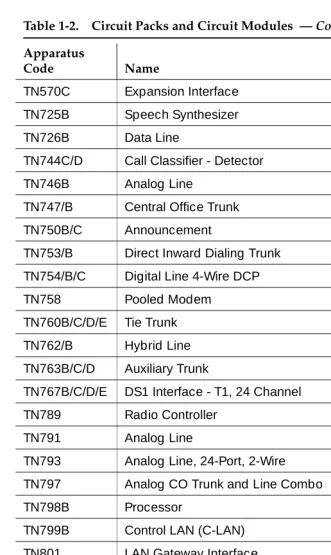
Table 1-2 lists the circuit packs that can be used with Release 8.
Table 1-2. Circuit Packs and Circuit Modules
Apparatus
Code Name
ED-1E568 (TN2169) (TN567)
DEFINITY AUDIX R3 System
ED-1E568 (TN2170)
CallVisor ASAI over the DEFINITY (LAN) Gateway R1
J58890M-1 (TN801)
CallVisor ASAI/Call Visor PC/LAN over the DEFINITY LAN Gateway R2
NAA1 Fiber Optic Cable Adapter Circuit Pack
TN429/B/C/D Analog Direct Inward/Outward Dialing (DIOD) Central Office Trunk
TN433 Voice Synthesizer
TN436B Direct Inward Dialing Trunk
TN439 Tie Trunk
TN459B Direct Inward Dialing Trunk
TN464F DS1 Interface - T1, 24 Channel - E1, 32 Channel
TN465C Central Office Trunk
TN497 Tie Trunk - Italy
TN556B/C/D ISDN-BRI 4-Wire S/T-NT Interface
TN568 Definity AUDIX Slim
Installing and Cabling the Cabinets
1-32 Install Equipment Room Hardware
1
TN570C Expansion Interface
TN725B Speech Synthesizer
TN726B Data Line
TN744C/D Call Classifier - Detector
TN746B Analog Line
TN747/B Central Office Trunk
TN750B/C Announcement
TN753/B Direct Inward Dialing Trunk
TN754/B/C Digital Line 4-Wire DCP
TN758 Pooled Modem
TN760B/C/D/E Tie Trunk
TN762/B Hybrid Line
TN763B/C/D Auxiliary Trunk
TN767B/C/D/E DS1 Interface - T1, 24 Channel
TN789 Radio Controller
TN791 Analog Line
TN793 Analog Line, 24-Port, 2-Wire
TN797 Analog CO Trunk and Line Combo
TN798B Processor
TN799B Control LAN (C-LAN)
TN801 LAN Gateway Interface
TN802B IP Interface Assembly
TN1654 DS1 Converter
TN2135 Analog Line
TN2140B Tie Trunk
TN2146 Direct Inward Dialing Trunk
TN2147C Central Office Trunk
TN2181 Digital Line - 16 ports, 2-Wire DCP
Table 1-2. Circuit Packs and Circuit Modules — Continued
Apparatus
Code Name
Circuit Pack Installation
!
CAUTION:
When handling circuit packs or any components of a DEFINITY System, always wear an authorized wrist ground strap. Connect the strap to the ground connector provided on the system cabinet.
NOTE:
Unlike previous releases of DEFINITY, the circuit pack slots in the CMC are not purple or white. This is because all of the circuit pack slots in the CMC are “universal slots.” That is, any slot can contain any type of port circuit pack.
TN2182/B Tone-Clock - Tone Detector and Call Classifier
TN2183 Analog Line
TN2184 DIOD Trunk
TN2185/B ISDN-BRI 4-Wire S/T-TE Interface (Trunk Side)
TN2198 ISDN-BRI 2-Wire U Interface
TN2199 Central Office Trunk
TN2214/B Digital Line, 24-Port, 2-Wire DCP - Category B TN2215 Analog Line, 16-Port 2-Wire - Category B TN2224/B Digital Line, 24-Port, 2-Wire DCP
TN2305 ATM Interface (Multimode)
TN2306 ATM Interface (Single-Mode)
TN2313 DS1 Interface
TN2464 DS1 Interface - T1, 24 Channel - E1, 32 Channel
TN2793/B Analog Line 24-Port
Table 1-2. Circuit Packs and Circuit Modules — Continued
Apparatus
Code Name
Installing and Cabling the Cabinets
1-34 Install Equipment Room Hardware
1
Circuit Pack Slot Loading
In general, load the circuit packs so that the number of packs in each cabinet is about equal and the trunks and lines are evenly distributed among the cabinets. See Figure 1-20.
1. Install the TN798B Processor circuit pack in slot 1 of Cabinet A. 2. Install the TN2182B Tone-Clock circuit pack in slot 2 of Cabinet A.
Load all port circuit packs starting with Cabinet A first, Cabinet B next, and so forth. Return to Cabinet A and repeat.
3. A TN744D Call Classifier/Tone Detector circuit pack may be required in systems with heavy traffic. Install the TN744D into any port slot. Slot 1 of Cabinet B is preferred.
Figure 1-20. Control Carrier Slot Layout Figure Notes
1. Line circuit pack slots 2. Trunk circuit pack slots
Table 1-3. Circuit Pack Installation Order (Loading)
Function Apparatus Code Load From Notes
Processor TN798B Slot 1 in Cabinet A
Tone Clock TN2182B Slot 2 in Cabinet A
Call Classifier/ Tone Detector
TN744D Slot 1 of Cabinet B
If slot is not available, load in first available slot from slot 1.
Continued on next page
scdmlft2 EWS 102798
MAJ MIN ON OFF
AMBER
CARD
IN
USE
RED
EM
ER
XFER
ON
EM
XFR
AUTO
T N 7 9 8 B
T N 2 1 8 2 B
5 10
1 6
Installing and Cabling the Cabinets
1-36 Install Equipment Room Hardware
1
1. Cross-connect the port circuit packs to the MDF. See Figure 1-21.
DEFINITY AUDIX ED-1E546 (TN566/TN567) Slots 6-9 TN566 and TN567 require 4 slots with overlap into area to the left of slot 6. In any other position, 5 slots are required.
DEFINITY AUDIX Slim
TN568 Slot 6 TN568 requires 2 slots. If there is a fiber-optic interface and slot 6 is occupied, use slots 7 and 8.
Announcement TN750C Lower Left
Speech Synthesizer TN725B Lower Left
DS1/E1, ISDN PRI TN464F, TN767E, TN2242, TN2464 (Guestworks and BCS only)
Lower Left Maximum of 8 ISDN-PRI. Total number of ISDN-PRI plus number of ISDN-BRI circuit packs must not exceed 8.
ISDN-BRI Trunk TN2185 Lower Left Maximum of 4
CO Trunk TN747B, TN465C, TN2199, TN2147C, TN2138, TN438B
Lower Left
DID Trunk TN753, TN2139, TN2146, TN436B, TN459B
Lower Left
Tie Trunk TN760D, TN497, TN2140B Lower Left
Auxiliary Trunk TN763B Lower Left
Modem Pool TN758 Lower Left
Data Line TN726 Upper Left
Digital Line TN754C, TN2181, TN2224/B, TN2214/B
Upper Left
Analog Line TN746B, TN2183, TN2215, TN468B,TN791, TN2214
Upper Left
Hybrid Line TN762B Upper Left
MET Line TN735 Upper Left
Radio Controller TN789 Upper Left
ISDN-BRI 4-Wire S/T-NT Line (A-Law)
TN556C Upper Left
Table 1-3. Circuit Pack Installation Order (Loading) — Continued
Function Apparatus Code Load From Notes
Figure 1-21. Example MDF Connections widfccf2 EWS 102798 4 11 0 19 41 3 22 21 1 20 51 4 23 31 2 21 61 5 24 91 8 71 6 25 81 7 Port Ti e Trunk Port MET Line
4 4Port
Installing and Cabling the Cabinets
1-38 Install Equipment Room Hardware
1
Off-Premises Circuit Protection
Protection from hazardous voltages and currents is required for all off-premises (out of building) trunks, lines, and terminal installations. Both over-voltage protection (lightning, power induction, and so forth), and sneak current
protection are required. Sneak current protectors must be either UL listed/CSA certified, or must comply with local safety standards.
Sneak current protectors must have a maximum rating of 350 mA, and a
minimum voltage rating of 600V, or as required by local regulations. The following devices protect the system from over-voltages:
■ Analog trunks use the 507B sneak protector or equivalent. Over-voltage
protection is normally provided by the local telephone company.
■ Analog voice terminals use one of the following types of combined
over-voltage and sneak current protection, or equivalent: — Carbon block with heat coil for UL code 4B1C — Gas tube with heat coil for UL code 4B1E-W — Solid state with heat coil for UL code 4C1S
■ DCP and ISDN-BRI terminals use the solid state 4C3S-75 with heat coil
protector, or equivalent
■ DS1/E1/T1 circuits require isolation from exposed facilities. This isolation
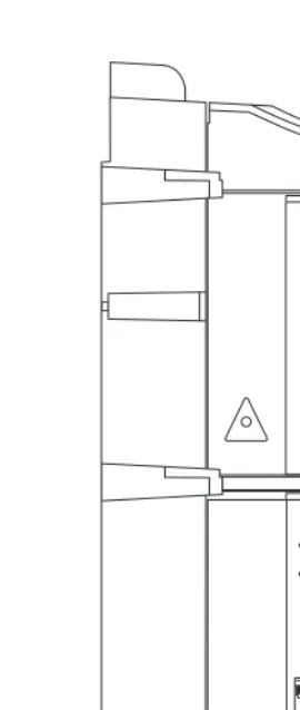
Install Sneak Fuse Panels
Sneak current protection is required between the incoming RJ21X or RJ2GX network interface and the system for both trunk and off-premises circuit packs. The model 507B sneak current fuse panel, or equivalent, is recommended for sneak current protection. See Figure 1-22.
Figure 1-22. Model 507B Sneak Fuse Panel Figure Notes
1. Sneak current protector (PEC 63210)
2. 25-pair male connector (In)
3. 25-pair female connector (Out)
4. 220029 fuses (inside panel). Use a small screwdriver to pry top cover off
Sneak Current Protector
507B
Installing and Cabling the Cabinets
1-40 Install Equipment Room Hardware
1
Approximately 8 inches (20 cm) of horizontal wall space is required for each column of sneak fuse panels. Connector cables connect the network interface to the sneak fuse panel. Also, use 157B connecting blocks equipped with SCP-110 protectors for sneak current protection.
NOTE:
Sneak current protectors with a rating of 350 mA at 600 Volts must be UL listed for United States installations and CSA certified for Canadian
installations. The panel contains two 25-pair connectors, fuse removal tool, and fifty 220029 Sneak Fuses (and 2 spares). Use the SCP-110 protectors with 110-type hardware and on the 507B Sneak Fuse Panel. The SCP-110 Protectors can be ordered separately and installed on the 157B connecting block. Fifty protectors are required per block.
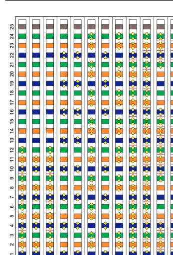
Table 1-4 is a pinout of the cable wiring and associated fuse numbers.
Table 1-4. Sneak Fuse Connector Pinout
Connector Pin Numbers
Pair/Fuse Number
26/1 1
27/2 2
28/3 3
29/4 4
30/5 5
31/6 6
32/7 7
33/8 8
34/9 9
35/10 10
36/11 11
37/12 12
38/13 13
39/14 14
40/15 15
41/16 16
42/17 17
43/18 18
44/19 19
45/20 20
46/21 2