Research on Streamlining Seismic Safety Evaluation of Underground Reinforced
Concrete Duct-Type Structures in Nuclear Power Stations
-Part-4. Analytical Simulation by Sophisticated RC Micro-model and Simple Soil Model-
Toyofinni Matsuo 1), Keizo Ohtomo 1), Jun Matsui 1) and Akihlr' o Okaichi 2)
1) Abiko Research Laboratory, Central Research Institute of Electric Power Industry, China-ken, Japan 2) Kansai Electric Power Company Ltd., Ohsaka-shi, Japan
ABSTRACT
The present p ~ deals with numerical analysis correlation with plastic deformation of scaled RC structures under dynamic soil- structure interaction. An elaborated nonlinear FEM analysis that incorporates with RC constitutive laws and hysteretic dependent soil stress-swain relation is concerned for this purpose. The accuracy of the numerical analysis result is discussed on ground response, structure deformation and soil-structure interaction. Relatively good correlation is observed in ground response and structure deformation as a result of appropriate soil nonlinear modeling. Fair estimation is also identified for soil structure interaction. Throughout the correlation work, the accuracy of the numerical analysis is found to be acceptable for engineering practice purposes.
INTRODUCTION
Earthquake resistance of underground RC structures has been one of the major research topics among earthquake engineering circles in Japan. On the contrary to so-called above ground structures, underground structures suffer from not only inertia force but also soil-structure interaction effect during an earthquake. In other words, their seismic performance is strongly affected by ground deformation. This yields somewhat complicated manner for estimating seismic force on these structures. Besides the collapse of several subways stations prompted us to study in deep and develop earthquake resistant design of underground RC structures.
Nonlinear FEM analysis is believed to be a powerful tool for assessing seismic performance and possible damage development especially during an extremely strong ground shaking. Two types of nonlinear FEM analyses are currently used in academic and
engineering practice communities. The one is rather conventional version in which moment-curvature relation is used to represent RC member deformation. The other is more sophisticated one in which straightforward RC constitutive models for concrete and reinforcement are employed. To corroborate such a tool, numerical correlations have been conducted with regards to experimental data and case histories from past earthquake damages. Shawky [1] demonstrated the accuracy of the computer program WCOMD that incorporates with soil nonlinear model for plastic deformation of scaled RC box structures under static soil-structure interaction testing. AN [2] also examined the failure mechanism of a subway station occurred during the 1995 Great Kobe Earthquake using the similar progranl The analysis well explained that the shear failure of center column triggered the structure collapse during the earthquake. However, more efforts to validate such analysis tools are needed, particularly in damage development evaluation, i.e. reinforcement yielding, concrete crack opening and the degree of plastic deformation under cyclic reversed soil-structure interaction.
As is presented in previous studies [3,4], one of the authors identified some unique astxxzts of plastic deformation of the model RC structures based on larger size shake table test. Then the p ~ object of the present patx~ is to validate nonlinear FEM analysis that employs RC constitutive models. Numerical analysis is correlated with nonlinear ground response, plastic deformation of the model RC structure and dynamic soil-structure interaction. To examine and discuss the accuracy of the RC constitutive models, emphasis is placed on yielding process and concrete crack development on the model RC slmcmres.
ANALYSES
Shake Table Test
Two cases of test were performed in a laminar shear box using a large shaking table. The awangement of the RC structure models in the laminar box is depicted in Fig. 1. One was the Fixed case, in which a two-box type RC model was fixed to the base plate of the shaking table. The other was the Unfixed case, in which the identical RC model was embedded, in the central portion of the laminar box. As far as the details of experimental procedure and results are concemed, they are presented in the related p ~ [4].
SMiRT 16, Washington DC, August 2001 Paper # 1298
ll.6m ll.6m
ill ~ ... i iiiiiiiiiii i~i i~iiii~ i~iil i~i iii~iiiii iiii/~iiiii~/~iiiii~/~iii~i~iii~/~ii::~:~i~::::~i~iii~::::~:::#~:/:::::i~::~iii~//~ii~iiii::iii~iii~i~i~iiiiiii::i::iiiiiiii
il iiiiiiiiiiiiiiiiiiiiiiiiiiiiiiiiiiiiiiii!iiiiiiiiiiii~iiii~i!i!ii~i~iiiii~ii~iiiiiiiiiiiiiiiiiiiiiiiiiiii~i~i~e~!~sii!s~h~i~i5~iiiiii !~iiiii~iii~iiiiiiiiiiiiiiiii!iii~iiiiiiiiiiiii!iiii!i¢i~/!L~iii~i~ii~i~iiii~i~iiiiiiiii!iiiiiiiiiiiiiiiii!iiiiiii!i!i~iiiiii!i~iii~i~ii~iiii~iiiiiiiiii~iiiiiii
(a) Fixed case (b) Unfixed case
Fig. 1 Arrangement of RC boxes in the Laminar shear box
Nonlinear Models for RC and Soil
In the present paper, we applied Method B defined in the related study [3]. The basic concept of the analytical model is illustrated in Fig. 2. The smeared crack model [5] developed by Okamura and Maekawa (WCOMD-SJ ver.7.1) considering RC material nonlinearity was used for structure and a total stress and strain hysteresis-d~dent model (modified version of Ohsaki's model) was adopted for soil nonlinearity.
The smeared crack model is used for representing cracked concrete with the fixed multidirecfional cracks and all the stress-strain relationships are described as spatial average stress and average strain of concrete defined in finite elements. The RC model is constructed by combining the constitutive law for concrete and reinforcing bar. The constitutive law adopted for the cracked concrete consists of tension stiffening, the compression and shear transfer models.
A path-delx~adent constitutive model for soil is indispensable for dealing with kinematic interaction of RC-soil entire system under strong seismic loads. Ohsaki's model is defined in Eq. (1) for envelope to express the nonlinear relation of the shear-stress-strain for soil as well as internal loop with Masing's rule.
7 ' = ~ l + a ~ a = ~ × O . O l - l . O
G o S u S u (1)
Where z, y are shear strain and stress, respectively. S u is ~ u m shear strength of soil (defined as shear strain at 7::1%), G o is initial shear modulus of soil, b is soil type factor (1.6 for sandy soil, 1.4 for clay soil)
_
concrete
reb
c r a c k
(a) Smeared crack model
~' s t e e l
Z"
¢7. Pc
> ~'/o 7
(b) RC material cy-~ relations (c) nonlinear soil model
Fig.2 Basic Idea of the Method B (Non-linear RC Material Model)
Numerical Models and Properties
Concrete and rebar properties that characterize the RC constitutive law are listed in Table 1. Soil properties to identify Eq. (1) are also tabulated in Table 2. Indeed, these properties were determined by laboratory soil tests to ensure appropriate stress-strain relation in relatively large (approximately 1%) strain level in numerical analysis.
I m l l l l l l l l l i l l l n l l l l
I l l l l l l i l l l l l l l l l l l l
I l l l l l l l l l l l l l l l l l l l l l l l l l l l l l l l l l l l l l l l l l l l l l l l l l l l l l l l l l l l l l l l l l l l l l l l l l l l l l l l l l l l l l l l l l l l l l l l l l l l l l l l l l l l l l l l l l l l l l l l l l l l l l l l l l l l l l l l l l l l I l l l l l l l l l l l l l l l l l l l
l l l l l l l l l l l l l l l l l l l l
i!!mm
ary • ptebcftuuu . ~ side boundary bottom boundary " prescribed _ ~ . side boundary
input acceleration ~ ~ initial stress analysis-,vertical rollers ~ initial stress analysis~vertical rollers
dynamic analysis-*horizontal rollers input acceleration dynamic analysis-,horizontal rollers
(a) Fixed case (b) Unfixed case
Fig. 3 Arrangement of FEM Mesh
Table 1 Properties for RC
Concrete
Rebar
(a) Fixed case (b) Unfixed case
33.8 2.40 23.5 265.1 185 Compression strength Tensile strength
ti0V a)
Young's modulus E~ (GPa) Yield strength(Mpa)
Young's modulus Es (GPa) Concrete Rebar Compression strength fc (MPa) Tensile strengthft(MPa)
Young's modulus E~ (GPa) Yield strengthfy(MPa
Young's modulusE s (GPa)
35.2
2.81
23.5
265.1
185
(a) Fixed case Layer
(m)
0.00--1.00 -1.00--2.00 -2.00 - -3.00 -3.00--4.00 -4.00--4.75
Table 2 Properties for Soil
Go Vs Su b
(MPa) (m/s) (kPa)
1691 104.4 785 2.21
3118 141.8 1416 1.63
4201 164.6 2065 1.41
5097 181.3 2698 1.28
5781 193.1 3236 1.20
(b) Unfixed case Layer
(m)
0.00--1.00 -1.00--2.00 -2.00 - -3.00 -3.00 - -3.75 -3.75 --4.75
o0
(MPa)
1629 3087 4183 4994 5706Vs Su b
(m/s) (kPa)
102.5 765 2.25
141.5 1400 1.64 1 64.2 2054 1.41 179.4 2620 1.29 191.8 3175 1.21
RESULTS AND DISCUSSIONS
So.Structure System
Numerical analysis correlation is discussed for both Fixed and Unfixed cases under 1127 and 1041Gal in peak ac~leratiort, respectively.
Fig. 5 compares experimental and analytical results for the relative displacement of the model RC structure in time history. Where the relative displacement is defined as the displacement between top and bottom slabs. Hereafter, this definition is used throughout the present p ~ unless corffusion occurs. In Fixed case, the analytical result provides considerably good correlation for phase and peak response. In addition, residual relative displacement is satisfactorily estimatecL In Unfixed case, however, the analytical result significantly underestimates the experimental result, particularly in negative peak estimation. This seems to be due to the fact that bond condition for soil-slmcture interface is applied for the FEM model, although clear slippage between soil and the top slap surface was observed in the Unfixed case. Though more elaborate modeling for Unfixed case is needed, the analytical results are considered to be fair to good, which suggests that the FEM analysis model discussed in the present study appears to be still a powerful tool for practical design ptatx)ses.
4
0 ¢9 m
~5-4
l : xperiment ]
V---]
0 1 2 3 4 5
T i m e (second)
(a) Fixed 1127Gal case
[ [---- xporimont 1
~-4
-8
0 1 2 3 4 5
Time(second)
(b) Unfixed 1041Gal case
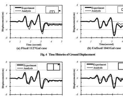
Fig. 4 Time Histories of Ground Displacement
[¸'--Experiment¸
Experiment
"~ 4 - - A n a l y s i s ~ - - - Analysis ~ 4 -
-4 N -4
-8 -8
0 1 2 3 4 5 0 1 2 3 4 5
Time(second) Time(second)
(a) Fixed l127Gal case (b) Unfixed 1041Gal case
Fig. 5 Time histories of the Relative Displacement
Experiment 6 Analysis
=:4
g
L~ 2
~o
"'~ -2
-4
_ x , ~ , ,
t /
/ /
/
2
0 •
-2
/~~
•4
/
/
, ° i °
-6 -4 -2 0 2 4 6 -6 -4 -2 0 2 4 6 '
s h e a r s t r a i n i n s o i l ( % )
s h e a r s t r a i n i n s o i l ( % )
6 o
"~ 4 -
E 2 c o .N
0
'~ -2 E
r~ -6
(a) Fixed case
Experiment Analysis
/
¢
U,I . . . .
/
64 E
2
0
-2 E ,~ -4
r~ -6
/
../
/
, , | | | | , ° ,
-6 -4 -2 0 2 4 6 -6 -4 -2 0 2 4 6
s h e a r s t r a i n i n s o i l ( % ) s h e a r s t r a i n i n s o i l ( % )
(b) Unf~ed case
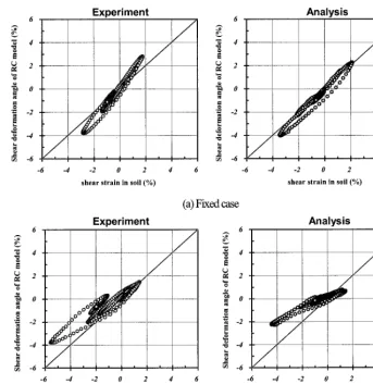
Fig. 6 Shear Deformation Angle of RC Model with respect to that of Soil
Nonlinear Ground Response
Figure 7 shows experimental and analytical results of the horizontal ground surface acceleration for Fixed and Unfixed cases. Exlremely good correlation involving shorter period components is obtained in acceleration time histories.
8 and 9 illustrate the comparisons of experimental and analytical results for distribution of maximum horizontal acceleration and horizontal d i s p l ~ e n t . In acceleration response distribution, amplitude reduction with respect to elevation arising from soil nonlinearity can be well explained by the numerical analysis. On the other hand in displacement distribution response, the numerical analysis gives smaller d i s p l ~ e n t response in shallower part of the laminar shear box. This seems to be as a result of inaccurate estimation of soil nonlinearity under low confining pressure.
1200 1200
.h
1
" ' E x p e r i m e n tl
I
~oo
800 --- Analysis
~,~ 400 ~ll ~ 400
"Y= 0
400
t 24,j
400
-800 = : ~ -800
I ' l ' I ' ', '
-1200 -1200
0 1 2 3 4 5
Time (sec) (a) Fixed l 1 2 7 G a l case
~ E x p e r i m e n t Analysis
j
•
L
j
0 1 2 3 4 5
Time (see) (b) Unfixed l 1 2 7 G a l ease
I ~mOmmExperimen t ---tP-- Analysis 5
4 " 2 )
~ 2 1
0 . . . . ' ' ' '
0 500 1000 1500
acceleration (Gal)
(a) F i x e d 1 1 2 7 G a l c a s e
4
~ 2
0 . . . L , , ,
0 500 1000 1500
acceleration (Gal)
(b) U n f i x e d 1 0 4 1 G a l c a s e
Analysis ~ A n a l y s i s ~ Analysis
5 5
• J ~ '
4"
I~P
4"
/ /P
/ /
-
~
~ 2 ~ 2• 1 1
0 " " ' 0 . . . .
20 30 0 10 20 30
displacement (cm)
(b) U n f i x e d 1 0 4 1 G a l c a s e
0 10
displacement (cm)
(a) F i x e d l 1 2 7 G a l c a s e
Fig. 8 Distribution of Maximum Horizontal Acceleration Fig. 9 Distribution of Maximum Horizontal Displacement
Damage Process
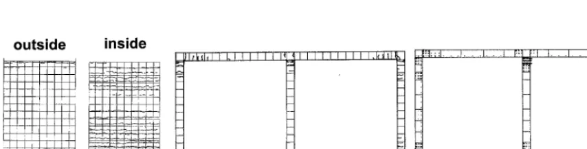
Comparisons of observed and analyzed concrete clack patterns are sketched in Fig. 10. In the experiment, extensive cracks were localized at the upper and lower comers of RC structure models. As is illustrated in Fig. 10(a), concrete cracks are developed significantly on the inside face of the sidewalls. This is possibly due to the effect of higher degree of compression dynamic earth preast~e on the sidewalls during the excitation. These crack behaviors can be well reproduced by the analysis.
outside
t
inside
West wall
]l~Itd,l I I.I I I I I I I~_~ I I I I I I I I I I,I~NII ~_ ~ ~. _~
_ _ ,, _
= ~
z-
_ ~ i • =
i I I I I I I I1 I I I I I I I I I I I I I I I I I I I '1 I I I
(a) Experiment (b) Analysis
Y
Fig. 10 Concrete Crack Patterns (Fixed case)
®
®
m ; u n ~ k t i n g ( ~ ) . ~~i ii
ii
®
®
®l
@
r~yiekUng
Deformation direction~
®
®
) Experiment
_,
,,~y~a~
®(i)
(1o) Analysis
+--Deformation direction
®
@
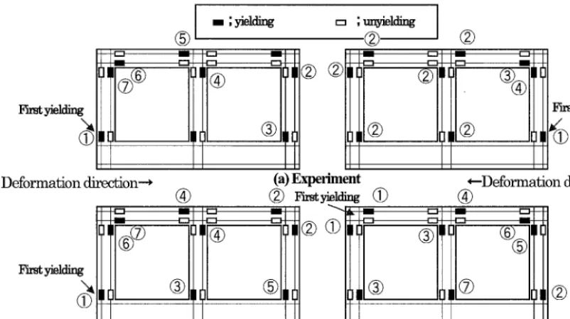
Fig. 11 Locations of Yielding Positions (Fixed case)
Soil-Structure Interaction
Figure 12 compares experimental and analytical results on dynamic earth pressure on the sidewall. In the shake table test [4], the dynamic earth pressure acted in compression manner in spite of cyclic reversed deformation of the model RC structure. In addition, this performance was arising fi'om volume change of soils. Although soil nonlinearity model employed in the numerical analysis incorporates with only linear elastic volume change relation, time histories of the estimated dynamic earth pressure appears to be fair for expressing unique characteristics of the measured dynamic earth pressure.
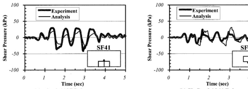
Figure 13 discusses dynamic shear stress on the top slab surface. As is presented in the previous study [4], this force component is responsible for the degree of plastic deformation of the model RC structure. The numerical analysis provides good correlation with measured dynamic shear stress for both Fixed and Unfixed cases. This supports the fact that the relative displacement of the model RC structure is well estimated as shown in Fig. 5.
lOO
." ~ E x p e r i m e n t 50
l , t r ~ 0
-50 --
-100 .
EP13
[ I 3
a I I I m I m I a
1 2 3
Time (see) (a) Fixed l127Gal ease
4 5
1 ° ° t [ ~ E x p e r i m e n t
~ •
~., 50
r~
0
¢o I,i
-50
-100
0 1 2 3 4 5
Time (sec) (b) Unfixed 1041Gal case
100 t " ' E x p e r i m e n t
~ [ ---Analysis l
5 0
0
r~ - 5 0 r ~
- 1 0 0
0 1 2 3 4 5
Time (sec)
(a) F i x e d l 1 2 7 G a l case
1 0 0 •
5 0 - 0 .' - 5 0 -
- 1 0 0 • 0
Fig. 13 Shear Stress
• ~ E x p e r i m e n t
- - - Analysis
• S F 4 2
1 2 3
Time (see) (b) U n f i x e d 1 0 4 1 G a l case
4 5
CONCLUSIONS
Numerical analysis correlation with the shake table test on plastic deformation performance of the model RC structure is discussed. The nonlinear FEM analysis code that incorporates with RC constitutive laws and hysteretic d ~ d e n t soil stress- strain relationship is applied for this ptupose. The accuracy of the numerical analysis is examined in regard to ground restx~nse, structure deformation and dynamic soil-structure interaction. Thanks to appropriate model parameters incorporetd in the soil nonlinear model, the numerical analysis is found to have an acceptable estimation for nonlinear ground response. With this advantage, the degree of plastic deformation and damage process of the model RC structures is successfully estimated, particularly in Fixed case. This is believed to be due to the fact that the model RC structure performance is totally govemed by surrounding soil deformation dtuing the shake table test. In addition, dynamic soil-structure interaction effects such as dynamic earth pressure on the sidewall and shear stress on the top slab are numerically correlated with measured results. Although the soil nonlinear mode excludes soil volume change, i.e. dilatancy effect, the numerical analysis gives fair estimation on dynamic earth preas~e. On the contrary, estimated shear stress is considered to be well correlated with experimental result. This also supports that degree of the s~ucmre deformation is satisfactorily evaluated. Unbond interface condition, which is essential to express possible slippage and/or separation, is needed to discuss in deep the accuracy of the nonlinear FEM model. The effort for this issue is ctarently under way.
A C K N O W I ~ E D G E M E N T
The foregoing study is a part of the joint research entitled "Development Study on Verification Method of Seismic Performance of Underground Reinforced Concrete Structures in Nuclear Power Stations (part-2)" which is supported by Electric Power Industry in Japan and extends fi'om 1997 through 2001. The managing company is Kansai Electric Power Co. Ltck The authors are very grateful to the above organizations. They also appreciate valuable advices given by the committee o r g a n i z e d in JSCE and chaired by Pro£ Hajime Okamura, President of Kochi Institute of Technology.
R E F E R E N C E S
1) Shawky, A. and Maekawa, K, "Collapse mechanism of underground RC structures during Hansin Great Earthquake", Cario first Intematinal Conference on Concrete Structures, 1996.
2) Xuehui AN and Maekawa, K., "Failure analysis of underground RC frame subjected to seismic actions", J. Materials, Conc. Stmct., Pavements, JSCE, No.571/V-36, 1997, pp.251-267.
3) Aoyagi, K., Kanazu, T., Endoh, T. and Okaichi, A., "Part-1. Scope, Objectives and Major Results of the Research" To be published on Transactions of the 16th International Conference on Structural Mechanics in Reactor Technology, Vol. K, paper number 1295, 2001.
4) Ohtomo, K., Suehiro, T., Kawai, T. and Kanaya, K., "Part-2. Experimental Aspects of Laminar Shear Sand Box Excitation Tests with Embedded RC Models" To be published on Transactions of the 16th International Conference on Structural Mechanics in Reactor Technology, Vol. K, paper number 1295,2001.
![Fig. 2. The smeared crack model [5] developed by Okamura and Maekawa (WCOMD-SJ ver.7.1) considering RC material In the present paper, we applied Method B defined in the related study [3]](https://thumb-us.123doks.com/thumbv2/123dok_us/1677241.1211317/2.596.72.468.449.559/developed-okamura-maekawa-considering-material-present-applied-method.webp)